Dry Rolling/Sliding Wear of Bainitic Rail Steels under Different Contact Stresses and Slip Ratios


Abstract
1. Introduction
2. Experiments
2.1. Experimental Materials and Parameters
2.2. Characterizations
3. Results
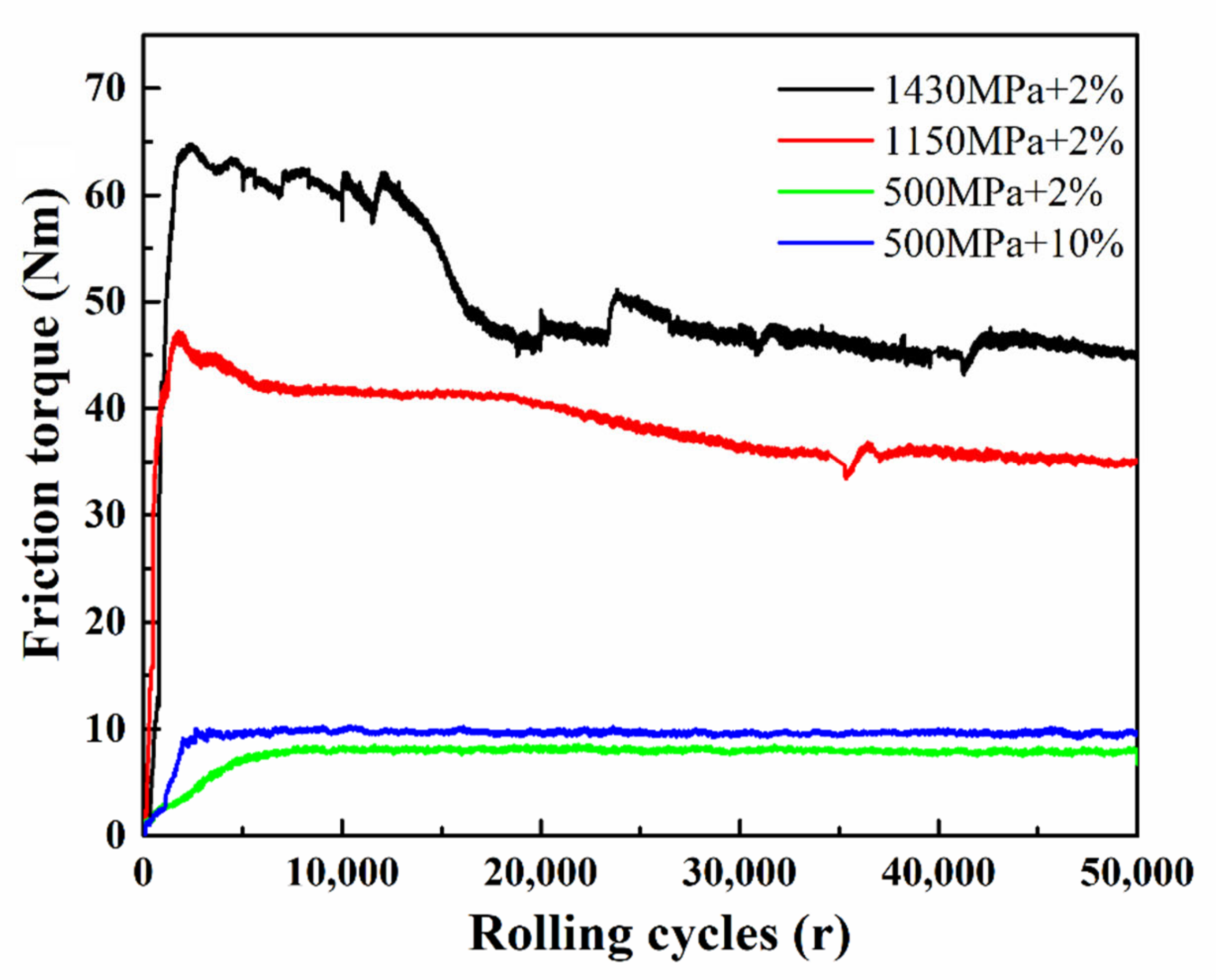
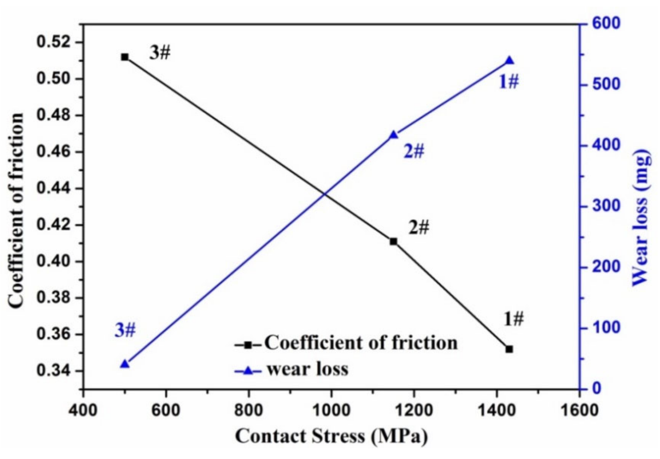
3.1. Wear Behaviors
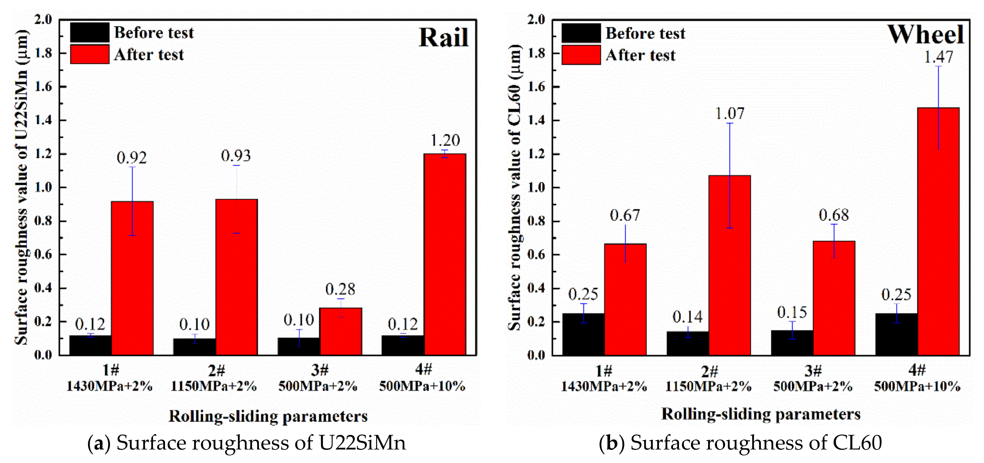
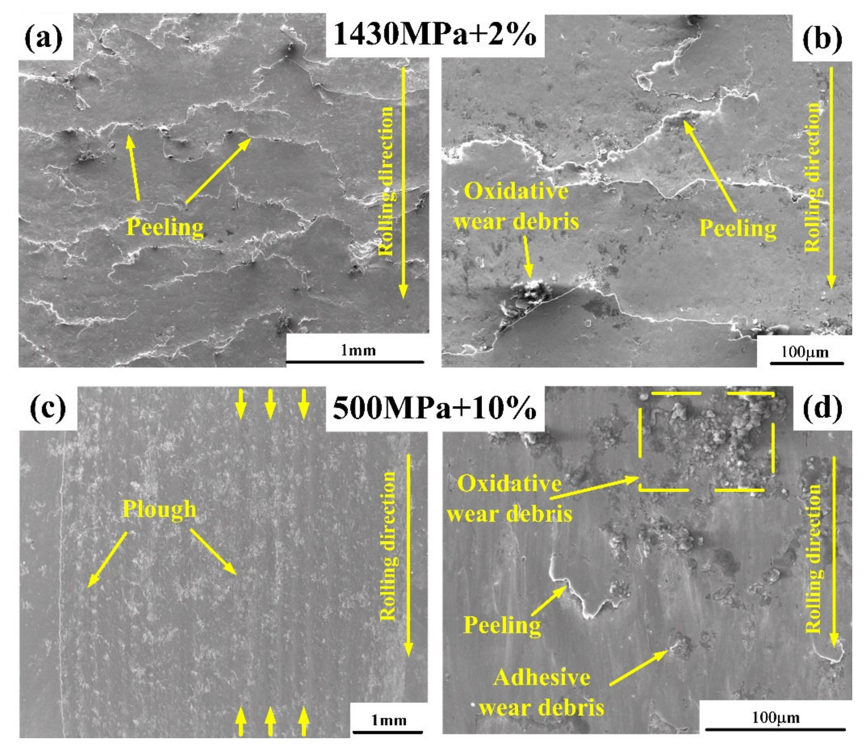
3.2. Investigations on Worn Surface
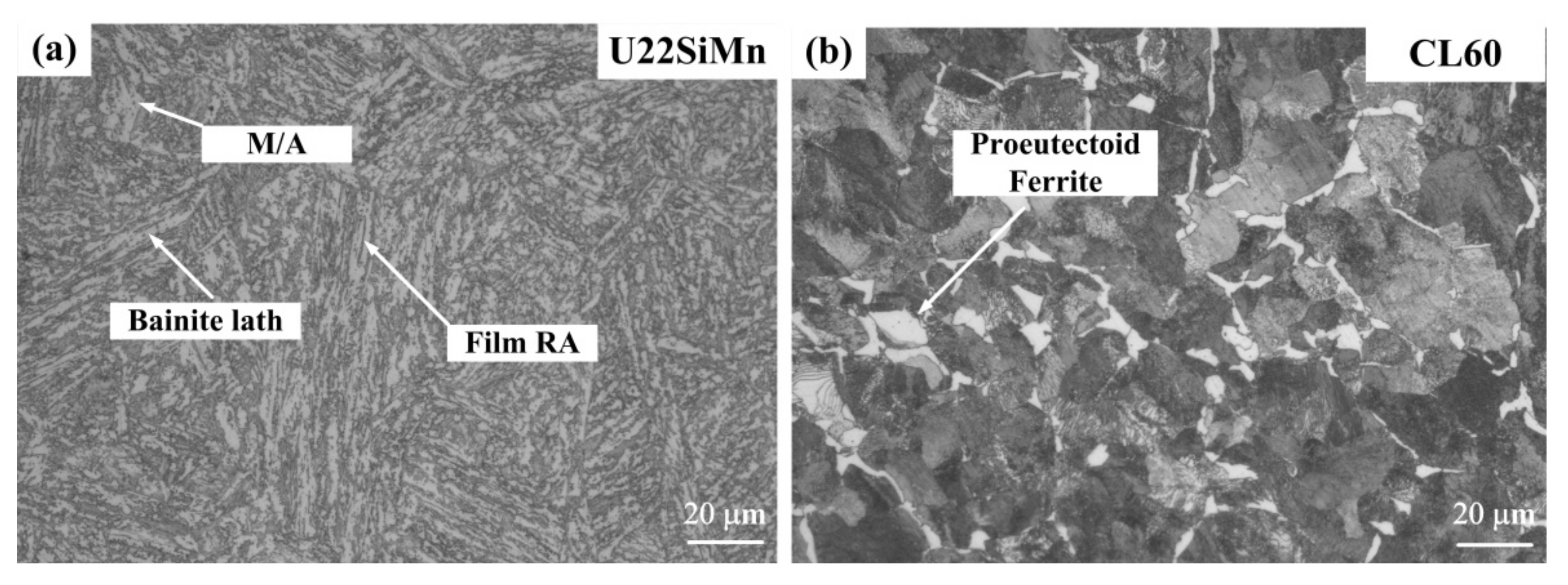
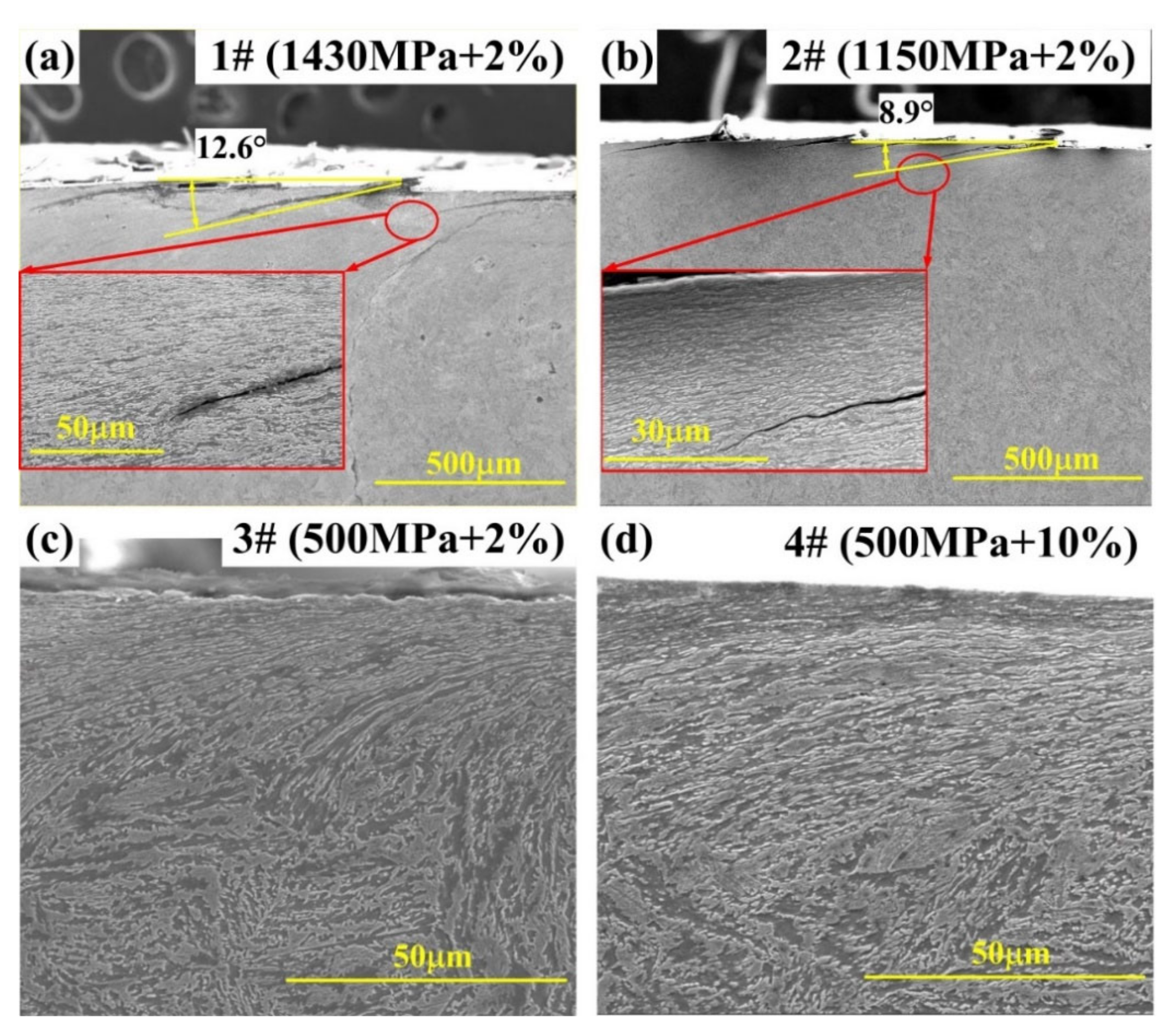
3.3. The Analysis of Cross-Sectional Microstructure
3.4. The Transformation of Retained Austenite during Wear Tests
4. Discussion
4.1. Effect of the Contact Stress on the Wear Resistance and RCF Resistance of Bainitic Steel
4.2. Effect of the Slip Ratio on the Wear Resistance and RCF Resistance of Bainitic Steel
4.3. Influence of the Contact Stress and Slip Ratio on the Transformation of RA
5. Conclusions
- The wear loss increases with the rise of the contact stress and slip ratio, but the slip ratio plays a more crucial role on aggravating wear loss than the contact stress.
- The rolling contact fatigue wear mechanism plays a significant role under the low slip ratio condition, but the dominant wear mechanism transfers to the abrasive wear at the high slip ratio. The bainitic steel is not suitable for the small-radius curves with the high slip ratio due to its worse wear resistance under the abrasive wear mode.
- The enhancement of contact stress has much more tendency to develop plastic flows and contribute to the propagation of cracks in the bainitic steels than the increase in slip ratio.
- The friction coefficient of bainitic steels has an inverse proportion with the contact stress, but positive proportion with the slip ratio.
- The volume fraction of RA decreases with the increase in contact stress and slip ratio. The increase in slip ratio has a more significant effect on the reduction of RA than the enlargement of contact stress due to the fact that the RA phase would probably be removed before the MT occurred under the abrasive wear mechanism.
Author Contributions
Funding
Acknowledgments
Conflicts of Interest
References
- Ueda, M.; Matsuda, K. Effects of carbon content and hardness on rolling contact fatigue resistance in heavily loaded pearlitic rail steels. Wear 2020, 444–445, 203120. [Google Scholar] [CrossRef]
- Kumar, A.; Dutta, A.; Makineni, S.; Herbig, M.; Petrov, R.; Sietsma, J. In-situ observation of strain partitioning and damage development in continuously cooled carbide-free bainitic steels using micro digital image correlation. Mater. Sci. Eng. A 2019, 757, 107–116. [Google Scholar] [CrossRef]
- Sourmail, T.; Caballero, F.; Garcia-Mateo, C.; Smanio, V.; Ziegler, C.; Kuntz, M.; Elvira, R.; Leiro, A.; Vuorinen, E.; Teeri, T. Evaluation of potential of high Si high C steel nanostructured bainite for wear and fatigue applications. Mater. Sci. Technol. 2013, 29, 1166–1173. [Google Scholar] [CrossRef]
- Kumar, A.; Makineni, S.; Dutta, A.; Goulas, C.; Steenbergen, M.; Petrov, R.; Sietsma, J. Design of high-strength and damage-resistant carbide-free fine bainitic steels for railway crossing applications. Mater. Sci. Eng. A 2019, 759, 210–223. [Google Scholar] [CrossRef]
- Leiro, A.; Kankanala, A.; Vuorinen, E.; Prakash, B. Tribological behaviour of carbide-free bainitic steel under dry rolling/sliding conditions. Wear 2011, 273, 2–8. [Google Scholar] [CrossRef]
- Hu, F.; Wu, K.M.; Hodgson, P.D. Effect of retained austenite on wear resistance of nanostructured dual phase steels. Mater. Sci. Technol. 2016, 32, 40–48. [Google Scholar] [CrossRef]
- Masoumi, M.; Ariza, E.A.; Sinatora, A.; Goldenstein, H. Role of crystallographic orientation and grain boundaries in fatigue crack propagation in used pearlitic rail steel. Mater. Sci. Eng. A 2018, 722, 147–155. [Google Scholar] [CrossRef]
- Zhou, Y.; Wang, S.; Wang, T.; Xu, Y.; Li, Z. Field and laboratory investigation of the relationship between rail head check and wear in a heavy-haul railway. Wear 2014, 315, 68–77. [Google Scholar] [CrossRef]
- Ding, H.; Fu, Z.; Wang, W.; Guo, J.; Wang, W.; Zhu, M. Investigation on the effect of rotational speed on rolling wear and damage behaviors of wheel/rail materials. Wear 2015, 330–331, 563–570. [Google Scholar] [CrossRef]
- Huang, Y.; Shi, L.; Zhao, X.; Cai, Z.; Wang, W.; Wang, W. On the formation and damage mechanism of rolling contact fatigue surface cracks of wheel/rail under the dry condition. Wear 2018, 40–401, 62–73. [Google Scholar] [CrossRef]
- Guo, L.; Zhu, W.; Shi, L.; Liu, Q.; Cai, Z.; Wang, W. Study on wear transition mechanism and wear map of CL60 wheel material under dry and wet conditions. Wear 2019, 426–427, 1771–1780. [Google Scholar] [CrossRef]
- Johnson, S.M.; Marín, J.F.S.; Toro, A. Dry and lubricated wear of rail steel under rolling contact fatigue—Wear mechanisms and crack growth. Wear 2017, 380–381, 240–250. [Google Scholar] [CrossRef]
- Dylewski, B.; Salima, B.; Marion, R. Multiscale characterization of head check initiation on rails under rolling contact fatigue: Mechanical and microstructure analysis. Wear 2016, 366–367, 383–391. [Google Scholar]
- Messaadi, M.; Oomen, M.; Kumar, A. Friction modifiers effects on tribological behaviour of bainitic rail steels. Tribol. Int. 2019, 140, 105857. [Google Scholar] [CrossRef]
- Stock, R.; Pippan, R. RCF and wear in theory and practice—The influence of rail grade on wear and RCF. Wear 2011, 271, 125–133. [Google Scholar] [CrossRef]
- Lee, K.M.; Polycarpou, A.A. Wear of conventional pearlitic and improved bainitic rail steels. Wear 2005, 259, 391–399. [Google Scholar] [CrossRef]
- Hasan, S.M.; Chakrabarti, D.; Singh, S.B. Dry rolling/sliding wear behaviour of pearlitic rail and newly developed carbide-free bainitic rail steels. Wear 2018, 408, 151–159. [Google Scholar] [CrossRef]
- Liu, J.; Li, Y.; Zhou, Q.; Zhang, Y.; Hu, Y.; Shi, L.; Wang, W.; Liu, F.; Zhou, S.; Tian, C. New insight into the dry rolling-sliding wear mechanism of carbide-free bainitic and pearlitic steel. Wear 2019, 432–433, 202943. [Google Scholar] [CrossRef]
- Chen, Y.; Ren, R.; Pan, J.; Pan, R.; Zhao, X. Microstructure evolution of rail steels under different dry sliding conditions: A comparison between pearlitic and bainitic microstructures. Wear 2019, 438–439, 203011. [Google Scholar] [CrossRef]
- Yokoyama, H.; Mitao, S.; Yamamoto, S.; Fujikake, M. Effect of the angle of attack on flaking behavior in pearlitic and bainitic steel rails. Wear 2002, 253, 60–66. [Google Scholar] [CrossRef]
- Chang, L. The rolling/sliding wear performance of high silicon carbide-free bainitic steels. Wear 2005, 258, 730–743. [Google Scholar] [CrossRef]
- Devanathan, R.; Clayton, P. Rolling-sliding wear behavior of three bainitic steels. Wear 1991, 151, 255–267. [Google Scholar] [CrossRef]
- Robles-Hernández, F.C.; Demas, N.G.; Davis, D.D.; Polycarpou, A.A.; Maal, L. Mechanical properties and wear performance of premium rail steels. Wear 2007, 263, 766–772. [Google Scholar] [CrossRef]
- Garnham, J.; Beynon, J. Dry rolling-sliding wear of bainitic and pearlitic steels. Wear 1992, 157, 81–109. [Google Scholar] [CrossRef]
- Leiro, A.; Vuorinen, E.; Sundin, K.; Prakash, B.; Sourmail, T.; Smanio, V.; Caballero, F.; Garcia-Mateo, C.; Elvira, R. Wear of nano-structured carbide-free bainitic steels under dry rolling–sliding conditions. Wear 2013, 298, 42–47. [Google Scholar] [CrossRef]
- Shipway, P.; Wood, S.; Dent, A. The hardness and sliding wear behaviour of a bainitic steel. Wear 1997, 203, 196–205. [Google Scholar] [CrossRef]
- Moghaddam, P.V.; Hardell, J.; Vuorinen, E.; Prakash, B. The role of retained austenite in dry rolling/sliding wear of nanostructured carbide-free bainitic steels. Wear 2019, 428–429, 193–204. [Google Scholar] [CrossRef]
- Liu, B.; Li, W.; Lu, X.; Jia, X.; Jin, X. The effect of retained austenite stability on impact-abrasion wear resistance in carbide-free bainitic steels. Wear 2019, 428–429, 127–136. [Google Scholar] [CrossRef]
- Xu, X.; Xu, W.; Ederveen, F.H.; Van Der Zwaag, S. Design of low hardness abrasion resistant steels. Wear 2013, 301, 89–93. [Google Scholar] [CrossRef]
- Liu, B.G.; Lu, X.W.; Li, W.; Jin, X.J. Enhanced wear resistance of nano-twinned austenite in higher Si nanostructured bainitic steel. Wear 2018, 398–399, 22–28. [Google Scholar] [CrossRef]
- Liu, J.; Li, Y.; Jin, J.; Zhang, Y.; Liu, F.; Su, R.; Narayanaswamy, B.; Zhou, Q. Effect of processing techniques on microstructure and mechanical properties of carbide-free bainitic rail steels. Mater. Today Commun. 2020, 25, 101531. [Google Scholar] [CrossRef]
- Lewis, R.; Magel, E.; Wang, W.-J.; Olofsson, U.; Lewis, S.; Slatter, T.; Beagles, A. Towards a standard approach for the wear testing of wheel and rail materials. Proc. Inst. Mech. Eng. Part F J. Rail Rapid Transit 2017, 231, 760–774. [Google Scholar] [CrossRef]
- Budynas, R.; Nisbett, K. Shigley’s Mechanical Engineering Design, 8th ed.; McGraw-Hill: New York, NY, USA, 2009. [Google Scholar]
- Xu, H.F.; Zhao, J.; Cao, W.Q.; Shi, J.; Wang, C.Y.; Li, J.; Dong, H. Tempering effects on the stability of retained austenite and mechanical properties in a medium manganese steel. ISIJ Int. 2012, 52, 868–873. [Google Scholar] [CrossRef]
- Stachowiak, G.W.; Batchelor, A.W. Engineering Tribology, 4th ed.; Butterworth-Heinemann: Oxford, UK, 2014; p. 884. [Google Scholar]
- Sedlaček, M.; Podgornik, B.; Vižintin, J. Influence of surface preparation on roughness parameters, friction and wear. Wear 2009, 266, 482–487. [Google Scholar] [CrossRef]
- Liu, J.; Jiang, W.; Chen, S.; Liu, Q. Effects of rail materials and axle loads on the wear behavior of wheel/rail steels. Adv. Mech. Eng. 2016, 8. [Google Scholar] [CrossRef]
- Chen, H.; Namura, A.; Ishida, M.; Nakahara, T. Influence of axle load on wheel/rail adhesion under wet conditions in consideration of running speed and surface roughness. Wear 2016, 366–367, 303–309. [Google Scholar] [CrossRef]
- Lewis, R.; Christoforou, P.; Wang, W.; Beagles, A.; Burstow, M.; Lewis, S. Investigation of the influence of rail hardness on the wear of rail and wheel materials under dry conditions (ICRI wear mapping project). Wear 2019, 430–431, 383–392. [Google Scholar] [CrossRef]
- Bower, A.; Johnson, K. Plastic flow and shakedown of the rail surface in repeated wheel-rail contact. Wear 1991, 328–329, 149–159. [Google Scholar] [CrossRef]
- Białobrzeska, B.; Kostencki, P. Abrasive wear characteristics of selected low-alloy boron steels as measured in both field experiments and laboratory tests. Wear 2015, 328–329, 149–159. [Google Scholar]
- Das Bakshi, S.; Leiro, A.; Prakash, B.; Bhadeshia, H. Dry rolling/sliding wear of nanostructured bainite. Wear 2014, 316, 70–78. [Google Scholar] [CrossRef]
- Vuorinen, E.; Prakash, B. Influence of retained austenite on rolling-sliding wear resistance of austempere; Verlag Wissenschaftliche Scripten: Auerbach/Vogtland, Germany, 2015. [Google Scholar]
- Lian, Q.; Deng, G.; Tieu, A.K.; Li, H.; Liu, Z.; Wang, X.; Zhu, H. Thermo-mechanical coupled finite element analysis of rolling contact fatigue and wear properties of a rail steel under different slip ratios. Tribol. Int. 2020, 141, 105943. [Google Scholar] [CrossRef]


| Component | Steel Grade | C | Si | Mn | P | S | Cr + V |
|---|---|---|---|---|---|---|---|
| Rail | U22SiMn | 0.20–0.23 | 1.30–1.35 | 2.00–2.10 | ≤0.025 | ≤0.025 | ≤0.589 |
| Wheel | CL60 | 0.58–0.60 | 0.20–0.25 | 0.72–0.74 | ≤0.030 | ≤0.030 | ≤0.14 |
| Component | Steel Grade | Rm/MPa | Rp0.2/MPa | A/% | Bulk Hardness/HBW |
|---|---|---|---|---|---|
| Rail | U22SiMn | 1283 | 1123 | 16.0 | 401 |
| Wheel | CL60 | 932 | 593 | 17.0 | 286 |
| Testing Groups | Normal Load (N) | Contact Stress (MPa) | Slip Ratio (%) | Rolling Speed of Wheel (rpm) |
|---|---|---|---|---|
| 1# | 4300 | 1430 | 2 | 500 |
| 2# | 2850 | 1150 | 2 | 500 |
| 3# | 520 | 500 | 2 | 500 |
| 4# | 520 | 500 | 10 | 500 |
| Test Group | Normal Load(N) | Friction Torque (Nm) | Disc Radius (mm) | Friction Force (N) | Coefficient of Friction |
|---|---|---|---|---|---|
| 1# | 4300 | 45.20 | 29.89 | 1512 | 0.352 |
| 2# | 2850 | 35.00 | 29.93 | 1169 | 0.411 |
| 3# | 520 | 7.96 | 29.93 | 266 | 0.512 |
| 4# | 520 | 9.56 | 29.35 | 326 | 0.627 |
| Testing Groups | Number of Cracks | Average Depth (μm) | Max Depth (μm) | Average Inclination Angle (°) |
|---|---|---|---|---|
| 1# | 18 | 85 ± 4 | 126 | 9.1 ± 1.3 |
| 2# | 17 | 38 ± 3 | 71 | 6.7 ± 1.0 |
| 3# | 3 | 8 ± 2 | 11 | 6.6 ± 1.0 |
| 4# | 4 | 11 ± 2 | 24 | 8.0 ± 1.5 |
| 1# (1430 MPa + 2%) | 2# (1150 MPa + 2%) | 3# (500 MPa + 2%) | 4# (500 MPa + 10%) | |
|---|---|---|---|---|
| VF of RA before wear | 9.33% | 9.33% | 9.33% | 9.33% |
| VF of RA after wear | 4.77% | 4.96% | 8.98% | 0.58% |
Publisher’s Note: MDPI stays neutral with regard to jurisdictional claims in published maps and institutional affiliations. |
© 2020 by the authors. Licensee MDPI, Basel, Switzerland. This article is an open access article distributed under the terms and conditions of the Creative Commons Attribution (CC BY) license (http://creativecommons.org/licenses/by/4.0/).
Share and Cite
Liu, J.; Li, Y.; Zhang, Y.; Hu, Y.; Shi, L.; Ding, H.; Wang, W.; Liu, F.; Zhou, S.; Shi, T. Dry Rolling/Sliding Wear of Bainitic Rail Steels under Different Contact Stresses and Slip Ratios. Materials 2020, 13, 4678. https://doi.org/10.3390/ma13204678
Liu J, Li Y, Zhang Y, Hu Y, Shi L, Ding H, Wang W, Liu F, Zhou S, Shi T. Dry Rolling/Sliding Wear of Bainitic Rail Steels under Different Contact Stresses and Slip Ratios. Materials. 2020; 13(20):4678. https://doi.org/10.3390/ma13204678
Chicago/Turabian StyleLiu, Jiapeng, Yingqi Li, Yinhua Zhang, Yue Hu, Lubing Shi, Haohao Ding, Wenjian Wang, Fengshou Liu, Shaobo Zhou, and Tong Shi. 2020. "Dry Rolling/Sliding Wear of Bainitic Rail Steels under Different Contact Stresses and Slip Ratios" Materials 13, no. 20: 4678. https://doi.org/10.3390/ma13204678
APA StyleLiu, J., Li, Y., Zhang, Y., Hu, Y., Shi, L., Ding, H., Wang, W., Liu, F., Zhou, S., & Shi, T. (2020). Dry Rolling/Sliding Wear of Bainitic Rail Steels under Different Contact Stresses and Slip Ratios. Materials, 13(20), 4678. https://doi.org/10.3390/ma13204678