Article

On the Microstructure and Properties of Nb-18Si-6Mo-5Al-5Cr-2.5W-1Hf Nb-Silicide Based Alloys with Ge, Sn and Ti Additions (at.%)

1
Department of Materials Science and Engineering, Sir Robert Hadfield Building, The University of Sheffield, Mappin Street, Sheffield S1 3JD, UK
2
College of Materials and Chemical Engineering, Key Laboratory of Inorganic Nonmetallic Crystalline and Energy Conversion Materials, Three Gorges University, Yichang 443002, China
*
Author to whom correspondence should be addressed.
Materials 2020, 13(20), 4548; https://doi.org/10.3390/ma13204548
Submission received: 23 September 2020 / Revised: 5 October 2020 / Accepted: 6 October 2020 / Published: 13 October 2020

Abstract

:
We studied the microstructures and isothermal oxidation of the Nb-silicide-based alloys Nb-11.5Ti-18Si-5Mo-2W-4.9Sn-4.6Ge-4.5Cr-4.7Al-1Hf (JZ4) and Nb-21Ti-18Si-6.7Mo-1.2W-4.4Sn-4.2Ge-4Cr-3.7Al-0.8Hf (JZ5), calculated their average creep rate for the creep goal conditions of T = 1200 °C and σ = 170 MPa, and compared properties of the two alloys with those of other refractory metal (RM) complex concentrated alloys (RCCAs). Both alloys had a density less than 7.3 g/cm3 and lower than the density of multiphase bcc solid solution + M5Si3 silicide RCCAs. There was macrosegregation of Si in both alloys, which had the same phases in their as-cast microstructures, namely βNb5Si3, αNb5Si3, A15-Nb3X (X = Al, Ge, Si, Sn), TM5Sn2X (X = Al, Ge, Si), C14-Cr2Nb, but no solid solution. After heat treatment at 1500 °C for 100 h, a low volume fraction of a W-rich (Nb, W)ss solid solution was observed in both alloys together with βNb5Si3, αNb5Si3 and A15-Nb3X but not the TM5Sn2X, whereas the Laves phase was observed only in JZ4. At 800 °C, both alloys did not pest, and there was no spallation of their scales at 1200 °C. At both temperatures, both alloys followed parabolic oxidation kinetics and their weight changes were lower than those of Ti-rich Nb-silicide-based alloys. The oxidation of both alloys was superior to that of other RCCAs studied to date. For each alloy the Si macrosegregation, volume fraction of solid solution, chemical composition of solid solution and Nb5Si3, and weight changes in isothermal oxidation at 800 and 1200 °C that were calculated using the alloy design methodology NICE agreed well with the experimental results.

1. Introduction

Ultra-high temperature materials (UHTMs) are currently being developed as potential replacements of Ni-based superalloys to meet performance and environmental targets in future aero engines. Metallic UHTMs are refractory metal (RM) intermetallic composites (RMICs), RM high entropy alloys (RHEAs) and RM complex concentrated alloys (RCCAs) [1,2]. RMICs include Nb- or Mo-silicide-based alloys [3,4,5]. Nb-silicide-based alloys are attracting much attention for blade applications [1,3]. Some Nb-silicide-based alloys are also RCCAs [1].
Metallic UHTMs must meet property goals for creep, toughness and oxidation resistance [3,4,6]. The creep strength should be greater than 170 MPa at a creep rate of 2 × 10⁻⁸ s−1 at 1200 °C (for Nb-silicide-based alloys, this goal assumes density ρ = 7 g/cm3). The fracture toughness of critical components should be ≥20 MPa√m. The recession rate due to oxidation should be less than 0.25 μm/h at 1315 °C. The oxidation goal is derived from the requirement of achieving the oxidation life at 1315 °C of the second generation single crystal Ni-based superalloys at 1150 °C. The toughness goal requires metallic behaviour of the metallic UHTMs to distinguish them from engineering ceramics or ceramic UHTMs. Thus, owing to the toughness goal, the new metallic materials should have at least a small volume fraction of a ductile, metallic phase. The latter is the bcc Nb solid solution in the case of Nb-silicide-based alloys [1,4,7].
Research has ascertained the key role of specific alloying additions for meeting property goals in Nb-silicide-based alloys [3,7,8,9,10,11,12,13,14,15,16,17,18,19,20]. RM additions are indispensable for strength and creep, simple metal and metalloid element (SMME) and transition metal (TM) additions are needed for oxidation resistance and TMs and SMMEs are crucial for toughness (RM = Mo, Ta, W, SMME = Al, B, Ge, Si, Sn, TM = Cr, Hf, Ti) [1,20,21,22,23,24,25]. Processing can have a significant effect on toughness [1]. Nb-silicide-based alloys can meet the creep and toughness goals and have closed substantially the gap with the oxidation goal. It is not likely that a metallic UHTM could meet all three property goals [1,4,20,26].
Contamination of RMs and RM alloys by interstitials is well known [1,2,27,28,29,30,31,32,33] as is the pest oxidation phenomenon for RM alloys and compounds [27,28,29,30,31,34,35]. Nb-silicide-based alloys and RCCAs can suffer from pest oxidation and interstitial contamination [1,20]. Nb-silicide-based alloys that meet some property target(s) and/or are close to other(s) targets, i.e., alloys that offer an acceptable balance of properties to be considered candidate materials for use in aero engines, will require environmental coatings (EC) [3]. Most likely an EC will be made of metallic bond coat (BC)/thermally grown oxide (TGO)/ceramic top coat (TC) [36]. Two key prerequisites for the substrate alloy, allied with the oxidation goal, are the prevention of pest oxidation and scale spallation. It is desirable for the BC to form a well-adhering αAl2O3 scale as the TGO. The BC could consist of layers of different materials because it must also shield the substrate from interstitial contamination [36]. Nb-silicide-based alloys, including those that are also RCCAs, cannot form αAl2O3 scales [1,20]. The same seems to be the case for the other RCCAs studied to date [1,2].
In Nb-silicide-based alloys, the suppression of pest oxidation that is achieved with the addition of Ge or Sn depends on type and concentration of other alloying elements [37,38,39,40,41,42,43,44]. Individual additions of Ge or Sn in Nb-silicide-based alloys cannot suppress the spallation of their scales at high temperatures [41,42,43], in the case of Sn irrespective of its concertation in an alloy [37,38,39,41,42,44]. However, the oxidation behaviour changed when Ge and Sn were added simultaneously in Nb-silicide-based alloys.
In actual fact, Ge and Sn in synergy had the following effects:
(a)
With Al, Cr and Ti, it suppressed pest oxidation at 800 °C and scale spallation at 1200 °C in the alloy Nb-24Ti-18Si-5Al-5Cr-5Ge-5Sn (OHS1) [45]);
(b)
With Hf, Ta, Ti and W the synergy (i) did not suppress pest oxidation at 800 °C in the alloys Nb-12Ti-18Si-6Ta-2.5W-1Hf-2Sn-2Ge (JZ1) and Nb-12Ti-18Si-6Ta-2.5W-1Hf-5Sn-5Ge (JZ2) [46], and (ii) improved the adhesion of the scale when the Sn concentration was increased in the alloy JZ2 [46];
(c)
With Al, Cr, Hf, Ta, Ti and W it (iii) suppressed pest oxidation at 800 °C and improved scale adhesion at 1200 °C in the alloy Nb-12Ti-18Si-6Ta-2.5W-1Hf-5Sn-5Ge-5Al-5Cr (JZ3) [47], the scale of which did not separate but was cracked along edges, (iv) did not suppress pest oxidation at 800 °C owing to micro-cracking of the alloy that was attributed to the high hardness of alloyed Nb5Si3 and the very low vol.% Nbss, and (v) suppressed scale spallation at 1200 °C when the Sn concentration was increased in the alloy Nb-12Ti-18Si-6Ta-2.5W-1Hf-7.5Sn-5Ge-5Al-5Cr (JZ3+) [47]; Nb5Si3 alloyed with Ge is desirable for creep and oxidation resistance [6] (the nominal compositions of alloys are also given in the Abbreviations).
Remarkably, (1) the oxidation of the alloy JZ3+ at 1200 °C was better compared with the alloy OHS1 (parabolic oxidation of JZ3+ with rate constant only one order of magnitude higher than that of the single crystal superalloy CMSX-4) even though its Ti concentration was half that of OHS1 [45,47] and (2) calculated contribution of intrinsic resistances [1,20] to the creep of JZ3+ for the creep goal conditions was close to the creep target [47].
The research presented in this paper was inspired by our eagerness to find out if there are low density Nb-silicide-based alloys with satisfactory creep and oxidation compared with the single crystal Ni superalloy CMSX-4. Key research findings that informed this research were (i) the better creep of Nb-silicide-based alloys with RM additions compared with Ni-based superalloys [1,20,48,49], (ii) the superior solid solution strengthening of Nb by Mo compared with Ta [1,28,31], (iii) the elimination of scale spallation and/or pest oxidation when Sn and Ge were in synergy with Al, Cr and TM, or Al, Cr, TM and Ta,W additions [45,46,47] and (iv) the attainment of oxidation rates in the Ti-poor Nb-silicide-based alloys JZ3 and JZ3+ that are comparable with those of Ti-rich alloys [1,47].
The structure of the paper is as follows. In the next section, the alloy design/selection and its constraints is discussed and the nominal compositions of the selected alloys are given. The experimental details are then followed by the experimental results for the microstructures of the alloys and their isothermal oxidation at 800 and 1200 °C for 100 h. The discussion considers the densities of the alloys, the macrosegregation of Si, the as-cast and heat-treated microstructures and their oxidation. Alike [46,47], the experimental results are compared with the calculations (predictions) of NICE [20] throughout the discussion and similarly to [1] properties of the two alloys of this research, which are also RCCAs [2], are compared with those of other RCCAs studied to date. Furthermore, in the discussion of the results the two alloys of this study are compared with the Ta-containing alloys JZ1, JZ2 [46], JZ3 and JZ3+ [47]. A recommendation for future research is proposed at the end of the paper.

2. Alloy Design

The design/selection of the alloys used property targets for creep and oxidation and the alloy design methodology NICE [20]. The creep targets were creep rates (έalloy) at 1200 °C and 170 MPa of (a) 4 × 10⁻⁷ s−1 and (b) 1.96 × 10⁻⁶ s−1 that are the experimental creep rates of the single crystal Ni-based superalloy CMSX-4, respectively, at 1200 °C and 50 MPa, and at 1200 °C and 100 MPa. Note that the creep property target in this research was different from that used in the design of the Ta-containing alloys JZ1, JZ2 [46], JZ3 and JZ3+ [47]. The oxidation targets were weight gains ΔW/A in isothermal oxidation at 800 and 1200 °C, respectively, of (c) 10 mg/cm2 and (d) 50 mg/cm2, the same as in [46,47].
The constraints of the alloy design were as follows. The alloy(s) should (i) lie in the domain defined by the areas A and B in the Δχ versus δ map of Nb-silicide-based alloys and RCCAs, Figures 1 and 19, respectively, in [50] and [1], (ii) contain Al, Cr, Ge, Hf, Mo, Sn, Ti and W, (iii) have density lower than state-of-the-art Ni-based superalloys (ρ ≈ 9 g/cm3 for third generation, ρ ≈ 8.64 to 8.95 g/cm3 for second generation [51]), and lower than the density of multiphase bcc solid solution + M5Si3 silicide(s) RCCAs (7.78 ≤ ρ ≤ 8.46 g/cm3 [2]), (iv) contain Mo and W with Mo/W higher than the RM/W (RM = Mo,Ta) in the RCCAs studied to date (RM/W ≤ 1 [2]), (v) have Ti/Hf higher than that in the RCCAs studied to date (Ti/Hf ≤ 3 [2]) and (vi) have Si macrosegregation (MACSi) less than 5 at.%.
With reference to the above constraints, (i), (iv) and (v) were related to creep, (ii), (iv) and (v) were linked with (iii), and (ii) was linked with oxidation resistance. The constraint (vi) was prompted by data about MACSi (a) in the Ta-containing alloys JZ1, JZ2 [46], JZ3 and JZ3+ [47] and (b) in Nb-silicide-based alloys with/without addition of Ge or Sn or Ge + Sn that shows average MACSi of about 4.2 and 2.9 at.% for Ti-rich and Ti-poor Nb-silicide-based alloys, respectively (see Figure A1 in the Appendix A).
For each creep target (έalloy) the value of the alloy parameter Δχalloy was calculated from έalloy = g1(Δχalloy) [20], and the relationships Cialloy = ψi(Δχalloy) [20] that link the concentrations of alloying addition Cialloy with Δχalloy were used to calculate the concentration of each element i. The values of Δχalloy were 0.1815 or 0.1725, respectively, for creep targets (a) and (b). Similarly, for each oxidation target (ΔW/A) the parameters VEC, δ and Δχ, and the ratio Nb/(Ti + Hf) were calculated from (ΔW/A)Ti = fj,Ti(jcalalloy) [20], where j = VEC, δ, Δχ, Nb/(Ti + Hf)), the subscript T is the temperature and i is 800 or 1200 °C.
For the creep target (a), and the oxidation targets (c) and (d) the alloy design methodology NICE gave the alloy composition (at.%) Nb-11.5Ti-18Si-5Mo-2W-4.9Sn-4.6Ge-4.5Cr-4.7Al-1Hf, with ratios Mo/W = 2.5, Sn/Ge = 1.07, Al/Cr = 1.04 and Ti/Hf = 11.5 that are not significantly different from those in the alloy JZ3+ [47]. We shall call this alloy JZ4. For the property targets (b), (c) and (d), the alloy design methodology NICE gave the alloy Nb-21Ti-18Si-6.7Mo-1.2W-4.4Sn-4.2Ge-4Cr-3.7Al-0.8Hf with ratios Al/Cr = 0.93, Sn/Ge = 1.05, Mo/W = 5.6, Ti/Hf = 26.2, with the former two essentially the same and the latter two more than double the corresponding ratios in the alloys JZ3+ [47] and JZ4. We shall call the second alloy JZ5. This alloy was expected to have lower TLiquidus compared with JZ4, owing to its higher Ti concentration. Note that the Nb/(Ti + Hf) ratios of the alloys JZ4 and JZ5, respectively, of 3.5 and 1.65, are consistent with the empirical creep rule according to which the secondary creep rate of Nb-silicide-based alloys increases as this ratio decreases [6,20,49].

3. Experiment

The alloys were made with high purity Al, Cr, Ge, Hf, Mo, Nb, Si, Sn, Ti and W elements (better than 99.99 wt.%) supplied by Goodfellow using arc melting in an argon atmosphere with a non-consumable tungsten electrode and a water-cooled copper crucible. Each alloy was melted five times to achieve chemical homogeneity. Similarly to the alloys JZ1, JZ2 [46], JZ3 and JZ3+ [47], it was very difficult to make the alloys with their compositions close to the nominal ones (given in the previous section), owing to the loss of elements by evaporation during arc melting (note that loss of Ge during melting also has been reported in [6]). The alloy JZ4 was prepared with a composition as close as possible to the nominal one after three attempts, where losses were compensated with an increase in the weight of elemental additions. The alloy JZ5 was prepared with a composition close to the nominal one using elemental TM and RM additions and ingots of the alloys Nb-24Ti-18Si-5Al-5Cr-5Mo (JG2 [52]), Nb-24Ti-18Si-5Al-5Cr-5Sn (ZX8 [42]), Nb-18Si-5Ge (ZF1 [24]), Nb-20Si-5Mo-3W (YG6 [53]) as master alloys.
Specimens from the top, bulk and bottom areas of each alloy button were mounted in Bakelite, ground using 120, 400, 800 and 1200 grit papers, and polished to a 1-μm surface finish using diamond pastes. These specimens were used for the SEM studies and EDS analyses (see below). According to DSC experiments (data not shown) the alloys did not exhibit melting up to 1600 °C. Specimens from the bulk of the buttons were wrapped in Ta foil, placed in an alumina crucible, and heat treated at 1500 °C for 100 h in an alumina tube furnace under a flow of Ti-gettered argon. The specimens were cooled in the furnace.
We used a Siemens D5000 X-ray diffractometer with monochromatic CuKα radiation and Powder Diffraction File data with the ICDD PDF-4+ and Sieve + software to identify the phases in as-cast and heat-treated alloys. The microstructures were studied using back-scattered electron (BSE) imaging in an Inspect F SEM. The chemical composition of large areas from the top, bulk and bottom of each alloy button and of the phases in these areas were analysed using JEOL 6400 SEM and Philips XL 30S FEG SEMs equipped with energy dispersive X-ray spectrometry (EDS) and a voltage of 20 kV. At least five EDS analyses of phases with sizes larger than 5 μm and of large areas were performed. The EDS data are given with the average, minimum and maximum values and standard deviation. EDS standards were specimens of high purity Nb, Ti, Si, Hf, Mo, W, Ge, Sn, Al, Cr and Al2O3 that were polished to a 1-μm finish. A specimen of pure Co was used to calibrate the EDS detector. Calibration was repeated every hour during analysis. Area fractions of the Nbss and A15 phases were calculated using the software Image-Pro with BSE images taken in the Inspect F SEM.
The isothermal oxidation of each alloy at 800 °C and 1200 °C was studied for 100 h using thermal gravimetric (TG) analysis (NETZSCH STA 449 F3 thermal analyser with the rate of 3 °C per minute in both heating and cooling) and 3 × 3 × 3 mm3 specimens from the as-cast alloys that were ground to 1200 grit. There was no evidence of micro-cracking in the as-cast buttons and in the as-prepared oxidation specimens of both alloys. An AccuPyc II 1340 gas pycnometer was used to measure the density of the alloys.

4. Results

4.1. Microstructures

The densities of the as-cast alloys and the area % of the Nbss and A15-Nb3X (X = Al, Ge, Si, Sn) in the as-cast and heat-treated alloys are given in the Table 1. The density and the vol.% of the aforementioned phases of the alloy JZ4 were higher than those of the alloy JZ5.
The average chemical compositions of the alloys and of the phases in their microstructures are given in the Table 2 (compare with the microstructures of the alloys JZ3 and JZ3+ in Table 2 in [47]). The chemical analysis data of the as-cast (AC) and heat-treated (HT) alloys is given in the Tables S1 and S2 in the Supplementary Materials. Compared with the nominal alloy compositions, in the cast alloy JZ4 (JZ4-AC) the concentrations of Cr, Ge, Mo, Sn and W were slightly higher, and the ratios Mo/W, Sn/Ge, Al/Cr and Ti/Hf (respectively, 2.6, 1.07, 1.04 and 11.5) essentially the same, whereas in the cast alloy JZ5 (JZ5-AC) the concentrations of Al, Cr, Ge, Si and Sn were slightly higher, and the ratios Mo/W, Sn/Ge, Al/Cr and Ti/Hf (respectively, 5.7, 1.1, 0.96, 25.5) were actually the same. There was macrosegregation of Si (MACSi) in both alloys, 3 and 4.5 at.%, respectively, in JZ4-AC and JZ5-AC.
The same phases were present in the cast microstructures of both alloys, namely Nb5Si3, A15-Nb3X, TM5Sn2X, C14-Cr2Nb and HfO2; see Table 2 and Tables S1 and S2 and Figures S1 and S2 in the Supplementary Materials. The Nb5Si3 silicide existed in both the β and α forms. In both alloys, Ti-rich Nb5Si3 and Ti-rich A15-Nb3X were also observed. The XRD did not confirm the presence of Nb solid solution. The absence of the latter was also confirmed by EDS in both alloys. In the bottom of the button of JZ4-AC the TM5Sn2X and Ti-rich Nb5Si3 and Ti-rich A15-Nb3X were not observed.
The typical microstructure of JZ4-AC is shown in Figure 1a,c and the EDS data are given in Table S1. The microstructures in the top and bulk of JZ4-AC were similar. The Mo solubility in the silicide was 4.5 at.%. The areas exhibiting lighter contrast at the edges of Nb5Si3 grains were rich in Ti and had relatively lower concentration of Si (about 20.8 at.%) and higher concentration of Sn (about 5 at.%) than the bulk of the grains. The <Si> (=Si + Sn + Ge + Al) content in the “normal” and Ti-rich Nb5Si3 was 37 at.% and 36.2 at.%, respectively. The A15 was formed between the Nb5Si3 grains. The Mo solubility was the same (14.2 at.% and 14.4 at.%) in the “normal” and the Ti-rich A15 and the <Si> content was 19.8 at% and 23.8 at.%, respectively.
In between the primary silicide grains, a phase was observed that exhibited a similar contrast to that of the Ti-rich A15. The composition of this phase corresponded to the Nb5Sn2Si intermetallic, in agreement with the XRD data (Figure S1). Only two analyses of this phase were possible owing to the size. In this compound the Nb was substituted by Ti and the Si by Al and Ge. Considering its relatively high concentrations of Ti, Ge and Al and the fact that Nb5Sn2Si, Nb5Sn2Ge, Nb5Sn2Al and Ti5Sn2Si all have the W5Si3 as prototype [54], this phase is given as TM5Sn2X in Table S1, where TM = Nb, Ti and X = Si, Ge, Al. The composition of the Laves phase was in agreement with [21].
The microstructure of JZ5-AC is shown in Figure 1b,d. There were no differences in the microstructure in the top, bulk and bottom of the button. The partitioning of elements between the Nb5Si3 and A15 was the same as in JZ4-AC, with increased concentrations of Mo, W and Cr in the A15. The <Si> content in the “normal” and Ti-rich Nb5Si3 was essentially the same as in JZ4-AC and the content in the “normal” and Ti-rich A15 was slightly higher than that in JZ4-AC. The C14-Cr2Nb Laves phase was slightly richer in Ti and leaner in Nb, Cr and W compared with JZ4-AC. The TM5Sn2X compound was richer in Ti. Two analyses of this phase were possible (Table S2). The microhardness of Nb5Si3 was 1445 ± 50 HV compared with 1508 ± 41 HV in JZ4-AC. The hardness of the cast alloys JZ4 and JZ5 was 862 HV and 838 HV, respectively.
After the heat treatment there was no chemical inhomogeneity of Si in both alloys. In the alloy JZ4-HT the ratios Mo/W, Sn/Ge, Al/Cr and Ti/Hf, respectively, were 2.6, 1, 1 and 10.3, and in the alloy JZ5-HT they were 5.2, 1, 0.96 and 20.5, respectively, and were not different compared with the cast alloys with the exception of the Ti/Hf ratio which was slightly reduced. The same phases were observed in the heat-treated microstructures, namely Nb5Si3, A15-Nb3X, (Nb,W)ss and HfO2 (Table 2 and Tables S1 and S2 and Figures S1 and S2 in the Supplementary Materials). A very small volume fraction of the C14-Cr2Nb Laves phase was observed only in JZ4-HT. The Nb5Si3 silicide existed in both the β and α forms and Ti-rich Nb5Si3 was also observed. The vol.% of the A15 compound was reduced notably in JZ4-HT, and solid solution rich in W and Mo formed at a small volume fraction (Table 1).
The microstructure of JZ4-HT is shown in Figure 1e. In the Nb5Si3, the Si concentration was reduced and the solubility of Ti, Sn, Al and Cr was increased. In the Ti-rich Nb5Si3 the solubility of Sn was lower and the solubilities of Si and Hf were higher compared with the “normal” silicide. The <Si> content of the “normal” and Ti-rich Nb5Si3 was 36.6 at.% and 38.1 at.%, respectively. The solid solution was Si-free and very rich in W (29.4 at.%). It was formed around the Nb5Si3 silicide grains and as dispersed tiny particles in them. The Laves phase exhibited the same contrast as the Ti-rich Nb5Si3, its Si and Al contents, respectively, were increased and decreased by 2.5 at.% and 5 at.%, compared with JZ4-AC (Table S1). Remarkably, the alloy was not contaminated by oxygen. Only a very small volume fraction of alumina had formed just below the surface of the heat-treated specimen.
The microstructure of JZ5-HT is shown in Figure 1f. The solid solution exhibited white contrast, was Si free and very rich in Mo and W. Tiny particles of the solid solution were dispersed in the Nb5Si3 grains. The Si solubility in the Nb5Si3 was reduced to 20.3 at.% and the Sn, Al and Cr concentrations were increased, whereas in the Ti-rich Nb5Si3 there were higher concentrations of Si and Hf and lower concentration of Sn, compared with JZ5-AC. The <Si> content of the “normal” and Ti-rich Nb5Si3 was 36.8 at.% and 37.9 at.%, respectively (Table S2). There was a slight increase in the Cr content in the A15. There was no contamination of the JZ5-HT by oxygen.
Only one measurement of the hardness of (Nb,W)ss was possible in JZ4-HT and JZ5-HT using nano-indentation. The hardness of the solid solution was similar (about 850 HV) in both alloys. The hardness of JZ4-HT and JZ5-HT was 834 HV and 806 HV, respectively.

4.2. Oxidation

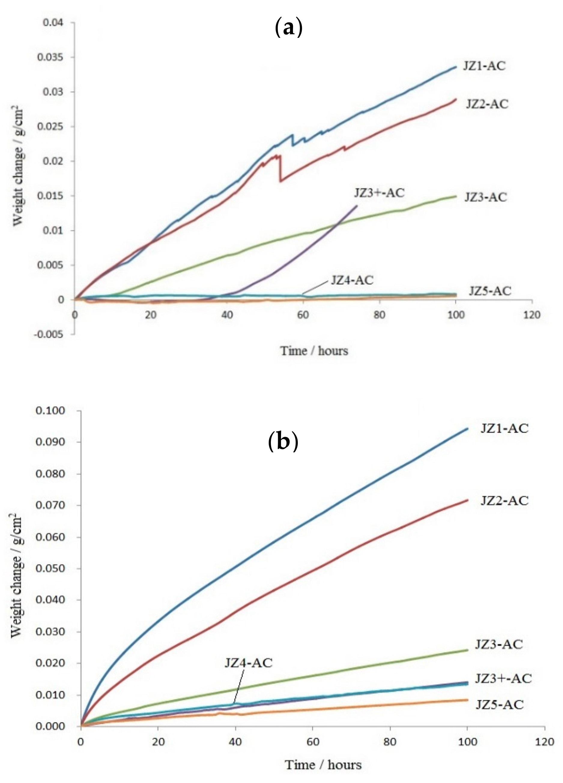
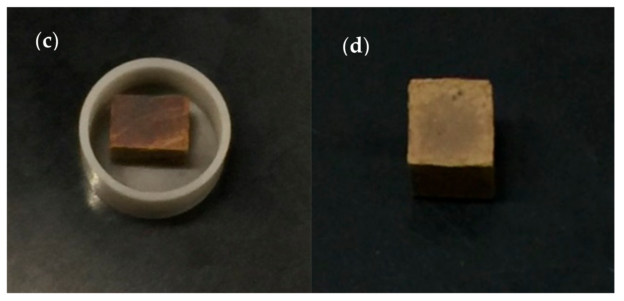
The TG data are shown in Figure 2, the oxidised specimens in Figure 3 and the rate constants and weight changes of the alloys JZ4 and JZ5 are given in the Table 3. In Figure 2, the data for the Ta-containing alloys JZ1 to JZ3+ [46,47] are included for comparison purposes. The weight gains of the alloys JZ4 and JZ5 after 100 h at 800 °C were 0.82 mg/cm2 and 0.57 mg/cm2, respectively. Pest oxidation and spallation of oxide scales did not occur. Both alloys followed parabolic oxidation kinetics at 800 °C. The oxidation of the alloy JZ4 at 1200 °C was similar to that of the alloy JZ3+ [47], and the weight gain was 13.43 mg/cm2. In the case of the alloy JZ5, the weight gain of 8.43 mg/cm2 was the lowest of all the JZ series of alloys. No spallation of the oxide scales was observed in the alloys JZ4 and JZ5.

4.2.1. Oxidation at 800 °C

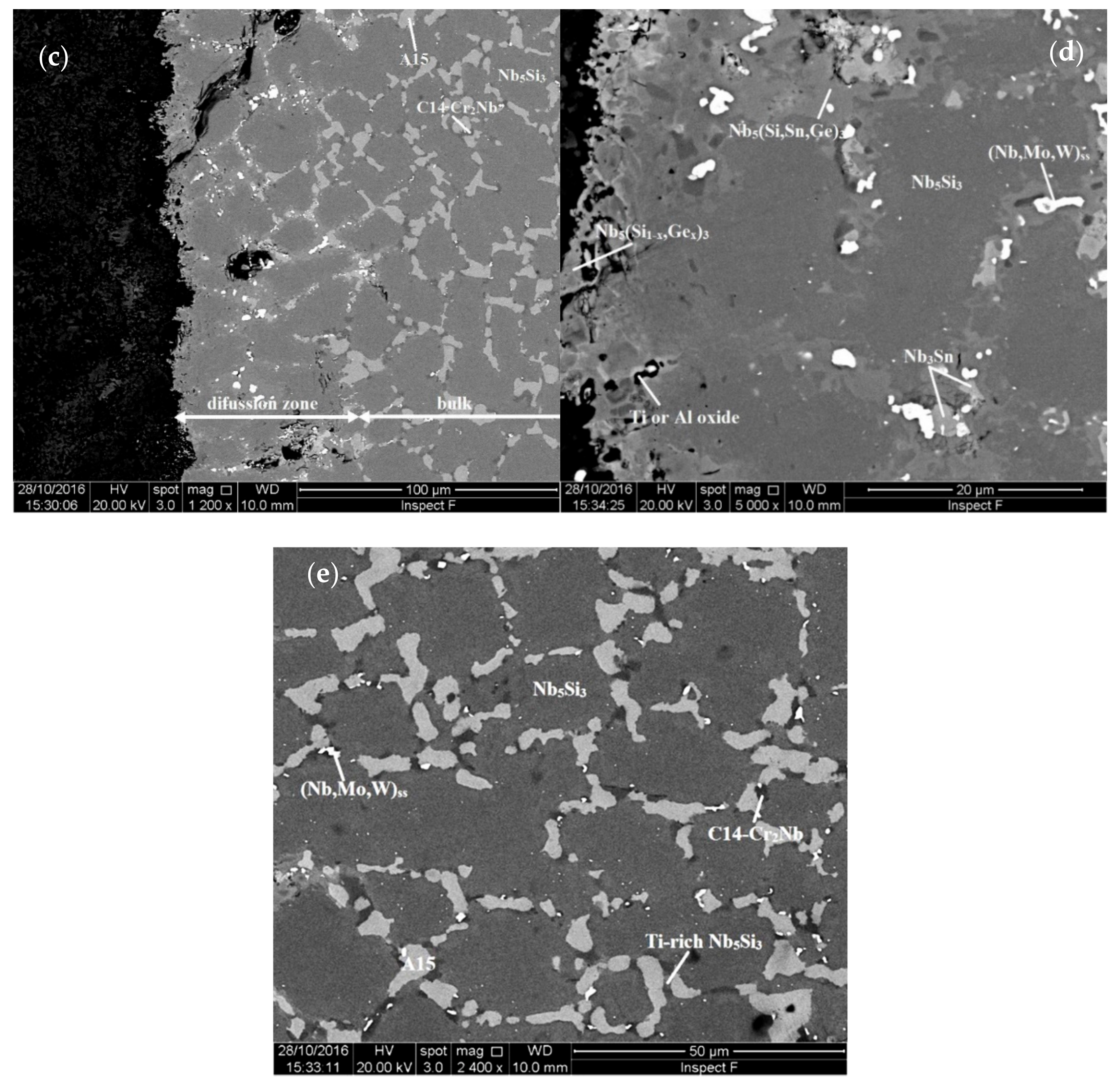
Figure 4a,b show the oxide scale and bulk of a cross section of the alloy JZ4 after the TG experiment. The thickness of the scale was about 3 μm. In the scale there were some short cracks parallel to its surface. Table S3 in the Supplementary Materials gives the chemical composition of the scale and of the phases in the bulk. The latter phases were the same as those in JZ4-AC, with the exception of the Ti-rich A15 that was not observed. There was no apparent change of the compositions of the phases compared with the JZ4-AC. The mixed oxide that formed the oxide scale was rich in Nb and Si and very lean in other elements. There was some internal oxidation in a very thin area below the scale where the oxidised A15 phase exhibited a darker contrast, see Figure 4a. Below this area the microstructure was not contaminated by oxygen.
The microstructure of a cross section of the alloy JZ5 is shown in the Figure 4c,d. The thickness of the oxide scale was at about 3 μm, similar to that of the alloy JZ4. The EDS data of the scale and the phases in bulk is given in the Table S4 in the Supplementary Materials. The phases in the bulk were Nb5Si3, A15, TM5Sn2X and Cr2Nb Laves. The mixed oxide that formed the oxide scale was rich in Nb, Ti and Si. There was no significant change of the compositions of the phases in the bulk compared with JZ5-AC. There was no evidence of internal oxidation and no contamination of the phases by oxygen.

4.2.2. Oxidation at 1200 °C

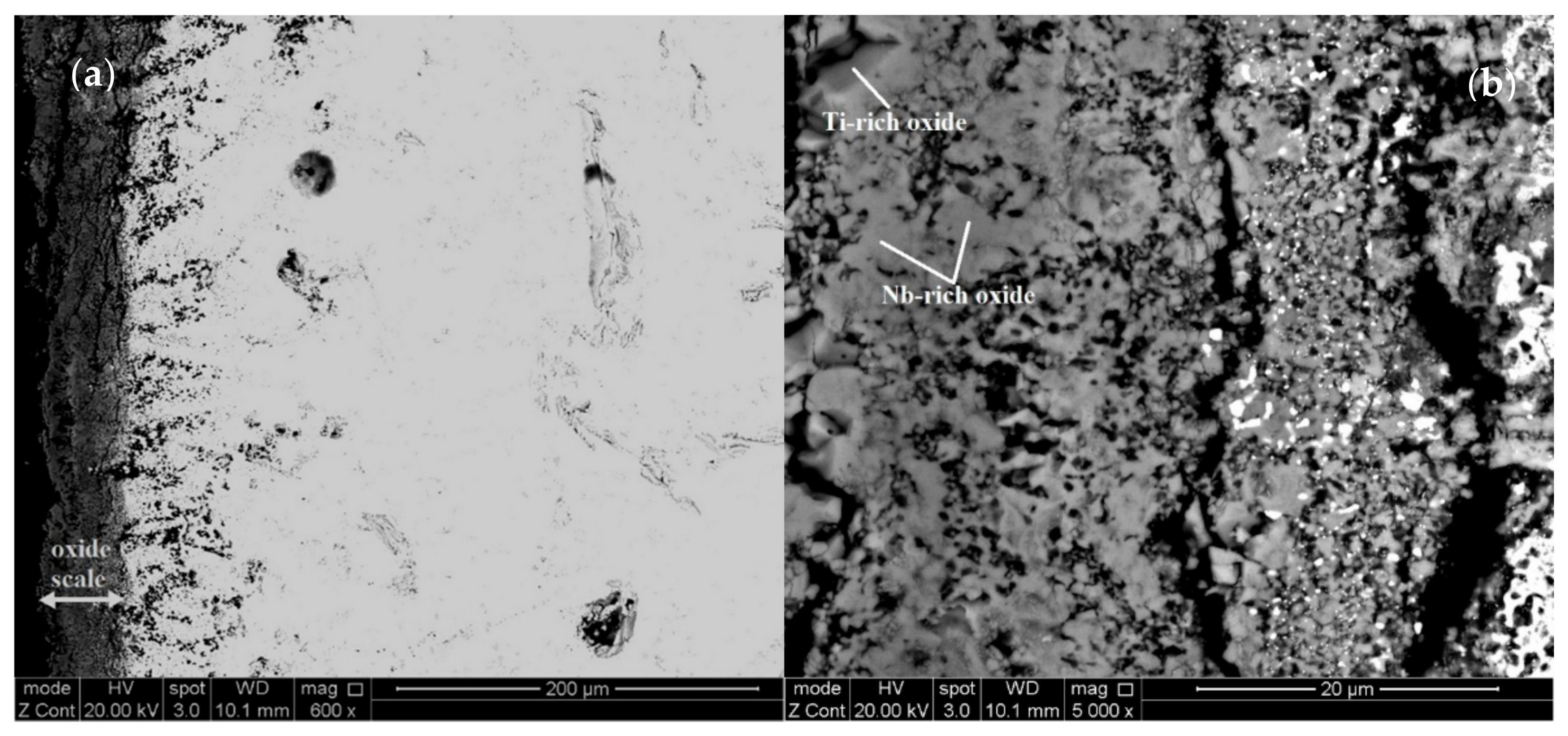
Figure 5 and Figure 6 show the microstructures of cross sections of the oxidised specimens of the alloys JZ4 and JZ5. For each alloy, three regions can be seen, namely the oxide scale, diffusion zone and bulk. The oxide scale that formed on the alloy JZ5 was significantly thinner compared with the alloy JZ4, about 50 and 200 µm, respectively. Cracks and holes were observed in the scales of both alloys.
The oxide scale of the alloy JZ4 consisted of three types of oxides, namely Nb-rich, Ti-rich (Table S5 in the Supplementary Materials) and Si-rich oxide. The latter exhibited black contrast, the same as the pores and cracks in the scale. Its concentration is not given in the Table S5. The concentrations of Sn and Ge in the scale were effectively zero. The Nb-rich oxide contained no Mo and the Ti-rich oxide contained no W. The latter oxide was richer in Al and Cr compared with the Nb-rich oxide.
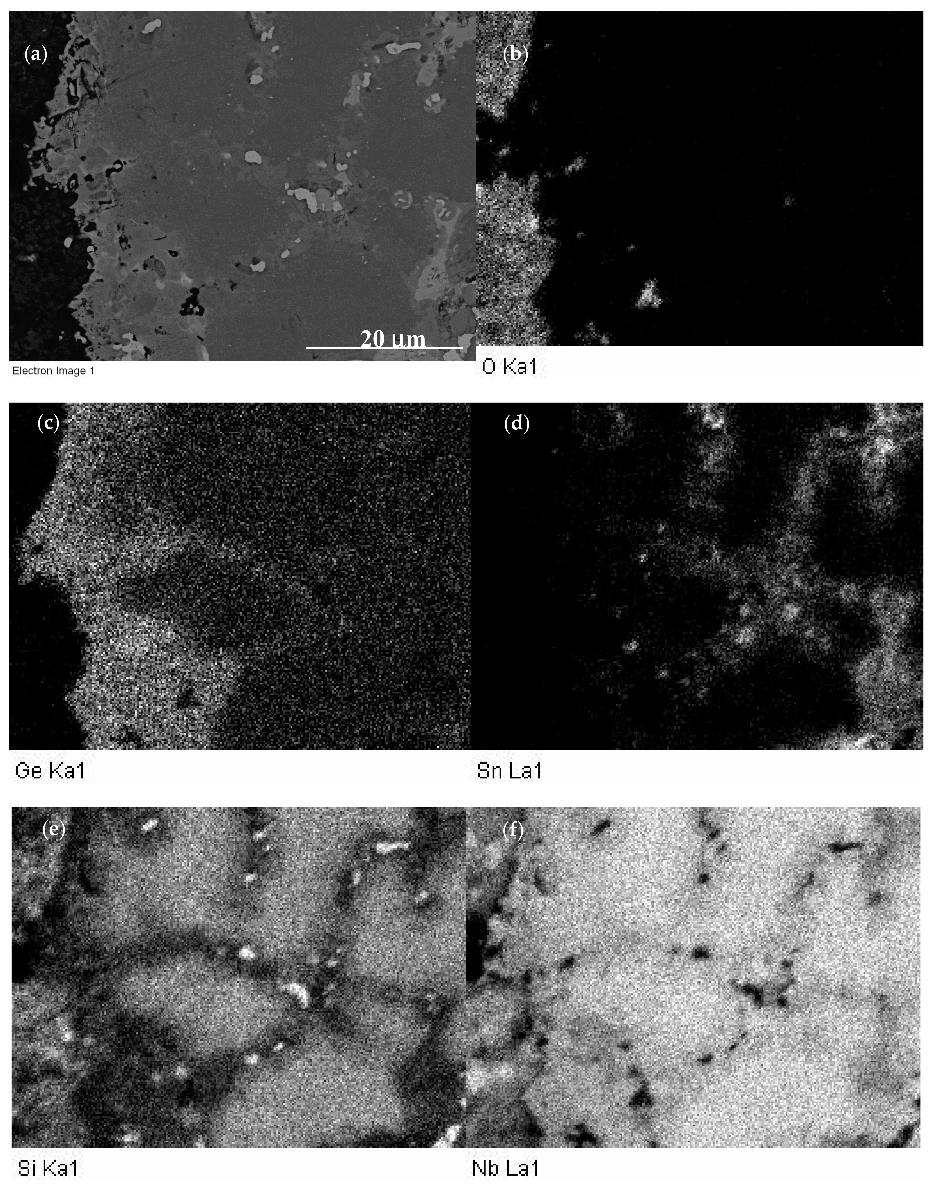
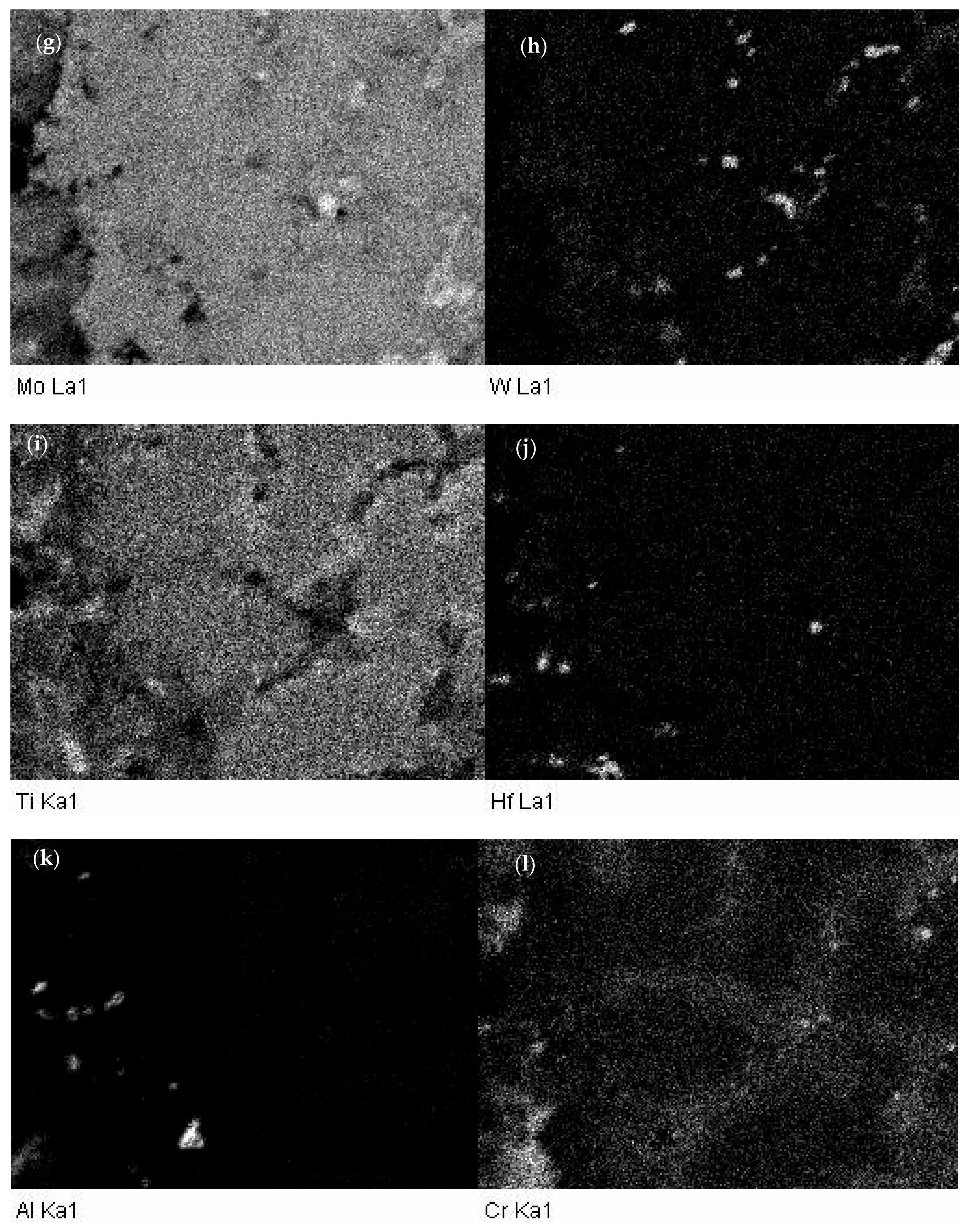
The phases in the diffusion zone of JZ4 were the Nb5Si3, Nb5(Si,Ge)3, Ge-rich Nb5(Si,Ge)3, Nb3Sn, (Nb,W)ss and HfO2 (Table S5). The Ti and Al contents in these phases remained relatively high owing to the absence of Ti and/or Al oxides in the diffusion zone. These oxides were only observed in a few areas just below the scale. Compared with JZ4-HT, the (Nb,W)ss in the diffusion zone was richer in Ge, Mo, W and poorer in Al, Cr, Ti. Compared with the solid solution in the bulk of the oxidised specimen, the (Nb,W)ss in the diffusion zone was poorer in Ti and richer in Cr, Mo, W. The bulk microstructure of the oxidised specimen was similar to that of the cast alloy and included the solid solution, which was richer in Mo, W, Al and poorer in Cr, compared with the solid solution in JZ4-HT. The concentration of Mo in the A15 was high (21.9 at.%). The Nb5Si3 and Ti-rich Nb5Si3 were poorer in Si and the latter was also poorer in W and richer in Ti and Sn compared with the cast alloy. The Laves phase was richer in Si and poorer in Al and Ti. The TM5Sn2X was not observed in the bulk after the oxidation. X-ray maps corresponding to the scale and the diffusion zone below it are shown in the Figure 7. Chromium and Ti-rich areas in the scale, corresponding to the Ti-rich oxide, can be seen in the Cr and Ti maps (Figure 7i,l). Immediately below the scale the substrate was rich in Ge (Figure 7c). Tin-rich areas can be observed below the Ge-rich area (Figure 7c,d). The Sn-rich areas, some of which were also Ge-rich, corresponded with the areas in-between Nb5Si3 grains where the A15 and the solid solution were formed (Figure 5d).
The oxides in the scale that formed on the alloy JZ5 were similar to those of the alloy JZ4 (see Table S6 in the Supplementary Materials). A solid solution rich in Mo and W was present in the inner regions of the scale, where it exhibited white contrast, see Figure 6b. The phases in the diffusion zone that formed in JZ5 were the same as those in the alloy JZ4 and the vol.% of the Ti and Al oxides was slightly increased compared with the alloy JZ4. Compared with JZ5-HT, the (Nb,W)ss in the diffusion zone was richer in Mo, W and poorer in Ti. The solid solution was also present in the bulk of the oxidised specimen but not the TM5Sn2X compound. The solid solution in the bulk of the oxidised specimen was richer in Mo, W and poorer in Al, Cr, Ti compared with JZ5-HT. The Ti-rich Nb5Si3 was richer in Ti and Sn and poorer in Si and W compared with the cast alloy. The A15 phase was richer in Mo and the Laves phase was poorer in Ti.

5. Discussion

5.1. Density

The densities of both alloys (Table 1) were (a) lower than those of the alloy JZ3+, which had the lowest density of the Ta-containing JZ series of alloys [46,47], (b) lower than the densities of Ti-free creep resistant Nb-silicide-based alloys (see Figures 2 and 4 in [1]), and (c) significantly lower than the target density (ρ = 9 g/cm3) of Nb-silicide-based alloys with RM additions and a strength of 450 MPa at 1500 °C [55].
The higher Ti concentration in the alloy JZ5 resulted in its density falling below 7 g/cm3 (Table 1). Furthermore, the density of JZ5 was lower than the density of some of the Ti-rich Nb-silicide-based alloys studied to date (Figure 5 in [1], and Table 4). The densities of the alloys JZ4 and JZ5 also satisfied the constraint (iii) in alloy design (Section 2). The data in Table 4 shows that with the exception of the RCCA alloy JZ3, the densities of all the other Nb-silicide-based alloys, which are also RCCAs, were lower than the lower density value (7.78 g/cm3) of multiphase RCCAs with bcc solid solution + M5Si3 silicide(s) in their microstructure, as reported in Table 2 in [2].

5.2. Macrosegregation

Macrosegregation of Si (MACSi) existed in both alloys, and was more severe in the alloy JZ5. MACSi has been defined as the difference between the maximum and minimum concentrations of Si in the alloy, i.e., MACSi = CmaxSi − CminSi [60]. Tin and Ge have a stronger effect on the macrosegregation of Si compared with Mo and W (Figure A1 in Appendix A), in particular Sn. MACSi increases when the parameters ΔHm/Tm (“alloy entropy of fusion”), Tmsp (melting temperature of sp electronic configuration elements) and (ΔHm/Tm)/(ΔHmsd/ΔHmsp) increase and the ratios ΔHmsd/ΔHmsp and Tmsd/Tmsp and the parameters ΔHm (“alloy enthalpy of melting”), Tm (alloy melting temperature) and Tmsd (melting temperature of the sd electronic configuration elements) decrease [60].
Data for MACSi in Ti-rich Nb-silicide-based alloys with/out Ge, Mo or Sn are compared with the alloy JZ5 in Table 5. The aforementioned trends are followed by Tm (with the exception of the alloy KZ5), ΔHm/Tm, ΔHmsd/ΔHmsp, Tmsd, Tmsp, Tmsd/Tmsp and (ΔHm/Tm)/(ΔHmsd/ΔHmsp). The alloy JZ4 had MACSi = 3 at.%, slightly lower than that of JZ3+ [47]. The MACSi values calculated by NICE were 3.7 and 5 at.%, respectively, for JZ4 and JZ5. The data for the alloys JZ1, JZ2 [46], JZ3, JZ3+ [47], JZ4 and JZ5 show that both experimental and calculated MACSi increased with decreasing Sn/Ge and Al + Cr (figures not shown). Two noteworthy results of this research are (1) that the substitution of Ta by Mo in JZ4 not only improved oxidation resistance and reduced density but also reduced MACSi and (2) that MACSi can be controlled with solute additions that play a key role in the oxidation resistance of these alloys, namely Al, Cr, Ge and Sn. The MACSi increased with the increase in the concentration of Ti in the alloy JZ5, but was lower than that of the oxidation-resistant alloy OHS1 [45].
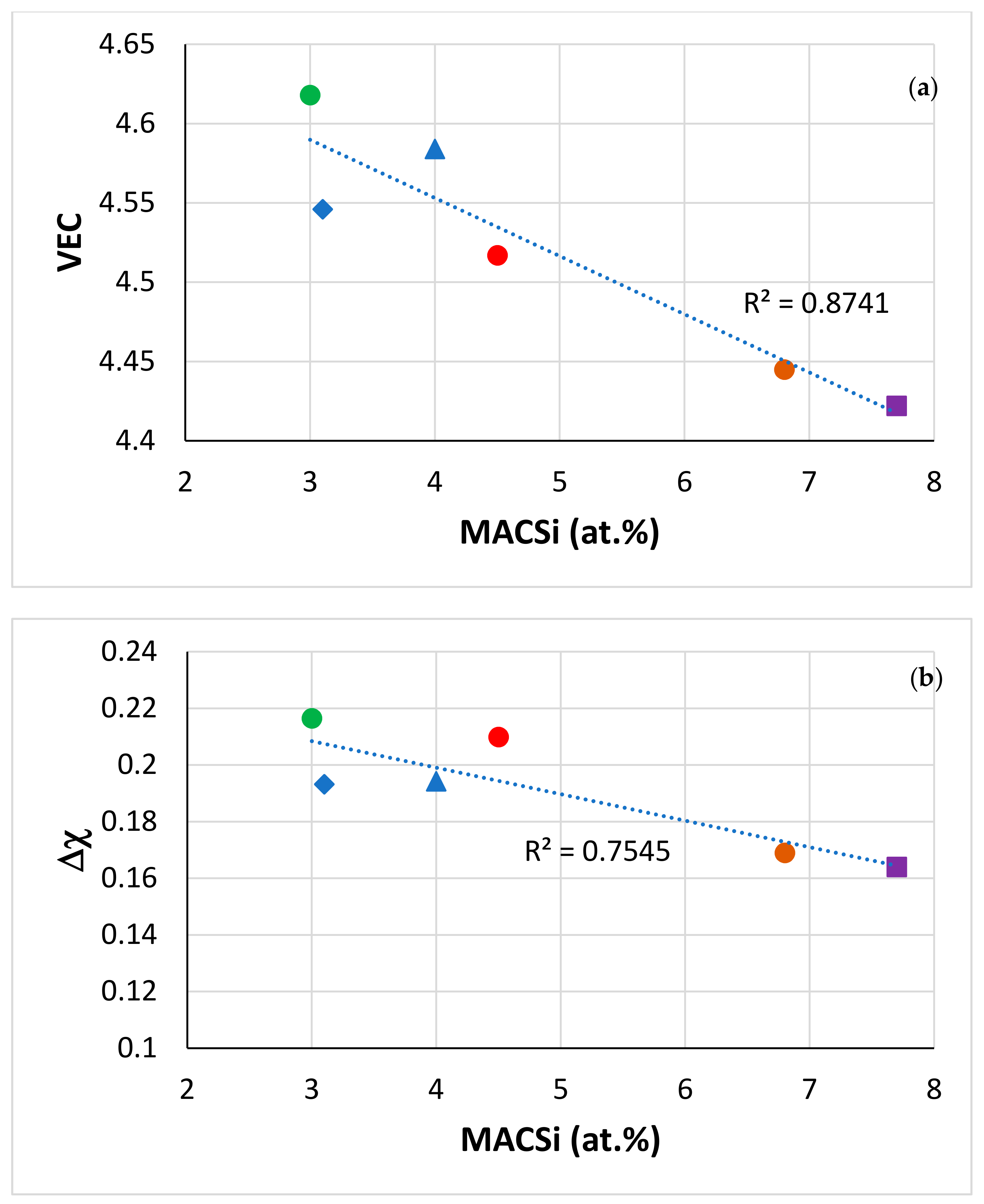
There are no data in the literature about macrosegregation of solute elements in RCCAs that were cast using arc melting or other cold hearth processes [1,2], with the exception of the RCCAs studied in our group [45,47,56,58,59]. Figure 8 shows that in RCCAs, the MACSi decreases as the alloy parameters VEC or Δχ increase (the correlation between MACSi and the alloy parameter δ is poor, figure not shown). In the Figure 8 it should be noted (i) that the solid solution was not stable in the alloys OHS1 and EZ8, (ii) that in all the alloys the Nb5Si3, A15 and C14-Cr2Nb were stable and (iii) that the solid solution was stable in the Ta or Mo containing alloys, respectively JZ3, JZ3+ [47] and JZ4, JZ5 (Table 4). It should also be noted that in the microstructures of the other RCCAs studied to date [2], stable phases were (iv) the solid solution with M5Si3 silicide, or (v) the solid solution with Laves phase, or (vi) the solid solution, with M5Si3 and Laves and (vii) that all the RCCAs did not contain A15 compound(s) [2]. On first sight it might seem strange that MACSi, which is linked with solidification conditions and solute partitioning [1,41,42,43,60,62], on which depend the chemical compositions of the phases in the as-cast microstructures, correlates with the aforementioned parameters. However, the study of the alloying behaviour of Nb-silicide-based alloys and their phases has shown (a) that the concentrations of solute elements in the Nbss, Nb5Si3, A15-Nb3X and C14-Cr2Nb correlate well with the phase parameters VEC and Δχ [21,63,64] and (b) that the phase parameters correlate well with the alloy parameters, for example Δχalloy = h(ΔχNb5Si3) [20]. It is pointed out that the trends shown in the Figure 8 should be used with caution because the data about MACSi in RCCAs are limited.

5.3. Microstructures

The actual compositions of both alloys were close to the selected compositions. Remarkably, in both alloys the Al/Cr and Sn/Ge ratios were the same as in OHS1, JZ3 and JZ3+, and in the alloy JZ4 the Mo/W and Ti/Hf ratios were similar to those in JZ3 and JZ3+ [45,46,47].
In both alloys, the “architecture” of the cast microstructure was the same. Furthermore, the microstructure of the alloy JZ5 was slightly coarser. The solid solution was not observed in the as-cast buttons of both alloys but was stable after the heat treatment. In the interdendritic areas of the primary Nb5Si3, the A15-Nb3X, C14-Cr2Nb and TM5Sn2X were formed. Note that the latter compound was not observed in the Ta-containing JZ series of alloys [46,47]. The primary Nb5Si3 was not facetted, in agreement with [6,59]. It is concluded that the substitution of Ta by Mo did not destabilise the A15 and Laves phases, decreased the vol.% of the A15, particularly in the alloy JZ4 compared with JZ3, and unlike the Ta-containing alloys JZ3 and JZ3+ [47], suppressed the solid solution in the cast microstructure and promoted the formation of TM5Sn2X in both JZ4 and JZ5. Moreover, in JZ5-AC, the increase in the Ti concentration suppressed the sensitivity of the formation of TM5Sn2X on cooling rate and increased the volume fraction of this compound, which would suggest that Ti “boosted” its formation.
The TM5Sn2X compound in both alloys is based on the Nb5Sn2Si, Ti5Sn2Si, Nb5Sn2Ge, Nb5Sn2Al compounds that all have the tetragonal W5Si3 as prototype [54,65]. The Nb5Sn2Si compound is stable at 900 °C and 1200 °C according to Sun et al. [66]. Bulanova et al. [67] reported the Ti5Si1.2–1.6Sn1.8–1.4 compound in Ti-Si-Sn alloys. With the increase in the Ti concentration in JZ5 the Ti content of TM5Sn2X also increased, as did the Ti/Nb ratio and the Al + Ge + Si content (1.17 and 12.1 at.%, and 2.96 and 14.4 at.%, respectively, in JZ4 and JZ5). The Sn content was essentially the same in both alloys (about 24.8 at.%). It should be noted (a) that the oxidation resistance of Ti-rich Nb-silicide-based alloys was improved with Ti and Mo addition [68] and was enhanced further with the addition of Hf and Sn [44,56], and (b) that this enhancement was associated with the formation of the TM5Sn2X compound at 1200 °C in the substrate just below the scale/substrate interface that has been observed in many Sn containing alloys [41,42,45,56].
In both alloys, as the primary Nb5Si3 formed, the surrounding melt became rich in Ti, Mo, W, Sn, Al and Cr. Considering the cast microstructures, in which the TM5Sn2X and C14-Cr2Nb Laves formed with small volume fractions, and that the phase with the highest melting temperature should form first, in the melt surrounding the Nb5Si3 the A15-Nb3X phase formed first followed by the C14-Cr2Nb and then the TM5Sn2X. It is suggested that in both alloys the solidification path was L → L + βNb5Si3 → L + βNb5Si3 + A15-Nb3X → L + βNb5Si3 + A15-Nb3X + C14-Cr2Nb → βNb5Si3 + A15-Nb3X + C14-Cr2Nb + TM5Sn2X. The presence of αNb5Si3 in the cast microstructures was attributed to the βNb5Si3 → αNb5Si3 transformation during solid-state cooling.
The microstructures of both the heat-treated alloys consisted of the Nb5Si3, A15-Nb3X, and Mo and W-rich solid solution (Nb,W)ss, and a very small vol.% of the C14-Cr2Nb Laves phase only in JZ4-HT. The TM5Sn2X was not stable at 1500 °C in both the alloys. The solid solutions were free of Si owing to the addition of Mo and W, which promote the formation of the Si-free Nbss [53]. It is suggested that the Nb5Si3 silicide, A15-Nb3X and the (Nb,W)ss were the stable phases in the microstructures of JZ4 and JZ5 at 1500 °C, with the C14-Cr2Nb Laves phase maybe stable only in the alloy JZ4.
Both the β and αNb5Si3 were present in the heat-treated alloys JZ4 and JZ5 (Figures S1 and S2). Molybdenum and W form, respectively, the Mo5Si3 and W5Si3, which have the D8m structure and are isomorphous with the βNb5Si3, but, unlike Ta, do not form silicides isomorphous with αNb5Si3. In the base alloy Nb-24Ti-18Si-5Al-5Cr (alloy KZ5 in [61]), the βNb5Si3 formed in the cast microstructure and both βNb5Si3 and αNb5Si3 were present after the heat treatment. The same was the case when Mo was added in the alloy Nb-18Si-5Al-5Cr-5Mo (alloy JG1 in [52]). The addition of Sn to the base alloy KZ5 promoted the βNb5Si3 → αNb5Si3 transformation upon heat treatment (alloys ZX7 and ZX8 in [41,42]) (meaning the βNb5Si3 that formed in the cast alloy transformed to αNb5Si3 after the heat treatment) but this transformation became sluggish when the base alloy KZ5 was alloyed with Ge with or without Hf (alloys ZF6 and ZF9 in [59]) (meaning that after the heat treatment both the βNb5Si3 and αNb5Si3 were present in the microstructure, as was the case in KZ5), whereas the simultaneous addition of Ge and Sn in the base alloy KZ5 stabilised the βNb5Si3 in the alloy OHS1 (meaning the βNb5Si3 → αNb5Si3 transformation did not occur upon the heat treatment [45]). Furthermore, the βNb5Si3 → αNb5Si3 transformation occurred in the case of the Al, Cr, Ge and Sn free and Ti poor alloy Nb-8.3Ti-21.1Si-5.4Mo-4W-0.7Hf buttons and suction cast bars (alloy CM1 in [62]) upon heat treatment. It is therefore likely that, owing to the simultaneous addition of Ge and Sn with Mo, W, Al and Cr, the stability of βNb5Si3 was increased in JZ4 and JZ5 compared with JZ3 and JZ3+. Could the solubility of Mo in Nb5Si3 affect the aforementioned transformation?
In as-cast and heat-treated Ti free Nb-xMo-36Si and Nb-xMo-37.5Si (x = 0 to 10 at.%) alloys that were prepared using arc melting, Sekido et al. [69] reported (a) Mo concentrations of 5.2 at.% and 3.6 at.% in βNb5Si3 and αNb5Si3, respectively, (b) that Mo stabilised the βNb5Si3, (c) that the βNb5Si3 → αNb5Si3 transformation did not occur when the concentration of Mo in Nb5Si3 exceeded 6 at.% and (d) that after heat treatment at 1400 °C for 100 h a mixture of both βNb5Si3 and αNb5Si3 were formed when the Mo concentration in the Nb5Si3 was 4 or 5 at.%. Concentrations of 2.5 at.% Mo and 0.6 at.% Mo were reported, respectively, in βNb5Si3 and αNb5Si3 for the cast and heat-treated conditions of the alloy Nb-18Si-5Al-5Cr-5Mo and slightly lower Mo concentration (1.9 at.%) in the βNb5Si3 in the cast alloy Nb-24Ti-18Si-5Al-5Cr-5Mo [52]. The above data suggest that the solubility of Mo (i) is different in βNb5Si3 and αNb5Si3, (ii) depends on the presence or not of Ti in the alloy and (iii) depends on the concentration of Mo in the alloy. In the alloys JZ4 and JZ5, where both βNb5Si3 and αNb5Si3 were present in the cast and heat-treated conditions, the average concentration of Mo in Nb5Si3 was similar to (d), namely 4.5 and 4.9 at.%, and 4.3 and 5 at.%, respectively, in the cast and heat-treated alloys JZ4 and JZ5 (Tables S1 and S2).
The solubility of W in Nb5Si3 was in the range 1 to 1.7 at.% in both the as-cast alloys, and slightly lower in JZ5-AC, and was ≤0.6 at.% after the heat treatment in both alloys. The W solubility in αNb5Si3 was reported to be about 1 at.% in Nb-W-Si alloys [70] and ≤0.6 at.% in the alloys Nb-20Si-5Hf-5W, Nb-20Si-5Mo-3W and Nb-20Si-5Hf-5Mo-3W (respectively, alloys YG5, YG6 and YG8 in [53]). Thus, the data suggest that the solubility of W in Nb5Si3 does not depend strongly on the alloying additions of Al, Cr, Ge, Mo, Sn and Ti, when the latter elements are present simultaneously in Nb-silicide-based alloys.
In both alloys there was precipitation of solid solution in the Nb5Si3 after the heat treatment (Figure 1e,f). Precipitation of Nbss in αNb5Si3 grains has been reported after the heat treatment of the alloys Nb-24Ti-18Si-5Al (alloy KZ7 in [61]), KZ5 [61], JG1 [56], Nb-24Ti-18Si-5Ge-5Al (alloy ZF5 in [71]), the arc melted button and suction cast bars of the alloy CM1 [62] after heat treatment, the large arc melted ingots of the alloy CM1 before and after heat treatment [62] and the as-cast and heat-treated OFZ bars of the alloy CM1 grown at three different growth rates [62]. In Nb-24Ti-18Si-8Cr-4Al (alloy KZ2 in [72]) only the βNb5Si3 was present in the cast microstructure and both the βNb5Si3 and αNb5Si3 after the heat treatment with Nbss precipitates in Nb5Si3 grains. For the Ti-rich Nb-silicide-based alloys Zelenitsas and Tsakiropoulos attributed this precipitation of the Nbss to the βNb5Si3 → αNb5Si3 + Nbss transformation [61].
For the Nb-xMo-36Si and Nb-xMo-37.5Si (x = 0 to 10 at.%) alloys (see above), Sekido et al. [69] reported (i) that Nbss precipitates formed in both βNb5Si3 and αNb5Si3 after heat treatment at 1300 °C for 20 h, (ii) that precipitation of Nbss in βNb5Si3 was not observed in the cast condition but after heat treatment at 1500 °C for 100 h, and (iii) that in the αNb5Si3 that formed from the βNb5Si3 → αNb5Si3 transformation after heat treatment at 1500 °C for 100 h there was Nbss precipitation in αNb5Si3. For the Nbss precipitates, two orientation relationships were observed by Sekido et al., which were in agreement with the orientation relationships reported for eutectoid Nbss/αNb5Si3 lamellae by Sekido et al. [73] and Miura et al. [74]. Sekido et al. suggested that the βNb5Si3 → αNb5Si3 transformation occurred either before the Nbss precipitated or simultaneously [69]. The results for the alloys KZ7, KZ5, JG1, ZF5 and CM1 (see the Abbreviations for the nominal compositions) are consistent with the precipitation of Nbss in αNb5Si3, whereas according to the results of Sekida et al. precipitation of Nbss is also possible in βNb5Si3. It should be noted that precipitation of Nbss was also observed in Nb5Si3 grains in JZ3-HT and [JZ3+]−HT [47] as well as in Nb5Si3 grains in the heat-treated alloys Nb-24Ti-18Si-6Ta-5Al-5Cr and Nb-24Ti-18Si-6Ta-8Cr-4Al (respectively, alloys KZ6 and KZ8 in [72]), which would suggest that Ta, similarly to Mo, promotes the aforementioned phenomenon.
The hardness of the as-cast alloys JZ4 and JZ5 was 862 HV and 838 HV, which gives room temperature strengths of 2816 MPa and 2737 MPa, and specific room temperature strengths of 387 and 396 MPa cm3g−1, respectively. After the heat treatment the room temperature strength was 2724 MPa and 2633 MPa, respectively for JZ4 and JZ5. Both the room temperature strength and specific strength were higher than other RCCAs [1,2] and comparable with those of boron containing Nb-silicide-based alloys [1].
The (Nb,Ti,Hf)3(Si,Sn,Al) and (Nb,Ti,Cr,Hf)3(Si,Sn,Al) A15 compounds have more than double the hardness of Nb3Sn (450 HV) [21]. The alloys JZ4 and JZ5 had lower vol.% A15 compared with JZ3 and JZ3+ [47], particularly the alloy JZ4, and the alloy JZ5 had lower vol.% Nbss than JZ3+. The hardness of the solid solution was the same in both alloys (850 HV) but in the alloy JZ5 the contribution to hardness of Al, Cr and Ti was 58% higher compared with JZ4 (372 HV and 236 HV, respectively (calculations used data for binary Nb-X (X = Al, Cr, Ti) from [27,31]), in other words, the smaller contribution of Mo and W to the hardness of the solid solution, owing to the lower Mo + W concentration in the (Nb,W)ss in JZ5-HT, was compensated by the higher concentrations of Al, Cr and Ti. The hardness of the Nb5Si3 was higher than that of the binary silicide [63]. In spite of the fact that the microstructures of both alloys consisted of phases that had high hardness, microcracking was not observed in the as-cast buttons and after specimen preparation. The βNb5Si3 has lower hardness and Young’s modulus and higher CTE anisotropy than αNb5Si3 and alloying with Mo reduces the CTE anisotropy [63]. To the authors’ knowledge there are no data about the effect of Ta on the CTE anisotropy of Nb5Si3. Suppression/elimination of microcracking after solidification and specimen preparation would benefit from lower CTE anisotropy, and the lower hardness of the Nb5Si3 in JZ4 and JZ5 compared with JZ3+ [47]. Precipitation of Nbss in Nb5Si3 significantly improved the toughness of the silicide in both JZ4-HT and JZ5-HT (results not shown).
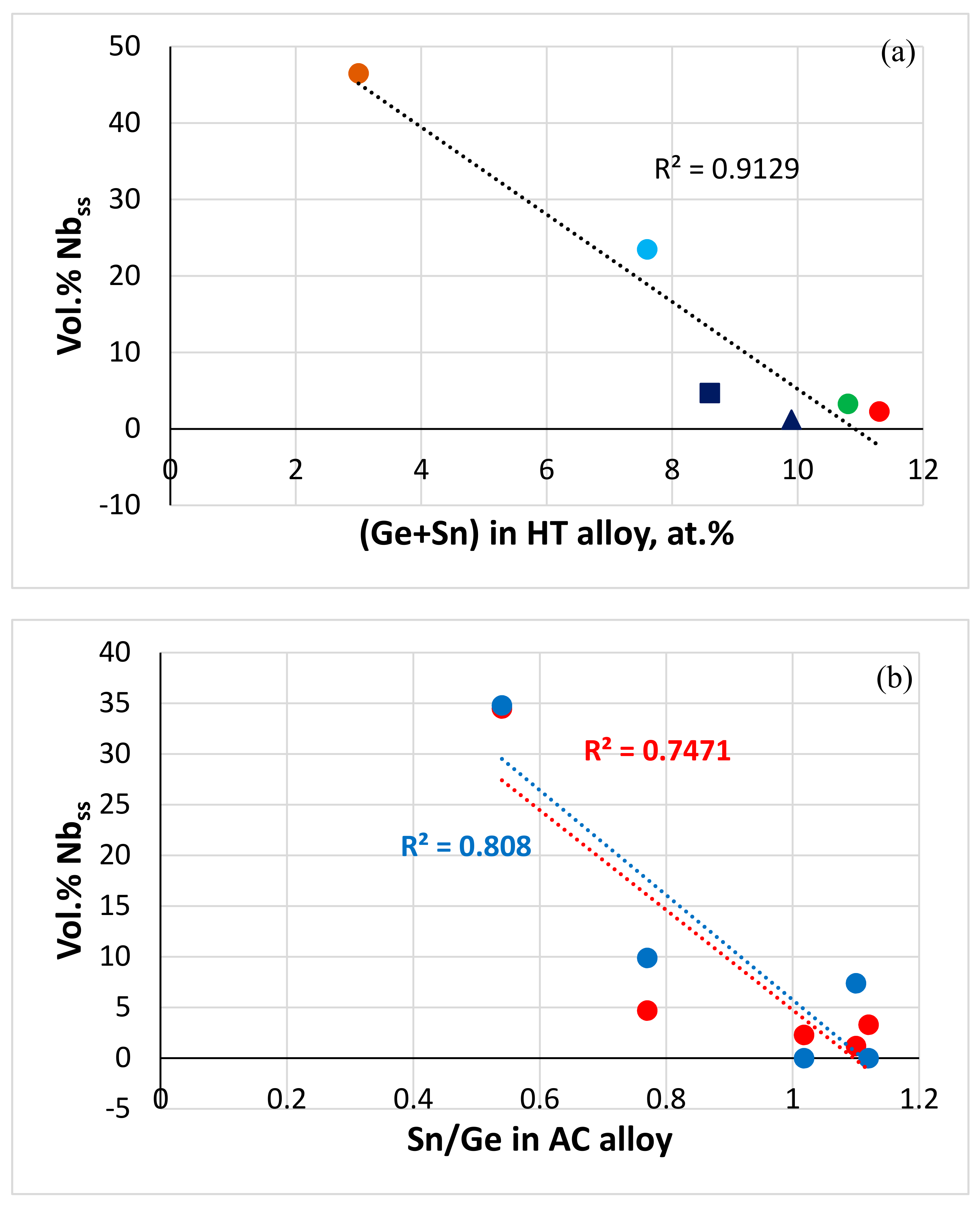
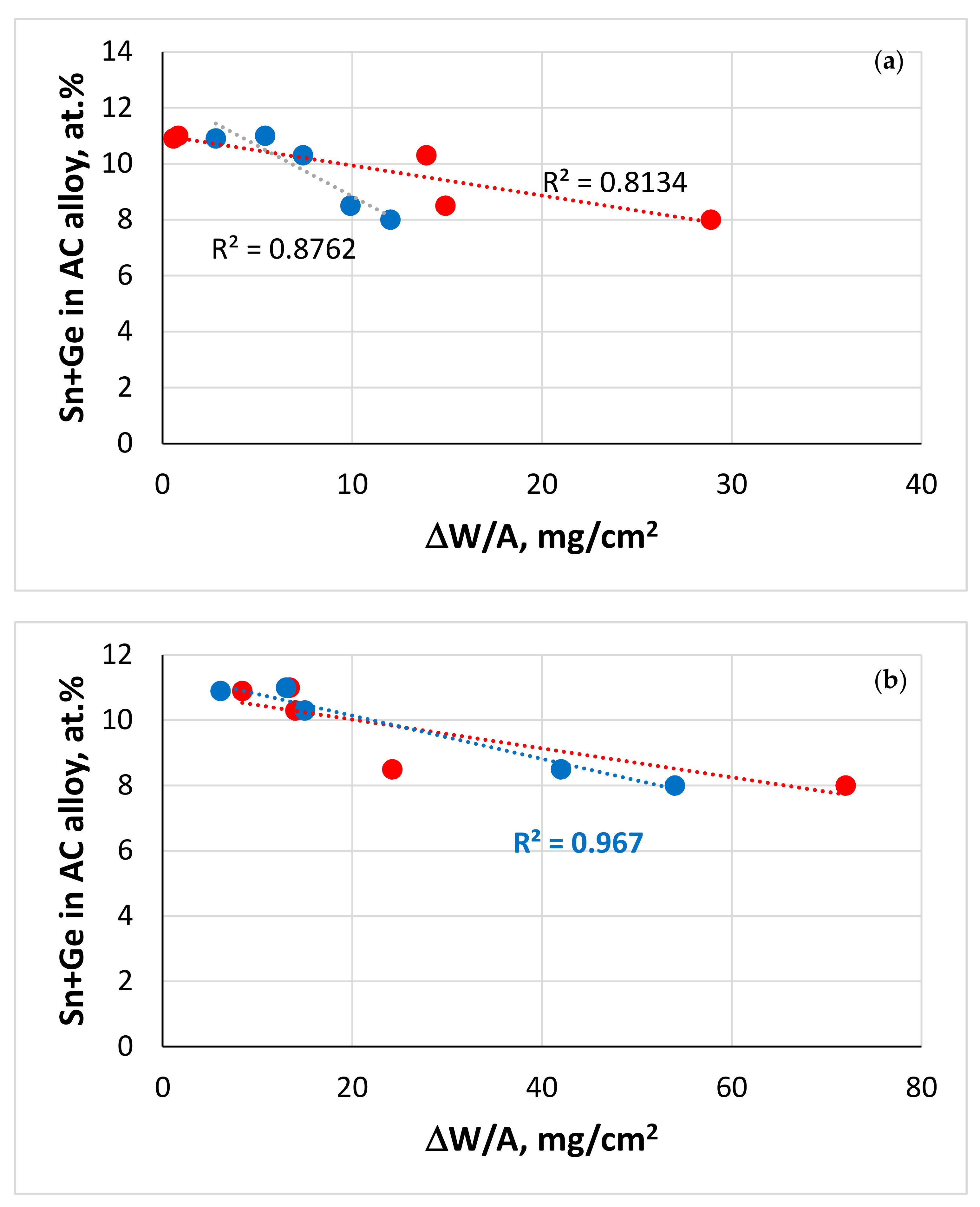
NICE [20] correctly predicted the vol.% Nbss in JZ4-AC and JZ5-AC (zero in both alloys) (Table 1) as well as the dependence of the vol.% Nbss on the Sn/Ge ratio in the cast alloys JZ2, JZ3, JZ3+, JZ4 and JZ5, although the R2 values for linear fit of data are less than 0.9 (Figure 9b). The vol.% Nbss decreased with increasing Sn/Ge ratio and Sn + Ge sum in the alloys JZ2 to JZ5 (Figure 9).
The compositions of the solid solutions in the alloys JZ4 and JZ5 that were calculated by NICE [20], respectively, were 36Nb-6.4Ti-0Si-20.2Mo-21.2W-0.7Sn-0.4Ge-0.8Hf-3.6Al-10.7Cr and 24.7Nb-10.5Ti-0Si-26.3Mo-18.8W-1.4Sn-0.6Ge-0.8Hf-4Al-12.9Cr. Compared with the experimental data (Tables S1 and S2), NICE underestimated the W and Cr, and overestimated the Nb content in the Nbss of JZ4 and underestimated the Cr and Ge, and overestimated the Nb and Mo contents in the Nbss of JZ5. Bearing in mind the accuracy of chemical analysis data and the luck of thermodynamic data for ternary systems that are relevant to the studied alloys [1,20], we consider the agreement between experimental and calculated Nbss to be good.
The parameters VEC, Δχ and δ of the Nb-silicide-based alloys and their solid solutions [7,50] are key for the calculations in NICE [20]. The experimental and calculated VEC, Δχ and δ parameters of the Nbss in JZ4, respectively, were 5.499, 0.337, 4.574 and 5.366, 0.33, 4.596, and of the Nbss in JZ5, respectively, were 5.341, 0.321, 5.463 and 5.367, 0.327, 5.09. Compared with the data for the Nbss in Nb-silicide-based alloys in [7], the data for the experimental compositions of the solid solutions show that the range of VEC is expanded from 4.4–5.4 to 4.4–5.5. The data for the alloy JZ3+ [47] showed that the range of Δχ also changed from 0.039–0.331 to 0.039–0.369. The Δχ values of the Nbss in JZ4 and JZ5 are in the latter range. In [1,7,20] it was discussed that Si-free Nbss in Nb-silicide-based alloys has δ less than approximately 5. This is supported by the results of this study.
The chemical composition of the Nb5Si3 silicide calculated by NICE [20] was 50.8(Nb, Mo, W)-9.4Ti-27.2Si-1.6Sn-5.9Ge-1.4Hf-1.9Al-1.8Cr and 44.9(Nb, Mo, W)-15.4Ti-26.5Si-1.6Sn-6.1Ge-1.9Hf-2.4Al-1.2Cr, respectively, in the cast alloys JZ4 and JZ5. Owing to the limited data about Mo and W in the NICE database, the total RM concentration was calculated instead of the concentration of each RM. Compared with the experimental data (Tables S1 and S2) NICE underestimated and overestimated, respectively, Si and Hf in the Nb5Si3 in JZ5. We consider the agreement between experimental and calculated data to be good.
The parameters VEC, Δχ, δ and the ratios sd/sp (sd electronic configuration elements over sp electronic configuration elements) and Nb/(Ti + Hf) of the alloys JZ4 and JZ5, respectively, were 4.618, 0.2165, 9.42, 1.96, 2.87 and 4.517, 0.2099, 9.66, 1.89, 1.5. The parameters VEC, Δχ and δ fall in the ranges of the parameters of Nb-silicide-based alloys [50]. NICE can calculate the creep rate due to intrinsic resistances to dislocation motion [1,20] and, together with calculations linked with oxidation behaviour, can point out whether a designed/selected alloy is worthy of further investigation after considering its creep and oxidation. The calculated creep rates at 1200 °C and 170 MPa using the above parameters and ratios were in the ranges 3 × 10⁻⁶ s−1 to 8.5 × 10⁻¹⁰ s−1, and 1.7 × 10⁻⁴ s−1 to 2.7 × 10⁻⁹ s−1, with average creep rates 4.5 × 10⁻⁷ s−1 and 2.7 × 10⁻⁶ s−1, respectively, for the alloys JZ4 and JZ5. The average creep rate of JZ4 was lower than that of JZ5, as would be expected when considering the Nb/(Ti + Hf) ratios [6]. The average creep rates were lower than the creep rate of the single crystal Ni-based superalloy CMSX-4 for the same conditions (5.6 × 10⁻⁵ s−1), but higher than the creep rate of 1 × 10⁻⁷ s−1 that is the criterion in NICE to decide whether it is likely for a designed/selected alloy to meet the creep goal [20]. However, it should be noted that the lowest values of the calculated creep rates for both alloys were lower than 1 × 10⁻⁷ s−1.

5.4. Oxidation

5.4.1. Oxidation at 800 °C

The Figure 2 and Figure 3 showed (i) that the substitution of Ta by Mo resulted in significant improvement of oxidation at 800 °C in both alloys, as did the increase in the Ti concentration in the alloy JZ5, and (ii) confirmed the beneficial effect of both Mo and Ti on the oxidation resistance of Nb-silicide-based alloys that was reported in [68].
The alloys JZ4 and JZ5 exhibited the best oxidation resistance at 800 °C (Figure 2a), gained the lowest weight compared with the alloys JZ1 to JZ3+ [46,47], the oxidation specimens retained their shapes, did not pest (Figure 3a,b) and formed thin oxide scales. Their oxidation at 800 °C followed parabolic oxidation kinetics similar to the single crystal Ni superalloy CMSX-4 that gained 0.04 mg/cm2 after 50 h and had kp = 4 × 10⁻¹⁴ g2 cm−4 s−1 [1].
Compared with the alloy JZ3 [47], the substitution of Ta by Mo in JZ4 changed the oxidation kinetics at 800 °C from linear to parabolic, decreased the weight change by 94.5% and eradicated cracks in the scale. Compared with the alloy JZ3+ the weight change decrease was similar (96%) at 800 °C and the pest oxidation was suppressed [47].
The effect of Mo with Al and Cr on the oxidation resistance at 800 °C of Nb-24Ti-18Si-based alloys without Sn and Hf additions was reported by Geng et al. [68], who showed that the addition of 2 at.% Mo was more beneficial than 5 at.%. Pest oxidation was eliminated in the Nb-24Ti-18-Si-5Al-5Cr-5Hf-5Sn-2Mo alloy with the addition of Hf and Sn. Comparison of the TG data of the JG series of alloys [56,68] and the alloys JZ1 and JZ2 [46], JZ3 and JZ3+ [47], JZ4 and JZ5 shows (i) that the beneficial effect of the synergy of Mo with Sn, Ge, Al, Cr, Ti and Hf and W was stronger than that of Ta with the same elements and (ii) that the detrimental effect of Mo addition at high concentration on the oxidation of Nb-25Ti-18Si-5Al-5Cr-based alloys was compensated with the addition of Sn and Ge with Hf, Ti and W. This is encouraging news because (a) Mo has a lower density and is a better solid solution strengthener than Ta [1,27,28,31] and (b) points to the synergy of Mo and W in Nb-silicide-based alloys and in RCCAs being more desirable than that of Ta and W for achieving a balance of strength and oxidation, and/or properties closer to the property goals [1].
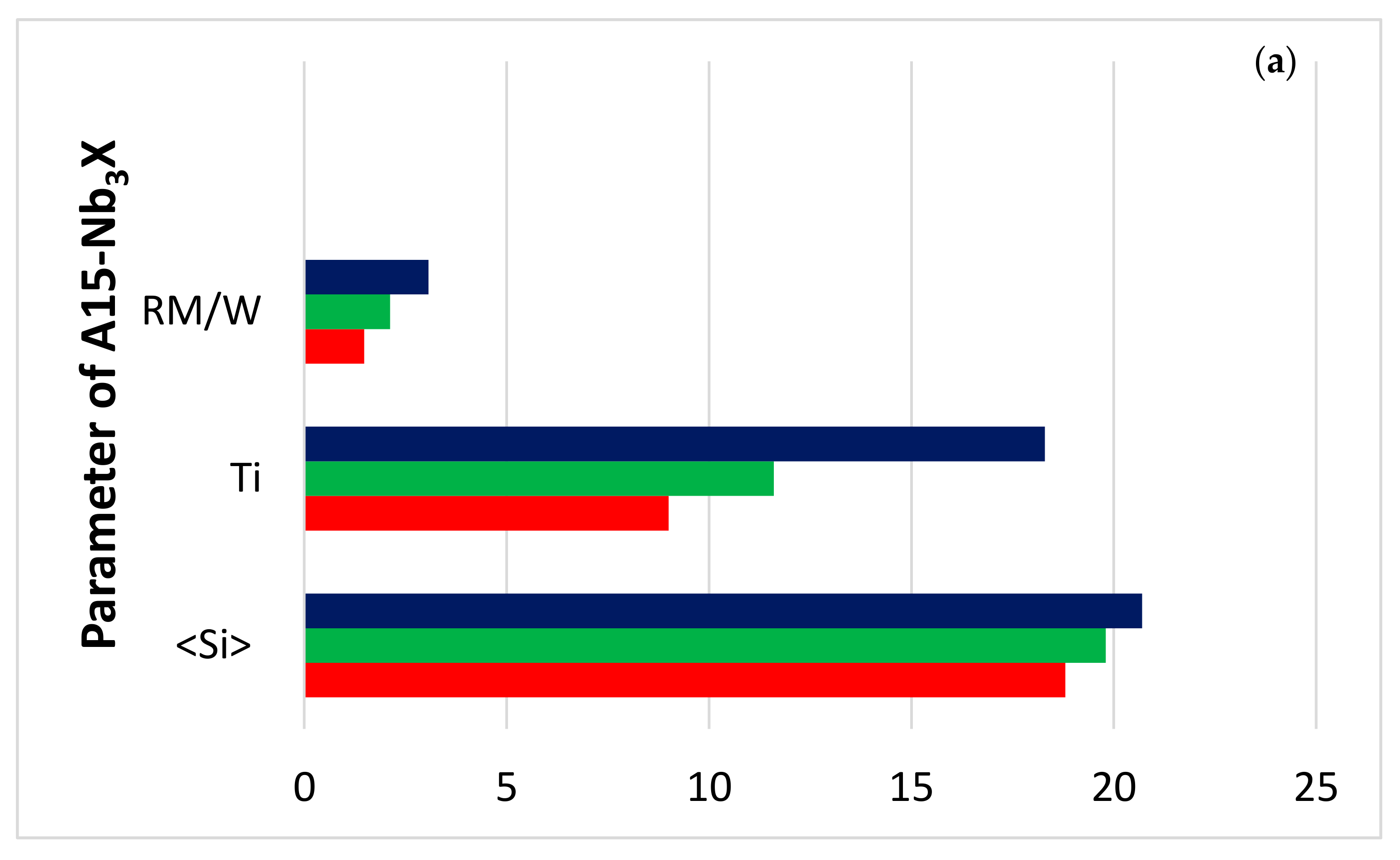
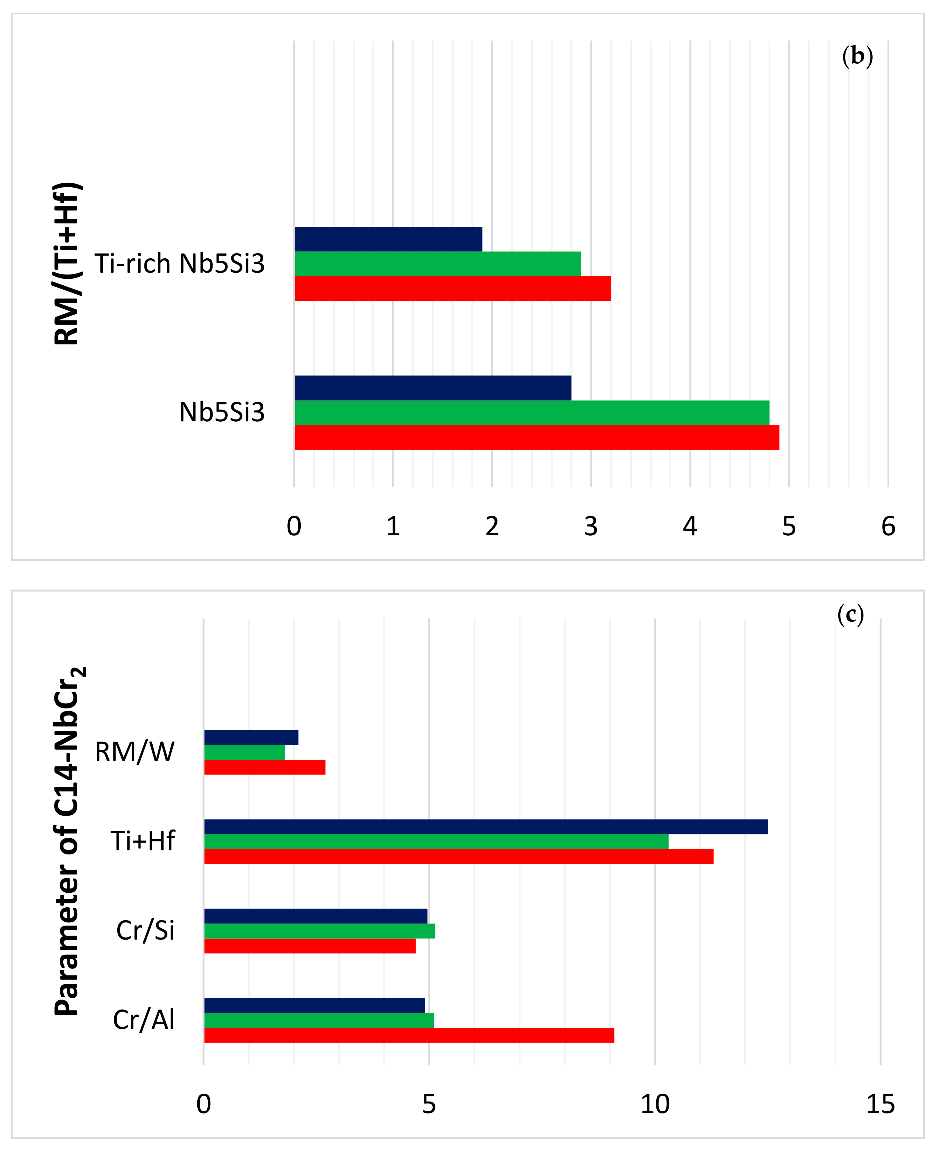
The starting microstructures of the oxidation specimens of the alloys JZ4 and JZ5 were slightly different compared with the alloys JZ3 and JZ3+, in that the TM5Sn2X compound was present and the volume fraction of the Laves phase was higher than those in the alloys JZ3 and JZ3+ [47]. The microcracking that was observed in JZ3+ was not noted in JZ4 and JZ5. There was no apparent change in the compositions of the phases in the alloys JZ4 and JZ5 after the oxidation, compared with the cast alloys. Considering the data for the composition of phases in the bulk of the alloys JZ3 [47], JZ4 and JZ5 after oxidation at 800 °C, (i) the parameters <Si>, RM/W and the Ti content of the A15 in JZ5 were the highest (Figure 10a), (ii) the RM/(Ti + Hf) ratio of the Nb5Si3 and Ti-rich Nb5Si3 were the lowest for JZ5 (Figure 10b) and (iii) the Laves phase was the poorest in Al and richest in Si in JZ3, and had the highest RM/W and Ti + Hf content, respectively, in JZ3 and JZ5 (Figure 10c). Considering that the Laves phase plays a minor role in the oxidation of Nb-silicide-based alloys at 800 °C [75] and that the TM5Sn2X compound was present only with a small volume fraction in JZ4 and JZ5, it is suggested that the good oxidation resistance of the alloys JZ4 and JZ5 at 800 °C is attributed to the low volume fraction of the A15, the absence of Nbss in the starting microstructure and the aforementioned parameters (Figure 10).
It should be noted that some of the A15 phase immediately below the oxide scale was oxidised in the alloy JZ4 (Figure 4a). This was not observed in the alloy JZ5. The better oxidation resistance of the A15 phase in the alloy JZ5 at 800 °C was attributed to the increase in its <Si> and Ti contents and the decrease in the concentration of W (Figure 10a).

5.4.2. Oxidation at 1200 °C

Compared with the alloy JZ3 [47], the substitution of Ta by Mo in JZ4 (i) changed the oxidation kinetics from linear for the majority of the duration of the oxidation experiment in JZ3 to parabolic for the whole experiment in JZ4, (ii) reduced the weight change by 44.5%, (iii) eliminated edge cracking of the scale and (iv) supressed scale spallation at 1200 °C. Compared with the alloy JZ3+ [47], (v) the weight gain of JZ4 was reduced only slightly (4%) and (vi) there was no scale spallation in JZ4 and JZ5. The reduction by 37% in the weight gain of the alloy JZ5 compared with the alloy JZ4 was attributed to the beneficial effect of the increased concentration of Ti on the oxidation resistance, in agreement with [68]. Furthermore, the increase in Ti content in JZ5 did not affect the adherence of the scale. In other words, the substitution of Ta by Mo notably improved the oxidation at both temperatures. The parabolic rate constants of the polycrystalline alloys JZ3+ [47], JZ4 and JZ5, all of which did not suffer from scale spallation, were the closest to that of the single crystal Ni superalloy CMSX-4, which gained 0.4 mg/cm2 after 50 h and had kp ≈ 4 × 10⁻¹² g2 cm−4 s−1 at 1200 °C [1].
When Sn was added (2–8 at.%) to the MASC alloy Nb-25Ti-16Si-8Hf-2Al-2Cr, all alloys gained more than 50 mg/cm2 after 50 h exposure at 1200 °C [44]. The addition of 5 at.% Sn to Nb-24Ti-18Si-2Mo-5Al-5Cr-5Hf reduced the rate constant at 1200 °C but the weight gain was high, about 90 mg/cm2 after 100 h exposure. A mass gain of about 40 mg/cm2 was observed in the alloy Nb-24Ti-18Si-5Ge-5Al-5Cr after 100 h at 1200 °C [43]. Comparison of the data of the alloys mentioned above with that for JZ3+ [47], JZ4 and JZ5 shows (1) that the oxidation resistance of Nb-silicide-based alloys at 1200 °C was enhanced dramatically when Sn and Ge were added together with Al, Ce, W and Ta or Mo, and with Hf at low (≤1 at.%) concentration and (2) that the oxidation improved with the increase in the Sn and/or Ti concentrations in the alloys.
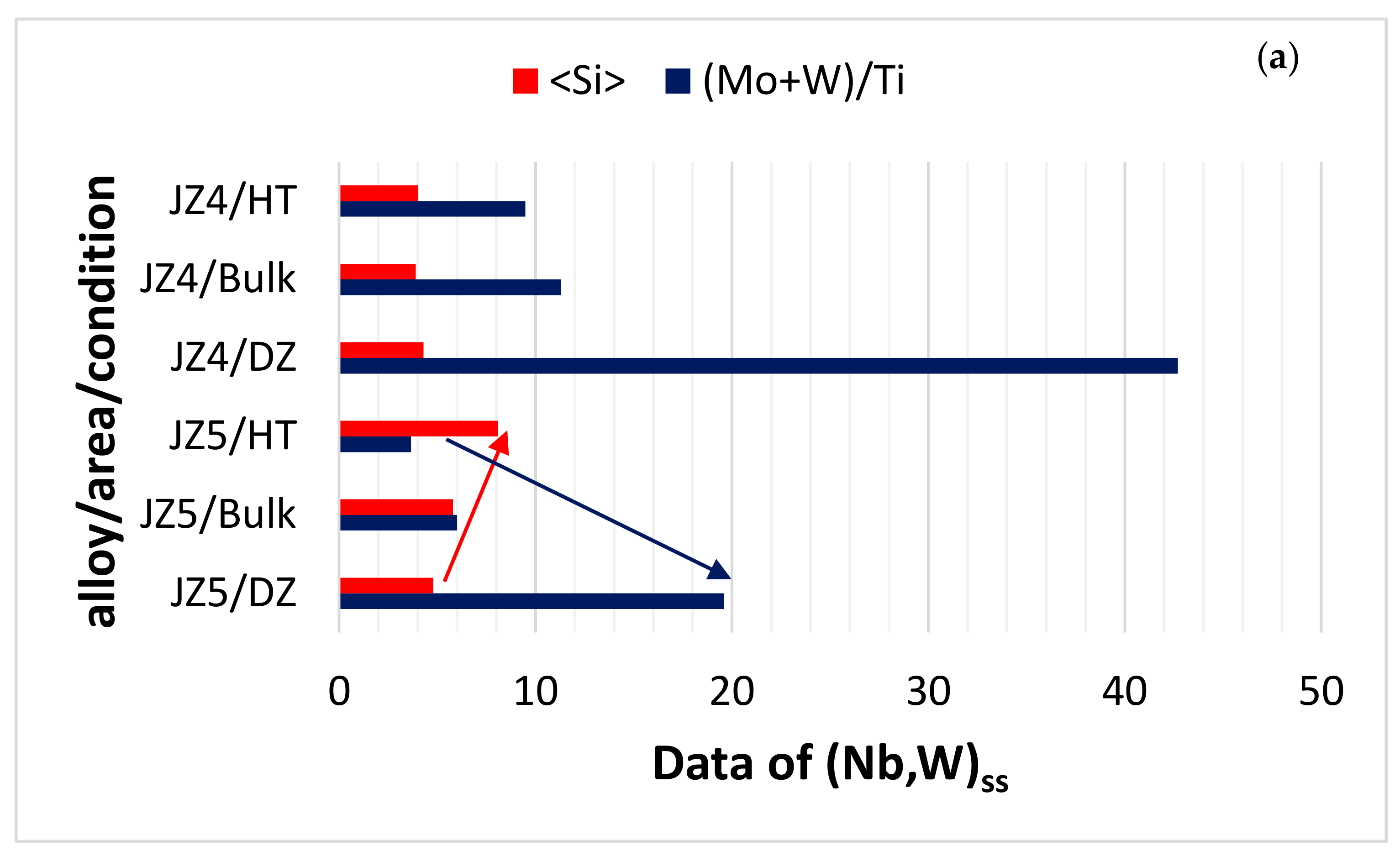
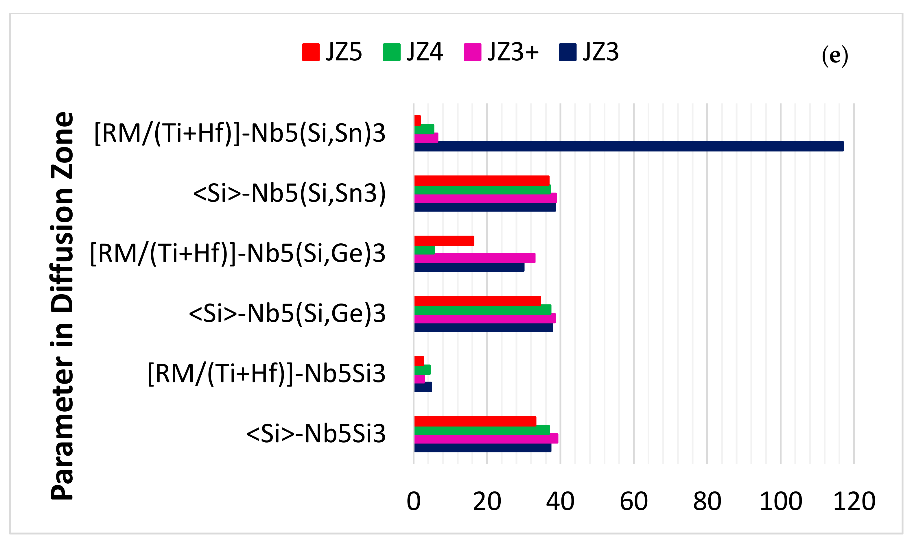
Changes in the chemical composition of the (Nb,W)ss, Nb5Si3 and A15-Nb3X phases in the diffusion zone and bulk of the oxidised specimens of the alloys JZ4 and JZ5 are compared with the bulk of the heat-treated alloys in Figure 11a–c. In both alloys, the (Mo + W)/Ti ratio of the solid solution was highest in the diffusion zone, owing to the depletion of its Ti for the formation of the Ti-rich oxide in the scale and the increase in its Mo and W contents (Tables S5 and S6 and Table 6), and the <Si> content was lowest in the diffusion zone of JZ5, which indicates a stronger contribution of Al,Ge,Si,Sn in the formation of the scale compared with JZ4, where <Si> did not change significantly (Figure 11a). Note that in Table 6, two sets of data for given for the bulk, namely data for the bulk of the oxidised specimen and below this are the data in italics for the heat-treated alloy. In both the alloys of this study, the Nb5Si3 contributed Ti and Al,Ge,Si,Sn towards the formation of the scale, the latter contribution was stronger in JZ5 compared with JZ4 (Figure 11b, Table 6). Owing to segregation of solutes in the diffusion zone, the <Si> content and the Mo/W ratio of the A15-Nb3X increased in the diffusion zone of both alloys, particularly in the alloy JZ5 that exhibited a stronger trend compared with the Ta/W ratio of the alloy JZ3 (Figure 11c,d, Table 6). Considering the alloys JZ3, JZ3+ [47], JZ4 and JZ5, the trend in the <Si> content in the diffusion zone was essentially the same, with the lowest <Si> for JZ5 (Figure 11e) and the RM/(Ti + Hf) ratio of the Nb5(Si, Sn)3 in JZ5 was the lowest owing to its high Ti and Sn concentrations (Figure 11e and Table 6). It should be noted that both Sn and Ti reduce the hardness of Nb5Si3 [63]. It is suggested that the formation of thin oxide scales with low stresses due to the growth of the oxides in the scales, the presence of Nb5(Si, Sn)3 in the diffusion zone and the low vol.% of the (Nb, W)ss contributed to increase the deformation capability of the area around the scale/substrate interface and thus improved the adhesion of the scales in the alloys JZ3, JZ3+ [47], JZ4 and JZ5, particularly in the latter three alloys.
Geng et al. [56], Vellios [76], Knittel et al. [44] and Xu et al. [41,42] reported that in their Sn-containing alloys the Sn segregated at the oxide scale/diffusion zone interface at 1200 °C where the Nb3Sn and Nb5Sn2Si compounds were formed. The latter compound is not stable at 1200 °C according to [66]. The stability of the Nb5Sn2Si compound at 1200 °C has also been confirmed in oxidised Nb-24Ti-18Si-5Al-5Cr-5Sn [42]. In other words, prior to this work, the formation of Nb5Sn2Si at 1200 °C had been confirmed only in oxidised Nb-silicide-based alloys where Al, Cr and Sn were present simultaneously, which would suggest that contamination by oxygen could stabilise this compound at the said temperature. The TM5Sn2X compound that formed in JZ4-AC and JZ5-AC was not stable in the heat-treated alloys and in the oxidised alloys at 1200 °C. This would suggest that the simultaneous addition of Ge and Sn with Mo and W was also key to TM5Sn2X not being stable at 1200 °C.
A common observation in the alloys JZ3, JZ3+ [47], JZ4 and JZ5 was the segregation of Ge and Sn below the scale/substrate interface (Figure 7) and formation of Sn and Ge containing intermetallic phases in the diffusion zone (Table 6). Segregation of solutes in the substrate just below the scale/substrate interface has been studied in [41,42,45,56,76]. Table 7 shows the solutes that are predicted to segregate to the surfaces of binary Nb-X alloys. Note that Table 7 is an expansion of the Table 7 in [41] to include data for Ge, Mo and Hf.
According to theory A, the solute of the alloy with lower heat of sublimation should segregate to the surface; according to theory B, the larger the solute atom relative to the solvent, the stronger the surface segregation; according to theory C, surface segregation should occur when, owing to solute distribution (partitioning), the melt is richer in solute than the solid, and according to theory D, the element with the lower surface energy segregates.
Ge- and Sn-containing intermetallics and Nbss rich in refractory metals formed in the diffusion zones of the alloys JZ3, JZ3+ [47], JZ4 and JZ5 at 1200 °C. The solid solution in the alloys JZ3 and JZ3+ was very rich in W and extremely poor in Ti (see Table 6 and [47]). Segregation of W or Ta to the surface is not expected in binary Nb-X (X = Ta, W) alloys.
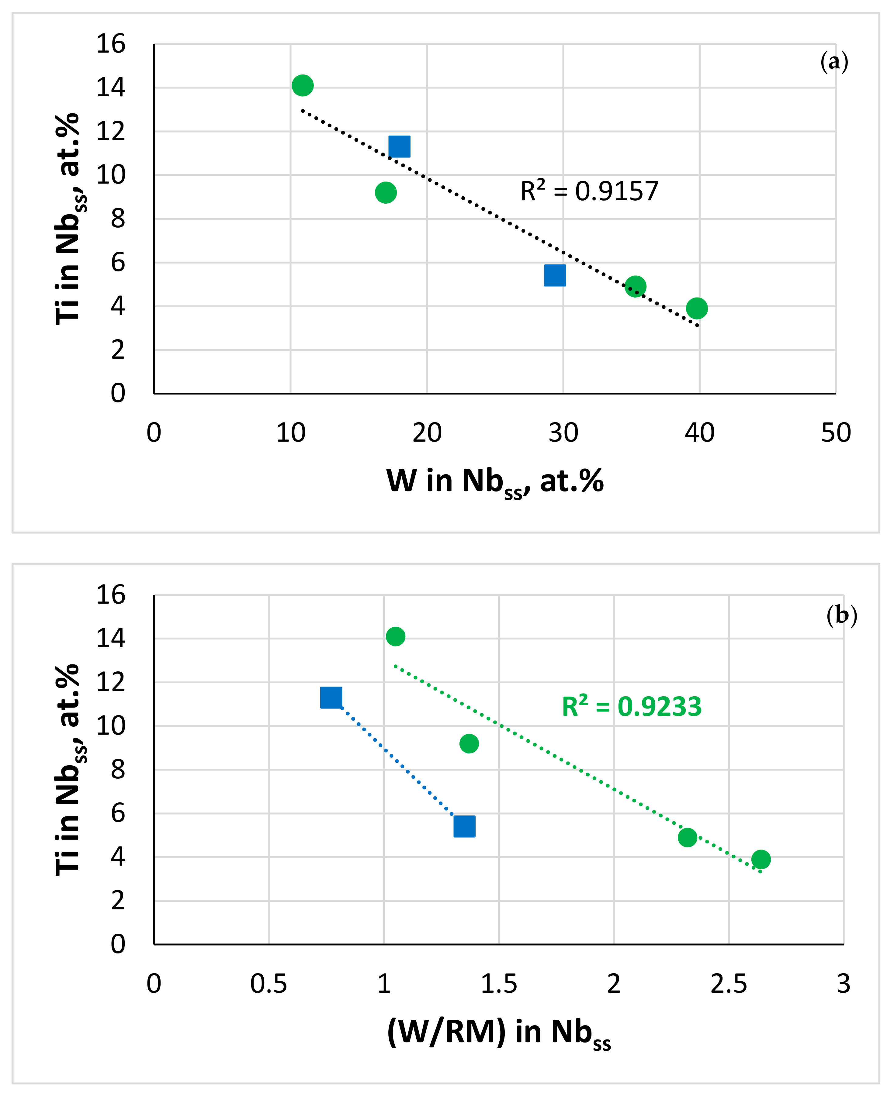
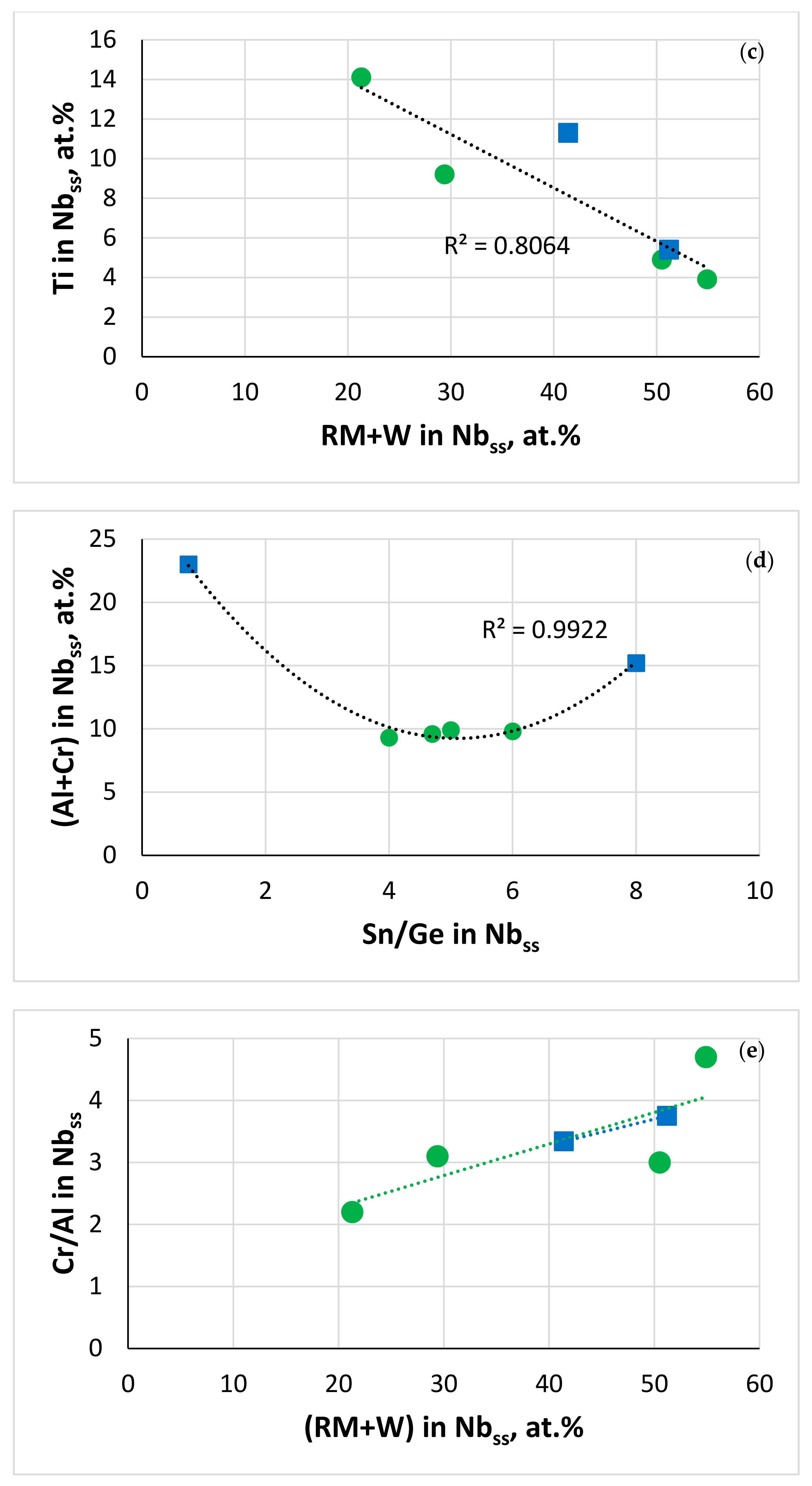
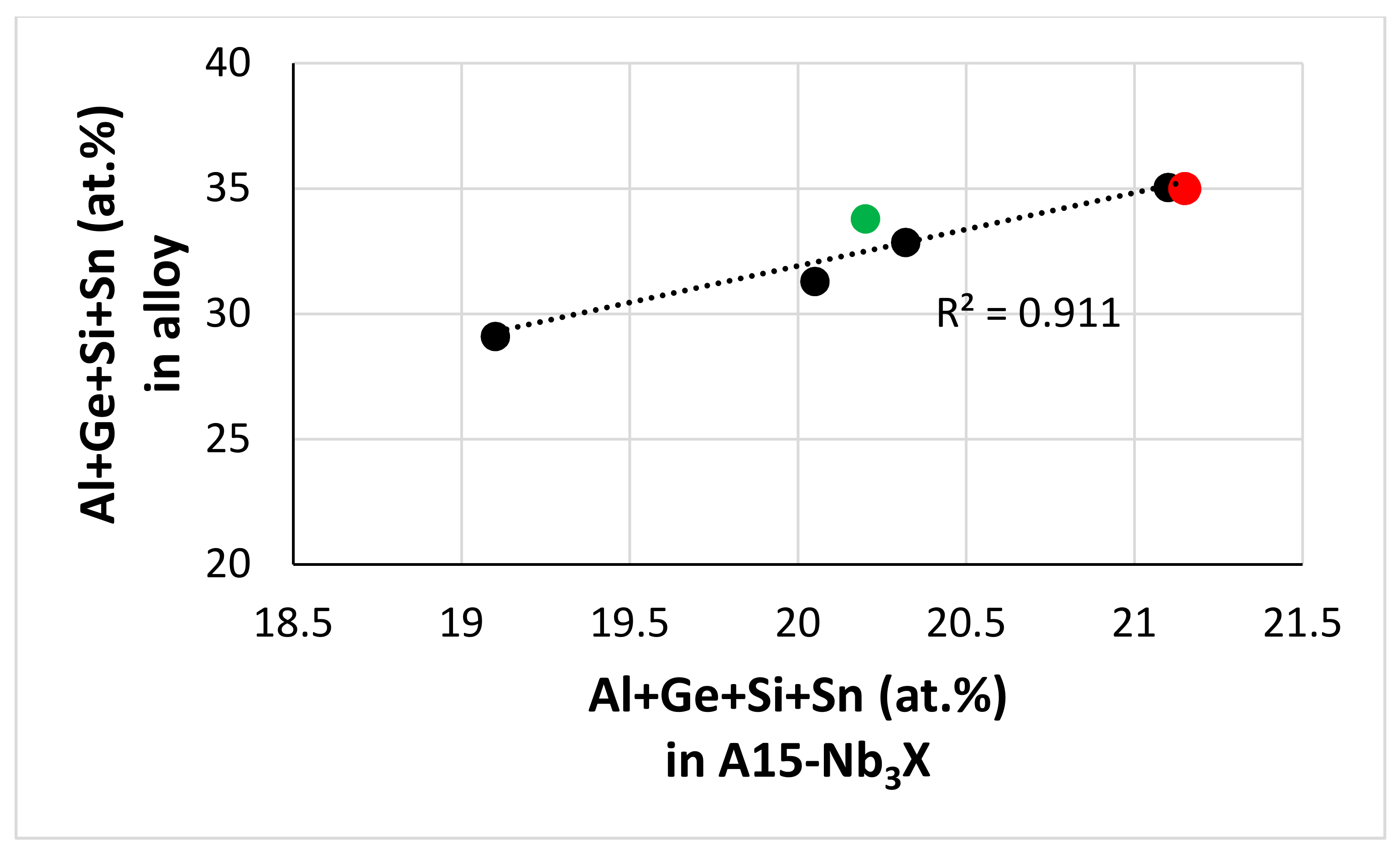
The Ti concentration in the solid solution decreased with increasing (i) W concentration [62], (ii) W/RM ratio and (iii) RM + W content (RM = Mo,Ta) (Figure 12a–c). The Al + Cr concentration of the solid solution did not depend on its Sn/Ge ratio in the Ta-containing alloys and was highest in JZ5 (Figure 12d), and the Cr/Al ratio increased with its RM + W content (RM = Mo, Ta) (Figure 12e). In the diffusion zone, as the concentration of Ti decreased in the phases owing to its consumption for the formation of the scale, in the poorer Ti solid solution the W and Mo + W contents and the W/Mo ratio increased. The Al and Cr concentrations in the solid solution were also affected, particularly in JZ4 and JZ5, where the dependence of the Al + Cr content on the Sn/Ge ratio was stronger than in the Ta-containing alloys. The Cr/Al ratio in the solid solution increased because of the increased Mo + W content, and the decrease in the Al content was more severe compared with that of Cr (Tables S5 and S6) because decrease in the Ti concentration in Nbss results to lower Al and Cr concentrations [77]. The Al + Ge + Si + Sn content of the A15 increased with that of the alloy (Figure 13). Compared with JZ5-HT, the Mo/W and Al + Ge + Si + Sn content of the A15 increased in the bulk of the oxidised alloy and its diffusion zone (Table 6) and the Mo/W ratio was higher than the Ta/W ratio of JZ3 [47] owing to the lower solubility of Ta in the A15 phase than that of Mo.
The solid solution is the Achilles heel of Nb-silicide-based alloys regarding their oxidation [68,75]. The exceptional oxidation resistance of the alloys JZ4 and JZ5 at both temperatures benefited from the very low vol.% of (Nb,W)ss that resulted from the increased Ge + Sn content in each alloy (Figure 9). The oxidation of the Nb5Si3 silicide is superior to that of Nb. One would expect the precipitation of Nbss in Nb5Si3 to decrease the oxidation resistance of the latter if it were to be contaminated by oxygen. This was not observed, as both alloys were not contaminated by oxygen after the heat treatment and after isothermal oxidation at 800 and 1200 °C. The inferior oxidation of the Ta-containing alloys JZ3 and JZ3+ [47], which also had low vol.% (Nb,W)ss, the same phases in the diffusion zone and precipitates of Nbss in Nb5Si3, would suggest that the chemical composition of the phases (Tables S3–S6 and Table 6, Figure 10, Figure 11, Figure 12 and Figure 13) played a key role regarding the control of the contamination by oxygen and the reduction of the diffusivity of oxygen in the alloys.

5.5. Further Comments on Experimental Data and NICE Calculations

The alloys JZ4 and JZ5, and the other alloys in Table 4, with the exception of JZ3+, did not pest at 800 °C. The alloys JZ4 and JZ5 followed parabolic kinetics with rate constants that were of the same order as the best Ti-rich Nb-silicide-based alloys based on KZ5 (Nb-24Ti-18Si-5Al-5Cr) (Table 3 in [1]) and two orders higher than the kp of CMSX-4 at 815 °C [1]. It is remarkable that their oxidation in the pest regime is better than that of boron containing Ti-rich Nb-silicide-based alloys that follow linear kinetics at 800 °C (Table 3 in [1]). Furthermore, it is noteworthy that the oxidation behaviour in the pest regime of all the alloys in Table 4, which are also RCCAs, is much better than that of the RCCAs that were recently reviewed in [2].
At 1200 °C, the oxidation resistance of the alloys JZ4 and JZ5 (and JZ3+) was also better than that of the other alloys in the Table 4. Both alloys (and JZ3+) followed parabolic kinetics with rate constants better than or of the same order compared with Boron containing Ti-rich Nb-silicide-based alloys (Table 3 in [1]). The alloy JZ5 exhibited the lowest kp that was two orders of magnitude higher than that of CMSX-4 at at 1200 °C.
In our opinion, it is remarkable that the two alloys of this study with (i) RM additions, (ii) low densities (albeit higher than the densities of Boron containing Ti-rich Nb-silicide-based alloys based on KZ5 (ρ ≤ 6.8 g/cm3 [1]) and (iii) probably good creep at the creep goal conditions (Section 5.3), surpass or match up with the oxidation properties of Ti-rich Nb-silicide-based alloys with or without Boron addition.
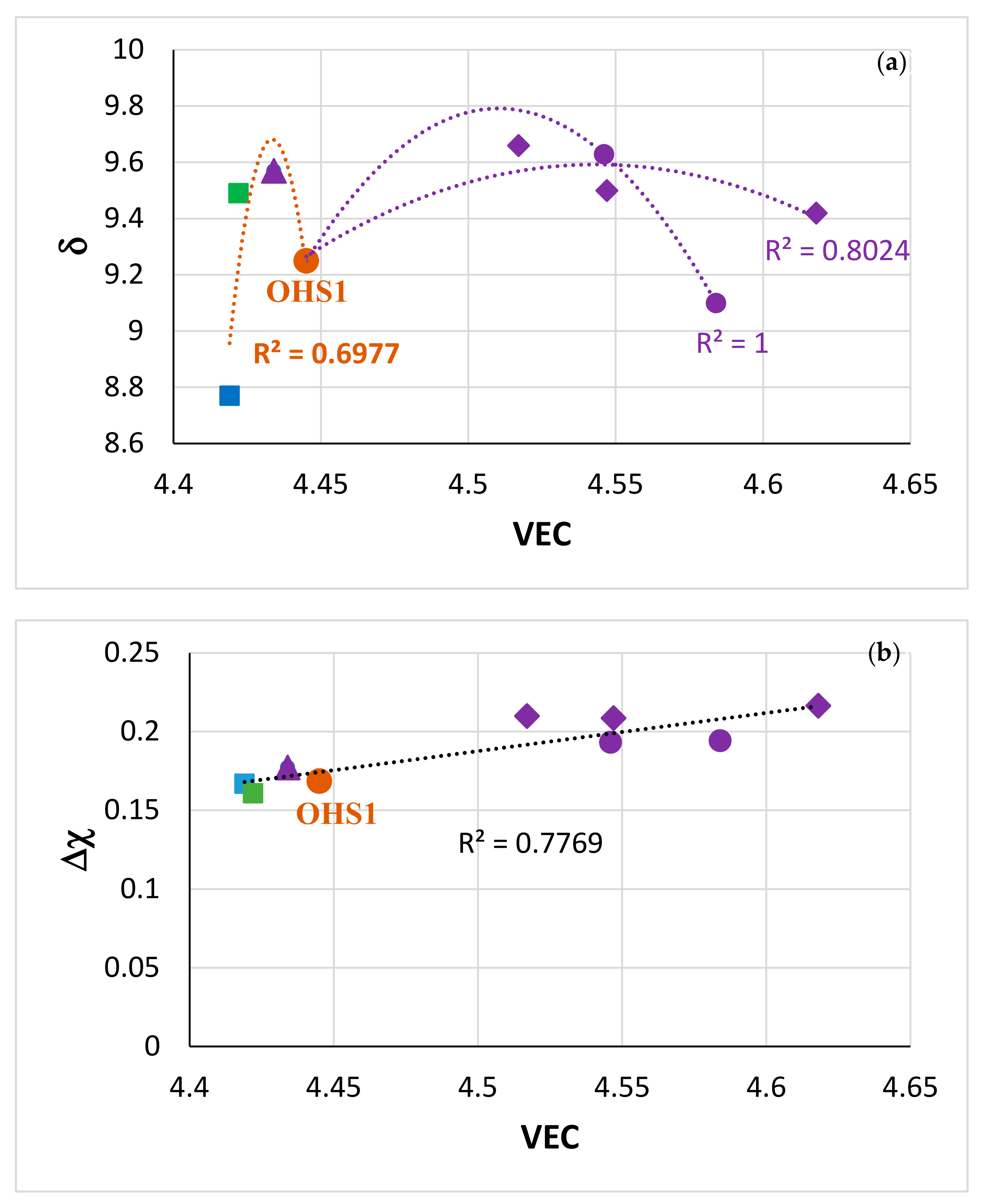
The oxidation of the alloy OHS1 [45] was the stimulus for the study of the alloys discussed in this paper (Section 1 and Section 2) and in [47]. The oxidation of JZ4 and JZ5 at 800 and 1200 °C was better than that of the alloy OHS1 (Table 4). The parameters VEC, Δχ, δ are key in the alloy design methodology NICE [20]. Maps based on these parameters describe alloying behaviour of alloys and their phases [1,7,21,47,50,63,64]. Figure 14 shows the δ versus VEC and Δχ versus VEC maps of Nb-silicide-based alloys with Ge or Sn or Ge + Sn additions and with or without RM (=Mo, Ta, W) addition. Note that the alloys included in the Figure 14 are also RCCAs. The maps in the Figure 14 clearly separate the alloys without W addition (on the left hand side of OHS1) from those with Mo and W or Ta and W addition (on the right hand side of OHS1), and show (i) that the addition of Mo, W in JZ4 and JZ5 (and of Ta, W in JZ3+) increase both VEC and δ compared with OHS1 and (ii) that all the alloys fall in the same line in the Δχ versus VEC map (Figure 14b). The latter figure also shows that the addition of Mo, W in JZ4 and JZ5 and Ta, W in JZ3 and JZ3+ increased VEC and Δχ.
Trends of the aforementioned parameters are linked with the improvement of specific properties [20], for example NICE predicts that oxidation resistance increases with decreasing VEC and increasing δ. The data in the Figure 15a are for oxidation at 800 °C and show the decrease in ΔW/A with decreasing VEC, in agreement with NICE. All the alloys in this figure are also RCCAs. The two lines, which are consistent with the linear fit of data, cross at the data point of the alloy ZF9 (Nb-24Ti-18Si-5Al-5Cr-5Ge-5Hf [43,59]). The red line is for Ti-rich Nb-silicide-based alloys. Note (i) that the simultaneous addition of Ge and Sn in OHS1 increased the weight gain at 800 °C [45] and VEC (indicated by the orange arrow) (ii) that the addition of Mo and W in JZ4 and the decrease in the Ti content, compared with OHS1, caused the clockwise shift in the map from OHS1 to JZ4, which is indicated by the green arrow, (iii) that the increase in the Ti content in JZ5 reduced both the ΔW/A and VEC compared with JZ4, which is indicated by the blue arrow and (iv) that the slope of the blue line is significantly lower than that of the red line. The data in the Figure 15b are for oxidation at 1200 °C and show the decrease in ΔW/A with increasing δ, in agreement with NICE. In this map, all the alloys fall in the same line with R2 = 0.8381. The dashed vertical and horizontal lines delineate the area of Nb-silicide-based alloys with scale spallation. Compared with OHS1, the addition of RMs in JZ3+, JZ4 and JZ5 reduced both weight gain and δ.
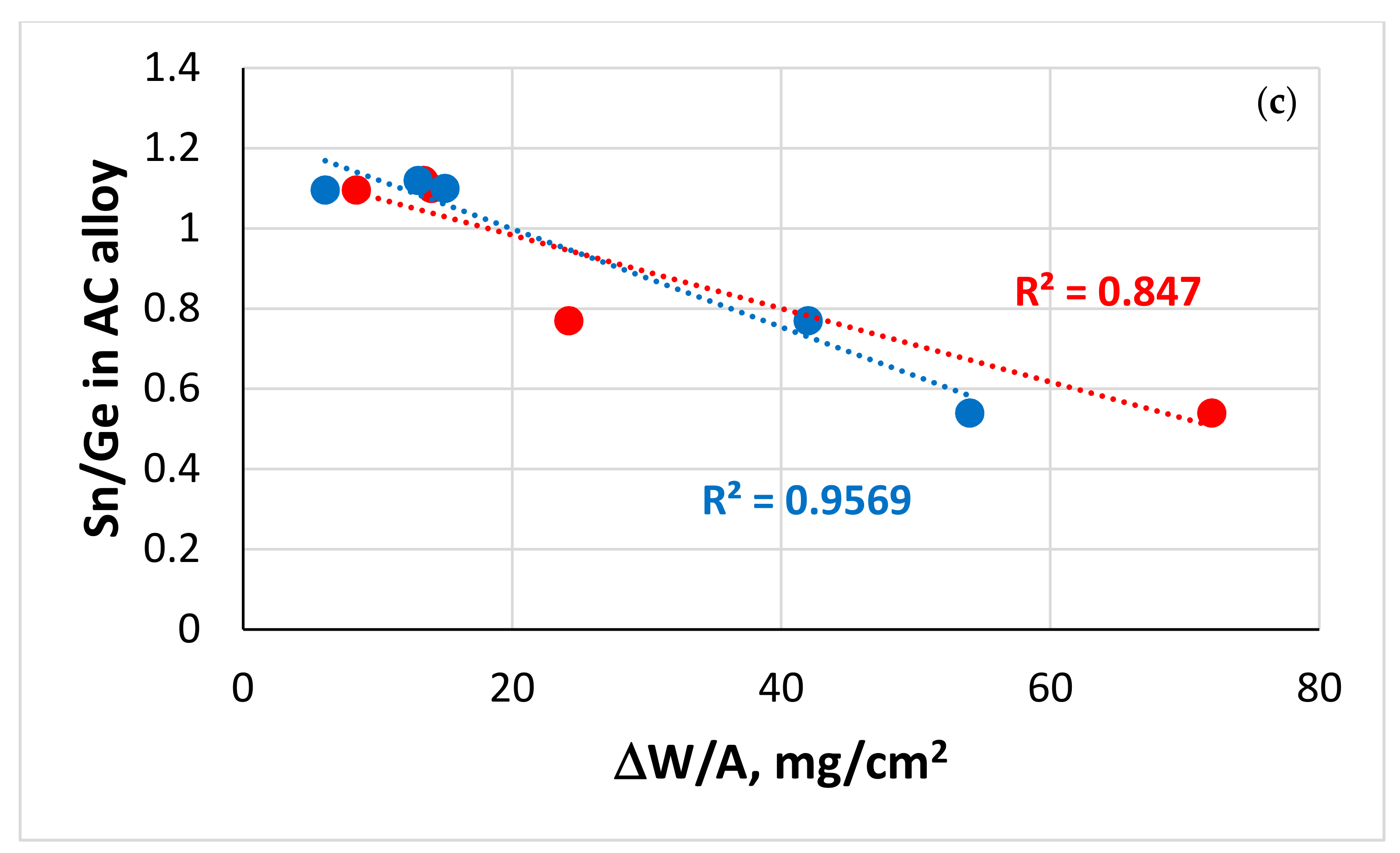
Figure 15 showed that the experimental data corroborated the trends of the parameters VEC and δ predicted by NICE for oxidation resistance in Nb-silicide-based alloys. Note that these trends were followed for alloys that are also RCCAs. Figure 16 compares the experimental data about weight change at 800 and 1200 °C with the calculated ΔW/A using NICE. The weight change decreases with the Sn + Ge content (Figure 16a,b) and the Sn/Ge ratio (Figure 16c) in the alloys. The agreement between calculations and experiment is considered good for both temperatures. Note the link between Sn + Ge or Sn/Ge with the vol.% Nbss in the alloys, and the link between the Al + Cr content in Nbss with the Sn/Ge ratio, which were discussed earlier (see also Figure 9 and Figure 12).

6. Summary, and Suggestion for Future Work

We studied the microstructures, MACSi and isothermal oxidation of the alloys JZ4 and JZ5, calculated their average creep rate due to intrinsic resistances for the creep goal conditions, and compared experimental data with the calculations of the alloy design methodology NICE. We also compared properties of the alloys with those of other RCCAs studied to date and reviewed in [2]. The densities of both alloys were less than 7.3 g/cm3 and lower than the density of multiphase RCCAs with bcc solid solution + M5Si3 silicide(s) in their microstructure. There was macrosegregation of Si in both alloys. The latter had the same phases in their as-cast microstructures, namely βNb5Si3, αNb5Si3, A15-Nb3X (X = Al, Ge, Si, Sn), TM5Sn2X (X = Al, Ge, Si), C14-Cr2Nb, and no solid solution. After the heat treatment at 1500 °C for 100 h a low volume fraction of an Mo- and W-rich solid solution was observed in both alloys together with βNb5Si3, αNb5Si3 and A15-Nb3X but not the TM5Sn2X, whereas the Laves phase was stable only in JZ4. At 800 °C both alloys did not pest, and there was no spallation of their scales at 1200 °C. At both temperatures, both alloys followed parabolic oxidation kinetics and their weight changes were lower than those of Ti-rich Nb-silicide-based alloys. The oxidation of both alloys was superior to that of other RCCAs studied to date [2]. Calculated Si macrosegregation, solid solution volume fractions, chemical compositions of solid solution and Nb5Si3, and weight changes in isothermal oxidation at 800 and 1200 °C using the alloy design methodology NICE agreed well with the experimental results.
Considering the experimental data for oxidation, MACSi and room temperature strength and the calculated data for oxidation, MACSi and creep rates of the alloys JZ4 and JZ5, it is suggested that both alloys are worthy further investigations that could consider (i) evaluation of their cyclic oxidation, (ii) assessment of their creep properties, and (iii) the scale up of alloy making to large buttons and ingots [1,62] to confirm reproducibility of properties. In our opinion, ultra-high temperature Nb-Mo-W-Ti-Cr-Hf-Al-Ge-Si-Sn RMICs, RCCAs and RHEAs are worthy of development owing to their promise to meet property goals and/or offer a balance of properties. The alloys JZ4 and JZ5 are a good basis for the design of new alloys.
In the introduction we discussed that RMICs, RCCAs and RHEAs intended for application in aero engines would require environmental coatings (ECs) of the BC/TGO/TC type [36,79]. BC Nb-Ti-Si-Al-Hf HEAs forming αAl2O3 TGO [80,81] could be suitable and compatible with Nb-Mo-W-Ti-Cr-Hf-Al-Ge-Si-Sn UHTMs. A good starting point for the design of HEA and/or “conventional” alloys for BC application in ECs could be the (Al/Si)alloy versus [Nb/(Ti + Hf)]alloy maps in Figure 13 in [81], and the Δχ versus VEC, δ versus VEC and Δχ versus δ maps in Figure 13 in [82].

Supplementary Materials

The following are available online at https://www.mdpi.com/1996-1944/13/20/4548/s1, Figure S1: X-ray diffractograms of the (a) as cast and (b) heat treated alloy, Figure S2: X-ray diffractograms of the (a) as cast and (b) heat treated alloy JZ5, Table S1: EDS analysis data (at.%) of the alloy JZ4, Table S2: EDS analysis data (at.%) for the alloy JZ5, Table S3: EDS analysis data (at.%) of phases in the alloy JZ4 after oxidation at 800 °C for 100 h, Table S4: EDS analysis data (at.%) of phases in the alloy JZ5 after oxidation at 800 °C for 100 h, Table S5: EDS analysis data (at.%) of phases in the alloy JZ4 after oxidation at 1200 °C for 100 h, Table S6: EDS analysis data (at.%) of phases in the alloy JZ5 after oxidation at 1200 °C for 100 h.

Author Contributions

Experimental work, J.Z., C.U., Supervision, C.U. and P.T., Formal analysis J.Z., C.U. and P.T., Draft preparation, J.Z., Review P.T. and C.U., Final paper, P.T., C.U., J.Z. All authors have read and agreed to the published version of the manuscript.

Funding

This research was funded by the EPSRC (EP/H500405/1, EP/L026678/1) and Rolls-Royce Plc.

Acknowledgments

The support of this work by the University of Sheffield, Rolls-Royce Plc and EPSRC (EP/H500405/1, EP/L026678/1) is gratefully acknowledged.

Conflicts of Interest

The authors declare no conflict of interest.

Abbreviations

Alloys and their nominal compositions (at.%).
CM1Nb-8.1Ti-21.1Si-5.4Mo-4W-0.7Hf
EZ8Nb-24Ti-18Si-5Al-5Cr-5Hf-5Sn
JG1Nb-18Si-5Al-5Cr-5Mo
JG2Nb-24Ti-18Si-5Al-5Cr-5Mo
JG3Nb-24Ti-18Si-5Al-5Cr-2Mo
JG4Nb-24Ti-18Si-5Al-5Cr-5Hf-2Mo
JG6Nb-24Ti-18Si-5Al-5Cr-5Hf-5Sn-2Mo
JZ1Nb-12Ti-18Si-6Ta-2.5W-1Hf-2Sn-2Ge
JZ2Nb-12Ti-18Si-6Ta-2.5W-1Hf-5Sn-5Ge
JZ3Nb-12Ti-18Si-6Ta-2.5W-1Hf-5Sn-5Ge-5Al-5Cr
JZ3+Nb-12Ti-18Si-6Ta-2.5W-1Hf-7.5Sn-5Ge-5Al-5Cr
KZ2Nb-24Ti-18Si-8Cr-4Al
KZ5Nb-24Ti-18Si-5Al-5Cr
KZ6Nb-24Ti-18Si-6Ta-5Al-5Cr
KZ7Nb-24Ti-18Si-5Al
KZ8Nb-24Ti-18Si-8Cr-4Al
MASCNb-25Ti-16Si-8Hf-2Al-2Cr
OHS1Nb-24Ti-18Si-5Al-5Cr-5Ge-5Sn
YG6Nb-20Si-5Mo-3W
ZF1Nb-18Si-5Ge
ZF5Nb-24Ti-18Si-5Al-5Ge
ZF6Nb-24Ti-18Si-5Al-5Cr-5Ge
ZF9Nb-24Ti-18Si-5Al-5Cr-5Ge-5Hf
ZX7Nb-24Ti-18Si-5Al-5Cr-2Sn
ZX8Nb-24Ti-18Si-5Al-5Cr-5Sn

Appendix A

Figure A1. Si macrosegregation (MACSi) in (a) Ti-rich (Ti concentration about 24 at.%) and (b) Ti-poor (Ti concentration about 11 at.%) Nb-silicide-based alloys. Base alloy in (a,b), respectively, KZ5 (Nb-24Ti-18Si-5Al-5Cr [1,61]) and YG6 (Nb-20Si-5Mo-3W) [1,53].
Materials 13 04548 g0a1

References

  1. Tsakiropoulos, P. Alloys for application at ultra-high temperatures: Nb-silicide in situ composites. Challenges, breakthroughs and opportunities. Prog. Mater. Sci. 2020, 100714. [Google Scholar] [CrossRef]
  2. Senkov, O.; Miracle, D.B.; Chaput, K.J.; Couzinie, J.-P. Development and exploration of refractory high entropy alloys—A review. J. Mater. Res. 2018, 33, 3092–3128. [Google Scholar] [CrossRef] [Green Version]
  3. Bewlay, B.P.; Jackson, M.R.; Gigliotti, M.F.X. Niobium Silicide High Temperature In Situ Composites. In Intermetallic Compounds—Principles and Practice; Wiley: Hoboken, NJ, USA, 2002; Volume 3, pp. 541–560. [Google Scholar]
  4. Schneibel, J.H. Beyond Nickel-Base Superalloys. In Processing and Fabrication of Advanced Materials XIII; Stallion Press: Singapore, 2005; Volume 2. [Google Scholar]
  5. Perepezko, J.H. The hotter the engine, the better. Science 2009, 326, 1068–1069. [Google Scholar] [CrossRef] [PubMed]
  6. Bewlay, B.P.; Jackson, M.R.; Zhao, J.-C.; Subramanian, P.R.; Mendiratta, M.G.; Lewandowski, J.J. Ultrahigh-Temperature Nb-Silicide-Based Composites. MRS Bull. 2003, 28, 646–653. [Google Scholar] [CrossRef]
  7. Tsakiropoulos, P. On the Nb silicide based alloys: Part I—The bcc Nb solid solution. J. Alloy. Compd. 2017, 708, 961–971. [Google Scholar] [CrossRef] [Green Version]
  8. Mendiratta, M.; Dimiduk, D. Phase relations and transformation kinetics in the high Nb region of the Nb-Si system. Scr. Met. Et Mater. 1991, 25, 237–242. [Google Scholar] [CrossRef]
  9. Kassem, M.A.; Koch, C.C. Effect of Interstitials on the Phase Stability of Selected Intermetallics. In MRS Proceedings; Cambridge University Press: Cambridge, UK, 1990; Volume 213, pp. 801–806. [Google Scholar]
  10. Jackson, M.R.; Bewlay, B.P.; Rowe, R.G.; Skelly, D.W.; Lipsitt, H.A. High-temperature refractory metal-intermetallic composites. JOM 1996, 48, 39–44. [Google Scholar] [CrossRef]
  11. Samant, A.V.; Lewandowski, J.J. Effects of test temperature, grain size, and alloy additions on the cleavage fracture stress of polycrystalline niobium. Met. Mater. Trans. A 1997, 28, 389–399. [Google Scholar] [CrossRef]
  12. Bewlay, B.; Briant, C.; Sylven, E.; Jackson, M.; Xiao, G. Creep Studies of Monolithic Phases in Nb-Silicide Based In-Situ Composites. In MRS Proceedings; Cambridge University Press: Cambridge, UK, 2000; Volume 646, p. 2.6.1. [Google Scholar]
  13. Hirai, H.; Sha, J.; Ueno, H.; Hanada, S.; Tabaru, T.; Kitahara, A. High-Temperature Compression Strength of Directionally Solidified Nb-Mo-W-Ti-Si In-Situ Composites. In MRS Proceedings; Cambridge University Press: Cambridge, UK, 2000; Volume 646, p. 5.41.1. [Google Scholar]
  14. Chan, K.S. Alloying effects on fracture mechanisms in Nb-based intermetallic in-situ composites. Mater. Sci. Eng. A 2002, A329–A331, 513–522. [Google Scholar] [CrossRef]
  15. Bewlay, B.P.; Briant, C.L.; Sylven, E.T.; Jackson, M.R. The effects of substitutional additions on creep behaviour of tetragonal and hexagonal silicides. Mat. Res. Soc. Symp. Proc. 2003, 753, BB5.24.1–BB5.24.6. [Google Scholar] [CrossRef]
  16. Chan, K.S. Cyclic-Oxidation Resistance of Niobium-Base in situ Composites: Modeling and Experimentation. Oxid. Met. 2004, 61, 165–194. [Google Scholar] [CrossRef]
  17. Xiong, B.; Cai, C.; Wan, H.; Zheng, Y. Effects of Si, W and W-Mo on isothermal oxidation behaviour of Nb/Nb5Si3 in situ composites at high temperature. J. Alloys Compd. 2009, 604, 211–216. [Google Scholar] [CrossRef]
  18. Liu, Y.; Shazly, M.; Lewandowski, J.J. Microstructural effects on crack path selection in bending and fatigue in a Nb–19Si–5Cr–3.5Hf–24Ti–0.75Sn–1W alloy. Mater. Sci. Eng. A 2010, 527, 1489–1500. [Google Scholar] [CrossRef]
  19. Zhang, S.; Guo, X. Alloying effects on the microstructure and properties of Nb–Si based ultrahigh temperature alloys. Intermetallics 2016, 70, 33–44. [Google Scholar] [CrossRef]
  20. Tsakiropoulos, P. On Nb Silicide Based Alloys: Alloy Design and Selection. Materials 2018, 11, 844. [Google Scholar] [CrossRef] [Green Version]
  21. Tsakiropoulos, P. Alloying and properties of C14-NbCr2 and A15-Nb3X (X=Al,Ge,Si,Sn) in Nb-silicide based alloys. Materials 2018, 11, 395. [Google Scholar] [CrossRef] [Green Version]
  22. Thandorn, T.; Tsakiropoulos, P. Study of the role of B addition on the microstructure of the Nb-24Ti-18Si-8B alloy. Intermetallics 2010, 18, 1033–1038. [Google Scholar] [CrossRef]
  23. Portillo, B.I.; Varma, S.K. Oxidation behaviour of Nb–20Mo–15Si–5B–20Ti alloy in air from 700 to 1300 °C. J. Alloy. Compd. 2010, 497, 68–73. [Google Scholar] [CrossRef]
  24. Zifu, L.; Tsakiropoulos, P. Study of the effects of Ge addition on the microstructure of Nb–18Si in situ composites. Intermetallics 2010, 18, 1072–1078. [Google Scholar] [CrossRef]
  25. Liu, Y.; Kramer, M.J.; Thom, A.J.; Akinc, M. Oxidation behaviour of multiphase Nb-Mo-Si-B alloys. Metall. Mater. Trans. A 2005, 36, 601–607. [Google Scholar] [CrossRef]
  26. Bewlay, B.P.; Whiting, P.W.; Davis, A.W.; Briant, C.L. Creep Mechanisms in Niobium-Silicide Based In-Situ Composites. MRS Proc. 1998, 552, KK6.11.1. [Google Scholar] [CrossRef]
  27. Begley, R.; Bechtold, J. Effect of alloying on the mechanical properties of niobium. J. Less Common Met. 1961, 3, 1–12. [Google Scholar] [CrossRef]
  28. Prokoshkin, D.A.; Vasileva, E.V. Alloys of niobium, ed. A. M. Samarin, translated from Russian by N. Kaner; translation edited by Molly Gleiser, Jerusalem. Israel Program Sci. Transl. 1965. [Google Scholar]
  29. Wilcox, B.A. Basic Strengthening Mechanisms in Refractory Metals. In Proceedings of the Refractory Metal Alloys Metallurgy and Technology; Springer Science and Business Media LLC.: Berlin, Germany, 1968; pp. 1–39. [Google Scholar]
  30. Wadsworth, J.; Nieh, T.G.; Stephens, J.J. Recent advances in aerospace refractory metal alloys. Intern. Mater. Rev. 1988, 33, 131–150. [Google Scholar] [CrossRef]
  31. Begley, R.T. Columbium alloy development at Westinghouse. In Evolution of Refractory Metals and Alloys; Dalder, E.N.C., Grobstein, T., Chen, C.S., Eds.; TMS: Warrendale, PA, USA, 1994; pp. 29–48. [Google Scholar]
  32. Bryant, R. The solubility of oxygen in transition metal alloys. J. Less Common Met. 1962, 4, 62–68. [Google Scholar] [CrossRef]
  33. Jones, D.; McQuillan, A. Magnetic susceptibility and hydrogen affinity of B.C.C. alloys of Nb-Mo Nb-Re and Mo-Re. J. Phys. Chem. Solids 1962, 23, 1441–1447. [Google Scholar] [CrossRef]
  34. Westbrook, J.; Wood, D. “PEST” degradation in beryllides, silicides, aluminides, and related compounds. J. Nucl. Mater. 1964, 12, 208–215. [Google Scholar] [CrossRef]
  35. Shah, D.M.; Anton, D.L.; Musson, C.W. Feasibility Study of Intermetallic Composites. MRS Proc. 1990, 194, 333–340. [Google Scholar] [CrossRef]
  36. Halliop, W.; McAlary, G.M.; George, R.A. Fuel Cell System with Degradation Protected Anode. WO Patent 2004012288A2, 5 February 2004. [Google Scholar]
  37. Menon, E.S.K.; Mendiratta, M.G.; Dimiduk, D.M. Oxidation behaviour of complex niobium based alloys. In Proceedings of the International Symposium Niobium 2001, Orlando, FL, USA, 2–5 December 2001; Niobium 2001 Limited: Bridgeville, PA, USA, 2002; pp. 121–145, ISBN 0971206805. [Google Scholar]
  38. Menon, E.S.K.; Mendiratta, M.G.; Dimiduk, D.M. High temperature oxidation mechanisms in Nb-silicide bearing multicomponent alloys. In Structural Intermetallics; Hemker, K.J., Dimiduk, D.M., Clemens, H., Darolia, R., Inui, H., Larsen, J.M., Sikka, V.K., Thomas, M.J., Whittenberger, D., Eds.; TMS: Warrendale, PA, USA, 2001; pp. 591–600. [Google Scholar]
  39. Jackson, M.R.; Bewlay, B.P.; Zhao, J.-C. Niobium Silicide Based Composites Resistant to Low Temperature Pesting. U.S. Patent 6,419,765, 16 July 2002. [Google Scholar]
  40. Balsone, S.J.; Bewlay, B.P.; Jackson, M.R.; Subramanian, P.R.; Zhao, J.-C.; Chatterjee, A.; Heffernan, T.M. Materials beyond superalloy-exploiting high temperature composites. In Structural Intermetallics 2001; Hemker, K.J., Dimiduk, B.M., Clemens, H., Darolia, R., Inui, M., Larsen, J.M., Sikka, V.K., Thomas, M., Whittenberger, J.D., Eds.; T.M.S. The Minerals, Metals & Materials Society: Pittsburgh, PA, USA, 2001; pp. 99–108. ISBN 0-87339-511-5. [Google Scholar]
  41. Zhen, X.; Utton, C.; Tsakiropoulos, P. A study of the effect of 2 at.% Sn on the microstructure and isothermal oxidation at 800 and 1200 °C of Nb-24Ti-18Si based alloys with Al and/or Cr additions. Materials 2018, 11, 1826. [Google Scholar] [CrossRef] [Green Version]
  42. Zhen, X.; Utton, C.; Tsakiropoulos, P. A study of the effect of 5 at.% Sn on the microstructure and isothermal oxidation at 800 and 1200 °C of Nb-24Ti-18Si based alloys with Al and/or Cr additions. Materials 2020, 13, 245. [Google Scholar] [CrossRef] [Green Version]
  43. Li, Z.; Tsakiropoulos, P. The Effect of Ge Addition on the Oxidation of Nb-24Ti-18Si Silicide Based Alloys. Materials 2019, 12, 3120. [Google Scholar] [CrossRef] [PubMed] [Green Version]
  44. Knittel, S.; Mathieu, S.; Portebois, L.; Vilasi, M. Effect of tin addition on Nb-Si based in situ composites. Part II: Oxidation behaviour. Intermetallics 2014, 47, 43–52. [Google Scholar] [CrossRef]
  45. Hernández-Negrete, O.; Tsakiropoulos, P. On the Microstructure and Isothermal Oxidation at 800 and 1200 °C of the Nb-24Ti-18Si-5Al-5Cr-5Ge-5Sn (at.%) Silicide-Based Alloy. Materials 2020, 13, 722. [Google Scholar] [CrossRef] [PubMed] [Green Version]
  46. Zhao, J.; Utton, C.; Tsakiropoulos, P. On the Microstructure and Properties of Nb-12Ti-18Si-6Ta-2.5W-1Hf (at.%) Silicide-Based Alloys with Ge and Sn Additions. Materials 2020, 13, 1778. [Google Scholar] [CrossRef] [PubMed] [Green Version]
  47. Zhao, J.; Utton, C.; Tsakiropoulos, P. On the Microstructure and Properties of Nb-12Ti-18Si-6Ta-5Al-5Cr-2.5W-1Hf (at.%) Silicide-Based Alloys with Ge and Sn Additions. Materials 2020, 13, 3719. [Google Scholar] [CrossRef]
  48. Tsakiropoulos, P. Alloys. U.S. Patent 10,227,680, 12 March 2019. [Google Scholar]
  49. Jackson, M.R.; Bewlay, B.P.; Briant, C.L. Creep Resistant Nb-Silicide Based Two Phase Composites. U.S. Patent 6,447,623.B1, 9 October 2002. [Google Scholar]
  50. Tsakiropoulos, P. On Nb silicide based alloys: Part II. J. Alloy. Compd. 2018, 748, 569–576. [Google Scholar] [CrossRef] [Green Version]
  51. MacKay, R.A.; Gabb, T.P.; Smialek, J.L.; Nathal, M.V. Alloy Design Challenge: Development of Low Density Superalloys for Turbine Blade Applications; NASA/TM-2009-215819; NASA: Washington, DC, USA, October 2009.
  52. Geng, J.; Tsakiropoulos, P.; Shao, G. The effects of Ti and Mo additions on the microstructure of Nb-silicide based in situ composites. Intermetallics 2006, 14, 227–235. [Google Scholar] [CrossRef]
  53. Grammenos, I.; Tsakiropoulos, P. Study of the role of Hf, Mo and W additions in the microstructure of Nb–20Si silicide based alloys. Intermetallics 2011, 19, 1612–1621. [Google Scholar] [CrossRef]
  54. Papadimitriou, I.; Utton, C.; Tsakiropoulos, P. Ab initio study of ternary W5Si3 type TM5Sn2X compounds (TM=Nb,Ti, X=Al,Si). Materials 2019, 12, 3217. [Google Scholar] [CrossRef] [Green Version]
  55. Fujikura, M.; Kasama, A.; Tanaka, R.; Hanada, S. Effect of Alloy Chemistry on the High Temperature Strengths and Room Temperature Fracture Toughness of Advanced Nb-Based Alloys. Mater. Trans. 2004, 45, 493–501. [Google Scholar] [CrossRef] [Green Version]
  56. Geng, J.; Tsakiropoulos, P. A study of the microstructures and oxidation of Nb-Si-Cr-Al-Mo in situ composites alloyed with Ti, Hf and Sn. Intermetallics 2007, 15, 382–395. [Google Scholar] [CrossRef]
  57. Resende, A.; Tsakiropoulos, P.; University of Sheffield, Sheffield, UK. Oxidation of Sn Containing Nb-Silicide Based Alloys. Unpublished research. 2017. [Google Scholar]
  58. Zacharis, E.; Tsakiropoulos, P.; University of Sheffield, Sheffield, UK. Development of Sn Containing Nb-Silicide Based Alloys. Unpublished research. 2011. [Google Scholar]
  59. Li, Z.; Tsakiropoulos, P. On The Microstructures and Hardness of The Nb-24Ti-18Si-5Al-5Cr-5Ge and Nb-24Ti-18Si-5Al-5Cr-5Ge-5Hf (at.%) Silicide Based Alloys. Materials 2019, 12, 2655. [Google Scholar] [CrossRef] [PubMed] [Green Version]
  60. Tsakiropoulos, P. On the macrosegregation of silicon in niobium silicide based alloys. Intermetallics 2014, 55, 95–101. [Google Scholar] [CrossRef]
  61. Zelenitsas, K.; Tsakiropoulos, P. Study of the role of Al and Cr additions in the microstructure of Nb–Ti–Si in situ composites. Intermetallics 2005, 13, 1079–1095. [Google Scholar] [CrossRef]
  62. McCaughey, C.; Tsakiropoulos, P. Type of Primary Nb5Si3 and Precipitation of Nbss in αNb5Si3 in a Nb-8.3Ti-21.1Si-5.4Mo-4W-0.7Hf (at.%) Near Eutectic Nb-Silicide-Based Alloy. Materials 2018, 11, 967. [Google Scholar] [CrossRef] [Green Version]
  63. Tsakiropoulos, P. On the Alloying and Properties of Tetragonal Nb5Si3 in Nb-Silicide Based Alloys. Materials 2018, 11, 69. [Google Scholar] [CrossRef] [Green Version]
  64. Tsakiropoulos, P. Alloying and Hardness of Eutectics with Nbss and Nb5Si3 in Nb-silicide Based Alloys. Materials 2018, 11, 592. [Google Scholar] [CrossRef] [Green Version]
  65. Papadimitriou, I.; Utton, C.; Tsakiropoulos, P. Phase equilibria in the Nb-rich region of Al-Nb-Sn at 900 and 1200 °C. Materials 2019, 12, 2759. [Google Scholar] [CrossRef] [Green Version]
  66. Sun, Z.; Guo, X.; Zhang, C. Thermodynamic modeling of the Nb-rich corner in the Nb–Si–Sn system. Calphad 2012, 36, 82–88. [Google Scholar] [CrossRef]
  67. Bulanova, M.; Tretyachenko, L.; Meleshevich, K.; Saltykov, V.; Vereshchaka, V.; Galadzhyj, O.; Kulak, L.; Firstov, S. Influence of tin on the structure and properties of as-cast Ti-rich Ti–Si alloys. J. Alloy. Compd. 2003, 350, 164–173. [Google Scholar] [CrossRef]
  68. Geng, J.; Tsakiropoulos, P.; Shao, G. Oxidation of Nb–Si–Cr–Al in situ composites with Mo, Ti and Hf additions. Mater. Sci. Eng. A 2006, 441, 26–38. [Google Scholar] [CrossRef]
  69. Sekido, N.; Hildal, K.; Sakidja, R.; Perepezko, J. Stability of the Nb5Si3 phase in the Nb–Mo–Si system. Intermetallics 2013, 41, 104–112. [Google Scholar] [CrossRef]
  70. Ma, C.L.; Li, J.G.; Tan, Y.; Tanaka, R.; Hanada, S. Microstructure and mechanical properties of Nb/Nb5Si3 in situ composites in Nb-Mo-Si and Nb-W.-Si systems. Mater. Sci. Eng. A 2004, 386, 375–383. [Google Scholar] [CrossRef]
  71. Li, Z.; Tsakiropoulos, P. The microstructure of Nb-18Si-5Ge-5Al and Nb-24Ti-18Si-5Ge-5Al in situ composites. J. Alloys Compd. 2013, 550, 553–560. [Google Scholar] [CrossRef]
  72. Zelenitsas, K.; Tsakiropoulos, P. Study of the role of Ta and Cr additions in the microstructure of Nb–Ti–Si–Al in situ composites. Intermetallics 2006, 14, 639–659. [Google Scholar] [CrossRef]
  73. Sekido, N.; Kimura, Y.; Miura, S.; Wei, F.-G.; Mishima, Y. Fracture toughness and high temperature strength of unidirectionally solidified Nb–Si binary and Nb–Ti–Si ternary alloys. J. Alloy. Compd. 2006, 425, 223–229. [Google Scholar] [CrossRef]
  74. Miura, S.; Aoki, M.; Saeki, Y.; Ohkubo, K.; Mishima, Y.; Mohri, T. Effects of Zr on the eutectoid decomposition behaviour of Nb3Si into (Nb)/Nb5Si3. Metall. Mater. Trans. 2005, 36, 489–496. [Google Scholar] [CrossRef]
  75. Zelenitsas, K.; Tsakiropoulos, P. Effect of Al, Cr and Ta additions on the oxidation behaviour of Nb–Ti–Si in situ composites at 800 °C. Mater. Sci. Eng. A 2006, 416, 269–280. [Google Scholar] [CrossRef]
  76. Vellios, N. Design of Nb-Silicide Based Alloys for Aero-Engines. Ph.D. Thesis, University of Surrey, Guilford, UK, 2007. [Google Scholar]
  77. Tsakiropoulos, P.; Zelenitsas, K.; Vellios, N. Study of the effect of Al, Cr and Sn additions on the microstructure and properties of Nb silicide based alloys. MRS Proc. 2011, 1295. [Google Scholar] [CrossRef]
  78. Tankov, N.; Utton, C.; Tsakiropoulos, P.; University of Sheffield, Sheffield, UK. Unpublished research. In Progress. 2019.
  79. Zhao, J.-C.; Jackson, M.R.; Bewlay, B.P. Oxidation Resistant Coatings for Nb-Based Silicide Composites. European Patent Application EP1229146 A2, 24 January 2002. [Google Scholar]
  80. Ghadyani, M.; Utton, C.; Tsakiropoulos, P. Microstructure and isothermal oxidation of the alumina forming Nb1.7Si2.4Ti2.4Al3Hf0.5 and Nb1.3Si2.4Ti2.4Al3.5Hf0.4 alloys. Materials 2019, 12, 222. [Google Scholar] [CrossRef] [Green Version]
  81. Ghadyani, M.; Utton, C.; Tsakiropoulos, P. Microstructure and isothermal oxidation of the alumina scale forming Nb1.45Si2.7Ti2.25Al3.25Hf0.35 and Nb1.35Si2.3Ti2.3Al3.7Hf0.35 alloys. Materials 2019, 12, 759. [Google Scholar] [CrossRef] [PubMed] [Green Version]
  82. Hernández-Negrete, O.; Tsakiropoulos, P.; Negrete, H. On the Microstructure and Isothermal Oxidation at 800, 1200, and 1300 °C of the Al-25.5Nb-6Cr-0.5Hf (at %) Alloy. Materials 2019, 12, 2531. [Google Scholar] [CrossRef] [PubMed] [Green Version]
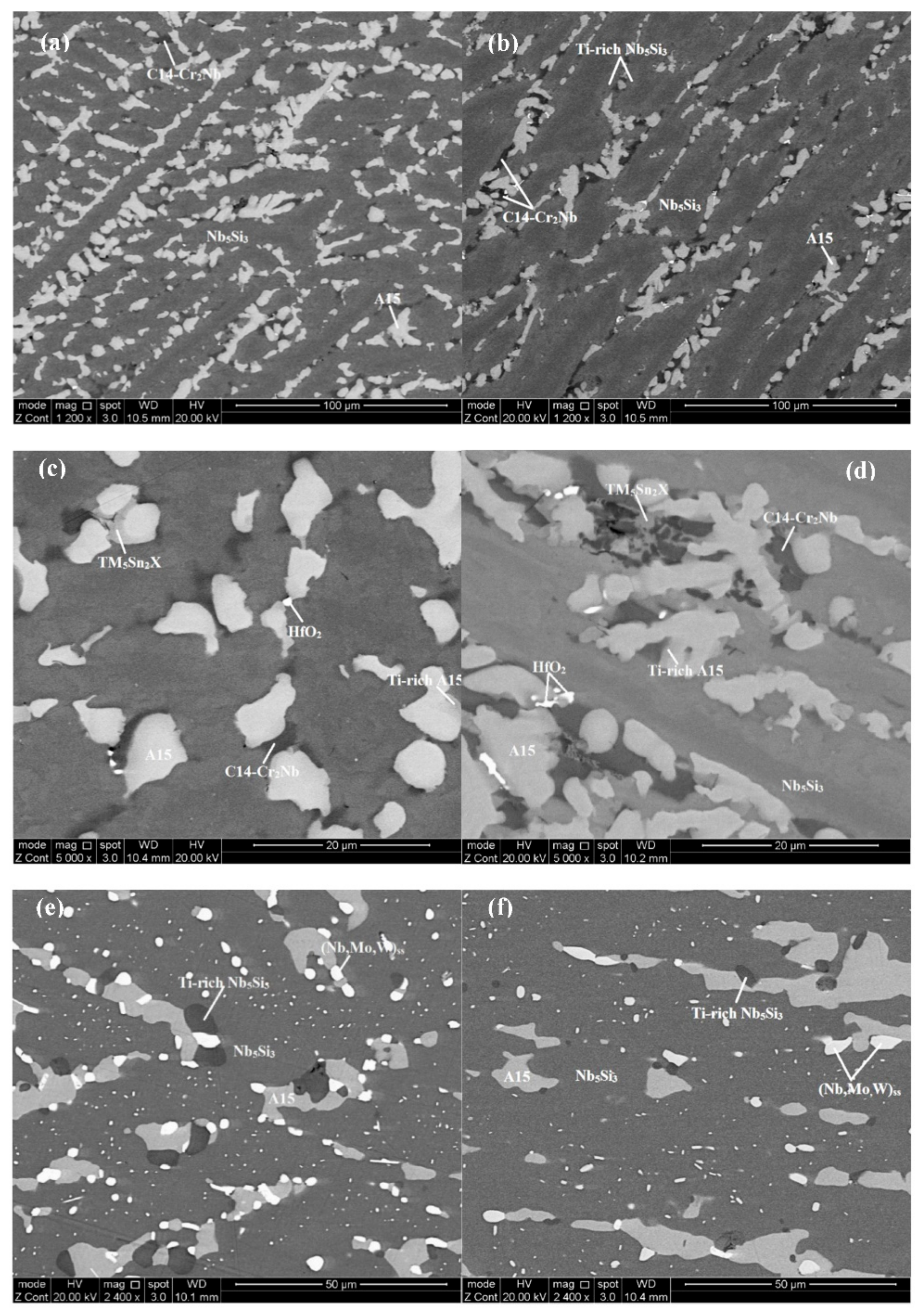
Figure 1. The as-cast (ad) and heat-treated (e,f) microstructures of the alloys JZ4 (a,c,e) and JZ5 (b,d,f).
Materials 13 04548 g001
Figure 2. Thermal gravimetric (TG) data for the isothermal oxidation of the alloys JZ4 and JZ5 together with the data for the alloys JZ1, JZ2 [46], JZ3 and JZ3+ [47]. (a) 800 °C, (b) 1200 °C.
Materials 13 04548 g002
Figure 3. The specimens of the alloys JZ4 and JZ5 after isothermal oxidation at 800 and 1200 °C; (a) and (c) alloy JZ4, (b,d) alloy JZ5; (a,b) 800 °C, (c,d) 1200 °C.
Materials 13 04548 g003aMaterials 13 04548 g003b
Figure 4. Back-scattered electron (BSE) images of the microstructure of cross sections of the oxidised alloys JZ4 (a,b) and JZ5 (c,d) at 800 °C (a,c) scale, (b,d) bulk microstructure. Enhanced contrast in (a,c) to show oxide scale.
Materials 13 04548 g004aMaterials 13 04548 g004b
Figure 5. BSE images of the microstructure of a cross section of the oxidised alloy JZ4 at 1200 °C, (a) oxide scale and microstructure below it, (b) oxide scale, (c) diffusion zone and bulk, (d) microstructure of the diffusion zone and (e) bulk microstructure.
Materials 13 04548 g005aMaterials 13 04548 g005b
Figure 6. BSE images of the microstructure of a cross section of the oxidised alloy JZ5 at 1200 °C, (a) oxide scale, diffusion zone and bulk, (b) oxide scale, (c) diffusion zone and bulk, (d) microstructure of the diffusion zone and (e) bulk microstructure.
Materials 13 04548 g006aMaterials 13 04548 g006b
Figure 7. X-ray maps of a cross section of the oxidized specimen of JZ4 at 1200 °C, where: (b) Oxygen; (c) Ge; (d) Sn; (e) Si; (f) Nb; (g) Mo; (h) W; (i) Ti; (j) Hf; (k) Al; (l) Cr.
Materials 13 04548 g007aMaterials 13 04548 g007b
Figure 8. (a) VEC versus macrosegregation of Si (MACSi) and (b) Δχ versus MACSi of RCCAs studied in our research group. Data are as follows: green alloy JZ4, red JZ5, orange OHS1, square EZ8, triangle JZ3, diamond JZ3+, for nominal compositions of alloys see the Abbreviations. If the data for JZ3+ were to be excluded (for the reasons discussed in [47]) in (a) R2 = 0.9537 and in (b) R2 = 0.8901.
Materials 13 04548 g008
Figure 9. Volume fraction Nbss as function (a) of Ge + Sn in heat-treated alloys and (b) of Sn/Ge in as-cast alloys. In (a) data for HT alloys, JZ1, JZ2 [46], JZ3, JZ3+ [47], with red for JZ5, green for JZ4, triangle for JZ3+, square for JZ3, blue for JZ2, and brown for JZ1. All data R2 = 0.9129, and data for Ta-containing alloys R2 = 0.942. In (b) data for cast alloys JZ2 to JZ5, red filled circles for experimental data, and blue circles for calculated data using NICE. AC = as cast, HT = heat treated.
Materials 13 04548 g009
Figure 10. Parameters of different phases for the bulk of oxidised specimens at 800 °C, red JZ3, green JZ4, blue JZ5. (a) Data for A15-Nb3X, parameters <Si> (at.%), RM/W, concentration of Ti (at.%), (b) data for Nb5Si3, parameter RM/(Ti + Hf), (c) data for C14-NbCr2, parameters Cr/Al, Cr/Si, Ti + Hf, RM/W. RM = Mo or Ta, <Si> = Al + Ge + Si + Sn.
Materials 13 04548 g010aMaterials 13 04548 g010b
Figure 11. Data for 1200 °C for phases in different alloys. (a) Data for (Nb, W)ss, parameters <Si>, (Mo + W)/Ti, (b) data for Nb5Si3, parameters <Si>, RM/(Ti + Hf), (c) data for A15-Nb3X, parameters <Si>, Mo/W, (d) data for A15-Nb3X, parameters Ta/W or Mo/W, (e) data for phases in the diffusion zone of the alloys JZ3, JZ3+ [27], JZ4 and JZ5. RM = Mo or Ta, <Si> = Al + Ge + Si + Sn. Note that <Si> = Al + Ge + Si + Sn when used for the A15 phase.
Materials 13 04548 g011aMaterials 13 04548 g011bMaterials 13 04548 g011c
Figure 12. Data for the chemical composition of the solid solution. Squares for the alloys JZ4, JZ5, circles for Ta-containing alloys JZ1, JZ2 [46], JZ3, JZ3+ [47]. (a) Ti versus W in Nbss, (b) Ti versus W/RM in Nbss, (c) Ti versus RM + W in Nbss, (d) Al + Cr in Nbss versus Sn/Ge in Nbss, (e) Cr/Al in Nbss versus RM + W in Nbss. RM = Mo or Ta, in (e) R2 = 0.6404 for linear fit of all data.
Materials 13 04548 g012aMaterials 13 04548 g012b
Figure 13. Relationship between the Al + Ge + Si + Sn content in alloys and A15-Nb3X. Data for the alloys JZ2 [46], JZ3, JZ3+ [47], JZ4 and JZ5. Red for JZ5, green for JZ4.
Materials 13 04548 g013
Figure 14. (a) δ versus VEC map and (b) Δχ versus VEC map of Nb-silicide/RCCA alloys, data for the alloys OHS1 [45], JZ3, JZ3+ [47], JG6 [56], EZ8 [58], ZF9 [59], for nominal compositions see Abbreviations. Diamonds for alloys JZ4, JZ5, NT1 [78], purple circles for alloys JZ3, JZ3+, triangle JG6, green square EZ8, blue square ZF9, brown circle OHS1.
Materials 13 04548 g014
Figure 15. Weight change ΔW/A versus (a) VEC and (b) δ at (a) 800 °C and (b) 1200 °C. In (a) the two lines cross at the data point of the alloy ZF9 [59]. Red ZF9, JG6 [56], orange OHS1 [45], blue ZF9, JZ4 and JZ5. In (b) the data are for the alloys ZF6 [59], ZX8 [42], ZF9, OHS1, JZ3, JZ3+ [47], JZ4, JZ5. Red JZ5, green JZ4, square JZ3, diamond JZ3+, orange OHS1. For all data R2 = 0.8381, for the alloys OHS1, JZ4 and JZ5 R2 = 0.8395. For nominal compositions of alloys see Abbreviations. For dashed lines see text.
Materials 13 04548 g015
Figure 16. Weight change ΔW/A versus (a,b) Sn + Ge and (c) Sn/Ge in as-cast alloys JZ2 [46], JZ3, JZ3+ [47], JZ4 and JZ5 at (a) 800 °C and (b,c) 1200 °C. Experimental data shown with red colour, calculated data by NICE [20] shown with blue colour. AC = as cast.
Materials 13 04548 g016aMaterials 13 04548 g016b
Table 1. Density of the as-cast (AC) alloys and area % of selected phases in the bulk of the as-cast and heat-treated (HT) alloys JZ4 and JZ5.
AlloyDensity (g/cm3)Solid Solution (%)A15 (%)
JZ4-AC7.28 ± 0.01-19.8 ± 3.2
7.27–7.2917.3–23.4
JZ4-HT a-3.3 ± 0.512.2 ± 2.0
2.7–3.610.9–14.5
JZ5-AC6.91 ± 0.06-12.7 ± 1.1
6.87–7.0111.4–13.4
JZ5-HT a-2.3 ± 0.310.6 ± 0.3
2.1–2.610.4–10.9
a Some hafnia may be included in the measurement because the oxide exhibited the same contrast as the solid solution.
Table 2. Average chemical compositions (at.%) and summary of phases in the as-cast and heat-treated alloys JZ4 and JZ5.
Alloy
JZ4JZ5
As Cast
Nb-12.5Ti-17.8Si-6.2Mo-2.3W-5.8Sn-5.2Ge-1.1Hf-5Al-5.2CrNb-20.4Ti-19.2Si-6.3Mo-1.1W-5.7Sn-5.2Ge-0.9Hf-4.5Al-4.7Ge
Nb5Si3, Ti-rich Nb5Si3Nb5Si3, Ti-rich Nb5Si3
A15-Nb3X, Ti-rich A15A15-Nb3X, Ti-rich A15
TM5Sn2XTM5Sn2X
C14-NbCr2 LavesC14-NbCr2 Laves
HfO2HfO2
Heat Treated
Nb-12.3Ti-18.2Si-5.8Mo-2.2W-5.4Sn-5.4Ge-1.2Hf-4.8Al-4.8CrNb-20.5Ti-18.8Si-6.2Mo-1.2W-5.7Sn-5.6Ge-1Hf-4.7Al-4.9Cr
(Nb,W)ss(Nb,W)ss
Nb5Si3, Ti-rich Nb5Si3Nb5Si3, Ti-rich Nb5Si3
A15-Nb3XA15-Nb3X
C14-NbCr2 Laves
HfO2HfO2
Table 3. Weight gains and parabolic oxidation rate constants of the alloys JZ4 and JZ5 after isothermal oxidation at 800 and 1200 °C for 100 h.
AlloyWeight Gain
(mg/cm2)
Rate Constant
kp (g2 cm−4 s−1)
Weight Gain
(mg/cm2)
Rate Constant
kp (g2 cm−4 s−1)
800 °C1200 °C
JZ40.82 (100 h)1.02 × 10⁻¹² (0–100 h)13.43 (100 h)5.04 × 10⁻¹⁰ (0–100 h)
9.9 × 10⁻¹² (0–9 h)2.92 × 10⁻¹⁰ (0–14 h)
9.4 × 10⁻¹³ (9–100 h)5.44 × 10⁻¹⁰ (14–100 h)
JZ50.57 (100 h)7.33 × 10⁻¹² (0–100 h)
1.2 × 10⁻¹¹ (45–100 h)
8.43 (100 h)1.92 × 10⁻¹⁰ (0–100 h)
9.46 × 10⁻¹¹ (0–9 h)
2.04 × 10⁻¹⁰ (9–100 h)
Table 4. Density (ρ, g/cm3) and oxidation properties (weight change, ΔW/A (mg/cm2), rate constants linear (Kl, g·cm−2s−1), parabolic (Kp, g2cm−4s−1), pest oxidation, scale spallation—SP) of Nb-silicide-based alloys/refractory metal complex concentrated alloys (RCCAs) **,++ with Al, Ge, Si, Sn, TM, RM additions after isothermal oxidation at 800 or 1200 °C for 100 h. TM = Cr, Hf, Ti, RM = Mo, Nb, Ta, W. Oxidation data from specimens were cut from cast alloy buttons which were prepared using arc melting.
Alloy/RCCAStable Phases #ρ800 °C1200 °C
ΔW/APestRate ConstantΔW/ASP +Rate Constant
JG65-3, A15, C146.961.8NoKp = 1 × 10−1190Yes *Kl = 2.8 × 10⁻⁷
EZ85-3, A15, C146.891NoKl = 2 × 10⁻⁹ (>20 h)14YesKp = 6 × 10⁻¹⁰
Kp = 5.3 × 10⁻⁹ (≤20 h)
ZF9ss,6.960.55NoKp = 8.4 × 10−1342YesKp = 1.8 × 10⁻⁹ (≤20 h)
5-3Kl = 1 × 10⁻⁷ (>20 h)
OHS15-3, A15, C146.783.2NoKp = 2.4 × 10−1131.3NoKl = 1.1 × 10⁻⁷ (>3.1 h)
Kp = 4.9 × 10⁻¹⁰ (≤3.1 h)
JZ3ss, 5-3, A15, C147.9414.9NoKl = 4.4 × 10−824.2Edge cracksKl = 6 × 10⁻⁸
JZ3+ss, 5-3, A15, C147.5413.9YesKl = 6.5 × 10−914NoKp = 5.5 × 10⁻¹⁰
JZ4ss, 5-3, A15, C147.280.82NoKp = 1 × 10−1213.4NoKp = 5 × 10⁻¹⁰
JZ5ss, 5-3, A15, C14,6.910.57NoKp = 7.3 × 10−128.4NoKp = 1.9 × 10⁻¹⁰
* Poor adhesion, scale spalled off easily on handling, + scale spallation; ** nominal compositions (at.%), JG6 = 36Nb-24Ti-18Si-5Al-5Cr-5Hf-5Sn-2Mo [56], EZ8 = 38Nb-24Ti-18Si-5Al-5Cr-5Hf-5Sn [57,58], ZF9 = 38Nb-24Ti-18Si-5Al-5Cr-5Hf-5Ge [43,59], OHS1 = 38Nb-24Ti-18Si-5Al-5Cr-5Ge-5Sn [45]; ++ as-cast alloys unless indicated otherwise, for alloy designations see the Abbreviations; # phases in heat-treated (1400 °C/100 h, or 1500 °C/100 h) microstructures, ss = Nb solid solution, 5-3 = Nb5Si3, A15 = A15-Nb3X, C14 = C14-Cr2Nb Laves phase.
Table 5. Alloy parameters for the macrosegregation of Si in the cast alloys JZ5, ZF9, JG6, JG4, JG3 and KZ5.
AlloyΔHm
(kJ/mol)
Tm
(K)
ΔHm/Tm
(J/molK)
ΔHmsd/ΔHmsp Tmsd
(K)
Tmsp
(K)
Tmsd/Tmsp [ΔHm/Tm] ×
[ΔHmsd/ΔHmsp]−1
MACSi
(at.%)
JZ528.42082 Materials 13 04548 i00113.65 Materials 13 04548 i0021.33 Materials 13 04548 i0011624 Materials 13 04548 i001458 Materials 13 04548 i0023.55 Materials 13 04548 i00110.26 Materials 13 04548 i0024.5 Materials 13 04548 i002
ZF927.71214312.931.5817553884.528.183.1
JG627.06215412.81.6617713834.627.713
JG428.33223912.651.8418773625.196.882.7
JG327.92224512.44219053405.66.222.6
KZ527.5223912.282.0519093305.785.991.3
KZ5 = Nb-24Ti-18Si-5Al-5Cr [61], ZF9 = Nb-24Ti-18Si-5Al-5Cr-5Ge-5Hf [59], JG3 = Nb-24Ti-18Si-5Al-5Cr-2Mo [52], JG4 = Nb-24Ti-18Si-5Al-5Cr-2Mo-5Hf [56], JG6 = Nb-24Ti-18Si-5Al-5Cr-2Mo-5Hf-5Sn [56].
Table 6. Phases in the diffusion zones and in the bulk of the alloys JZ3 and JZ3+ [47] and JZ4 and JZ5 after isothermal oxidation at 1200 °C. In italics are data for specific phases in heat-treated alloys.
PhaseAlloy
Diffusion ZoneJZ3JZ3+JZ4JZ5
(Nb,W)ssW/Ta = 3.15W/Ta = 3.64W/Mo = 1.48W/Mo = 1.24
(Ta + W)/Ti = 152(Ta + W)/Ti = 258(Mo + W)/Ti = 42.7(Mo + W)/Ti = 19.6
<Si> = 5.5<Si> = 4.2<Si> = 4.3<Si> = 4.8
A15-Nb3X<Si> = 25.8<Si> *<Si> = 24.7<Si> = 23
Ta/W = 2.1Ta/W *Mo/W = 8.76Mo/W = 6.46
Nb5(Si,Ge)3<Si> = 37.8<Si> = 38.5<Si> = 37.3<Si> = 34.5
RM/(Ti + Hf) = 30RM/(Ti + Hf) = 33RM/(Ti + Hf) = 5.6RM/(Ti + Hf) = 16.3
Nb5Si3<Si> = 37.3<Si> = 39.2<Si> = 36.9<Si> = 33.2
RM/(Ti + Hf) = 4.8RM/(Ti + Hf) = 2.9RM/(Ti + Hf) = 4.4RM/(Ti + Hf) = 2.6
Nb5(Si,Sn)3<Si> = 38.6<Si> = 38.8<Si> = 37.1<Si> = 36.8
RM/(Ti + Hf) = 117RM/(Ti+ Hf) = 6.5RM/(Ti + Hf) = 5.4RM/(Ti + Hf) = 1.8
BulkJZ3JZ3+JZ4JZ5
(Nb,W)ssW/Mo = 1.4W/Mo = 1.08
(Mo + W)/Ti = 11.3(Mo + W)/Ti = 6
<Si> = 3.9<Si> = 5.8
W/Ta = 1.37 +W/Ta = 2.64 +W/Mo = 1.35 +W/Mo = 0.77 +
(Ta + W)/Ti = 3.2 +(Ta + W)/Ti = 14.1 +(Mo + W)/Ti = 9.48 +(Mo + W)/Ti = 3.66 +
<Si> = 7.3 +<Si> = 3.9 +<Si> = 4 +<Si> = 8.1 +
A15-Nb3X<Si> = 19.7<Si> = 20.3<Si> = 20.1<Si> = 22.3
Ta/W = 1.29Ta/W = 0.96Mo/W = 1.99Mo/W = 4.74
<Si> = 20.7 +<Si> = 20.5 +<Si> = 20.6 +<Si> = 20.7 +
Ta/W = 1.34 +Ta/W = 1.26 +Mo/W = 2.55 +Mo/W = 3.47 +
Nb5Si3 <Si> = 38<Si> = 38.9<Si> = 36.2<Si> = 36.6
RM/(Ti + Hf) = 4.6RM/(Ti + Hf) = 4.98RM/(Ti + Hf) = 4.5RM/(Ti + Hf) = 2.65
<Si> = 38.6 +<Si> = 37.9 +<Si> = 36.6 +<Si> = 36.8 +
RM/(Ti + Hf) = 4.82 +RM/(Ti + Hf) = 3.23 +RM/(Ti + Hf) = 2.46 +RM/(Ti + Hf) = 1.44 +
Ti-rich Nb5Si3<Si> = 37.9<Si> = 36.4<Si> = 35.9<Si> = 36.6
RM/(Ti + Hf) = 2.99RM/(Ti + Hf) = 1.9RM/(Ti + Hf) = 1.87RM/(Ti + Hf) = 1.17
<Si> = 38.4 +<Si> = 38.4 +<Si> = 38.1 +<Si> = 37.9 +
RM/(Ti + Hf) = 2.48 +RM/(Ti + Hf) = 2.06 +RM/(Ti + Hf) = 1.84RM/(Ti + Hf) = 1.08 +
C14-NbCr2<Cr> = 61.7<Cr> = 60.8<Cr> = 59.6<Cr> = 60.1
Ta + W = 12.3Ta + W = 14.1Mo + W = 7Mo + W = 7.9
<Cr>/LFE = 1.77<Cr>/LFE = 1.75<Cr>/LFE = 1.78<Cr>/LFE = 1.88
<Cr> = 63.3 +<Cr> = 62.1 +<Cr> = 61.3 +-
Ta + W = 12.2 +Ta + W = 14.8 +Mo + W = 7.5 +
<Cr>/LFE = 1.94 +<Cr>/LFE = 1.9 +<Cr>/LFE = 1.79 +
* See [47], + data for HT alloy, <Si> = Al + Ge + Si + Sn, <Cr> = Cr + Al + Ge + Si + Sn, RM = Nb,Mo,Ta,W, LFE = C14-Laves forming element (Hf,Nb,Ta,Ti).
Table 7. Solutes in Nb-X binary alloys predicted to segregate to the surface.
TheorySurface Segregating Element
AAlCrSiSnGeMoHfTi
BAl--SnGe--Ti
C-CrSiSnGe---
DAlCrSiSnGe-HfTi