Structural and Chemical Hierarchy in Hydroxyapatite Coatings


Abstract
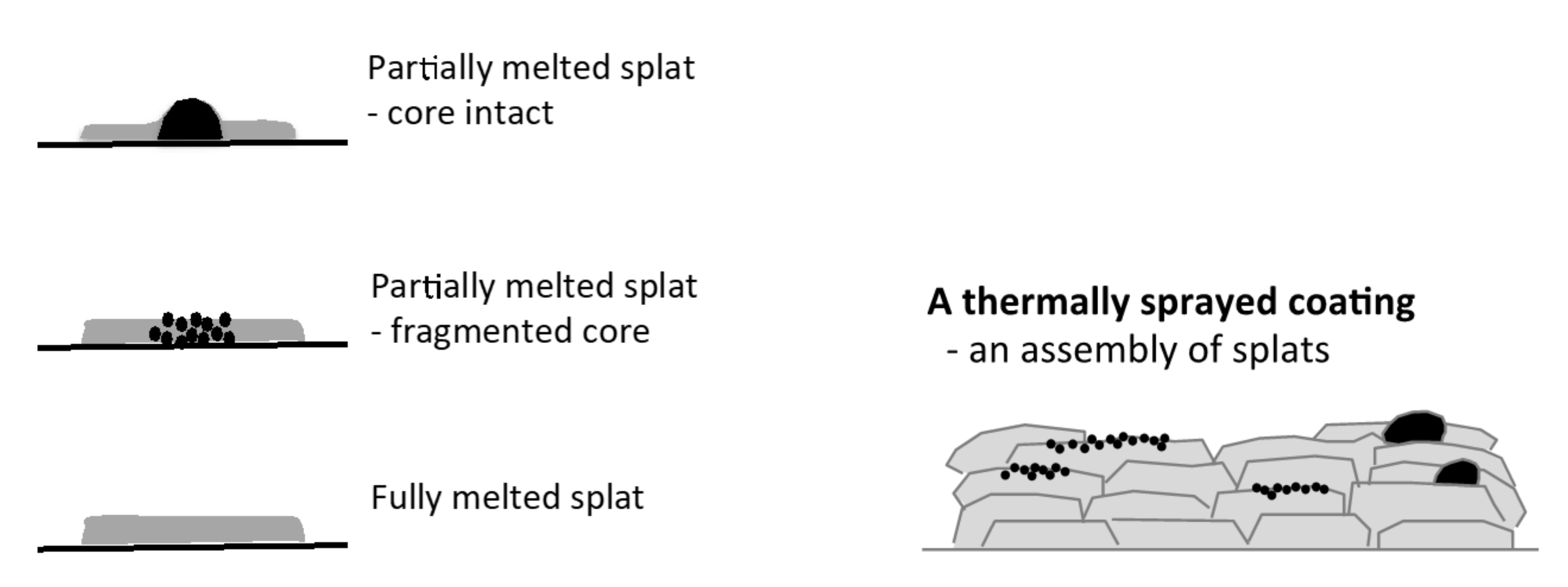
1. Introduction
2. Materials and Methods
2.1. Coating Preparation
2.2. Measurement of Purity, Phase Composition and Surface Electrical Potential
2.3. Measurement of Micro- and Nano-Topography
2.4. Statistics
3. Results
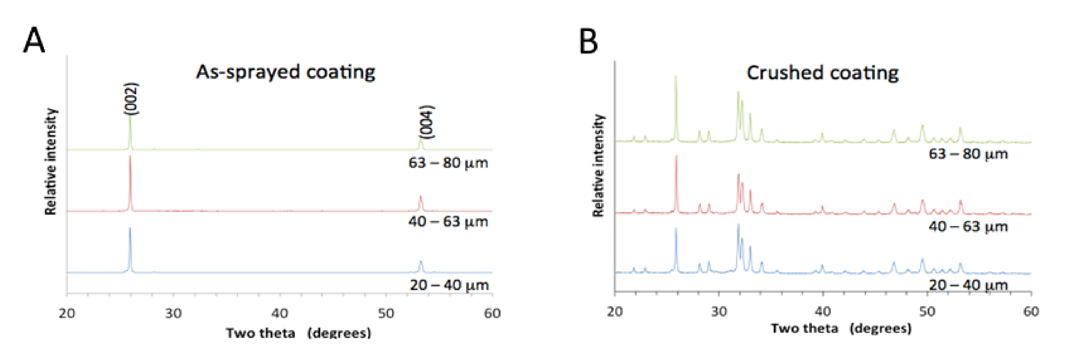
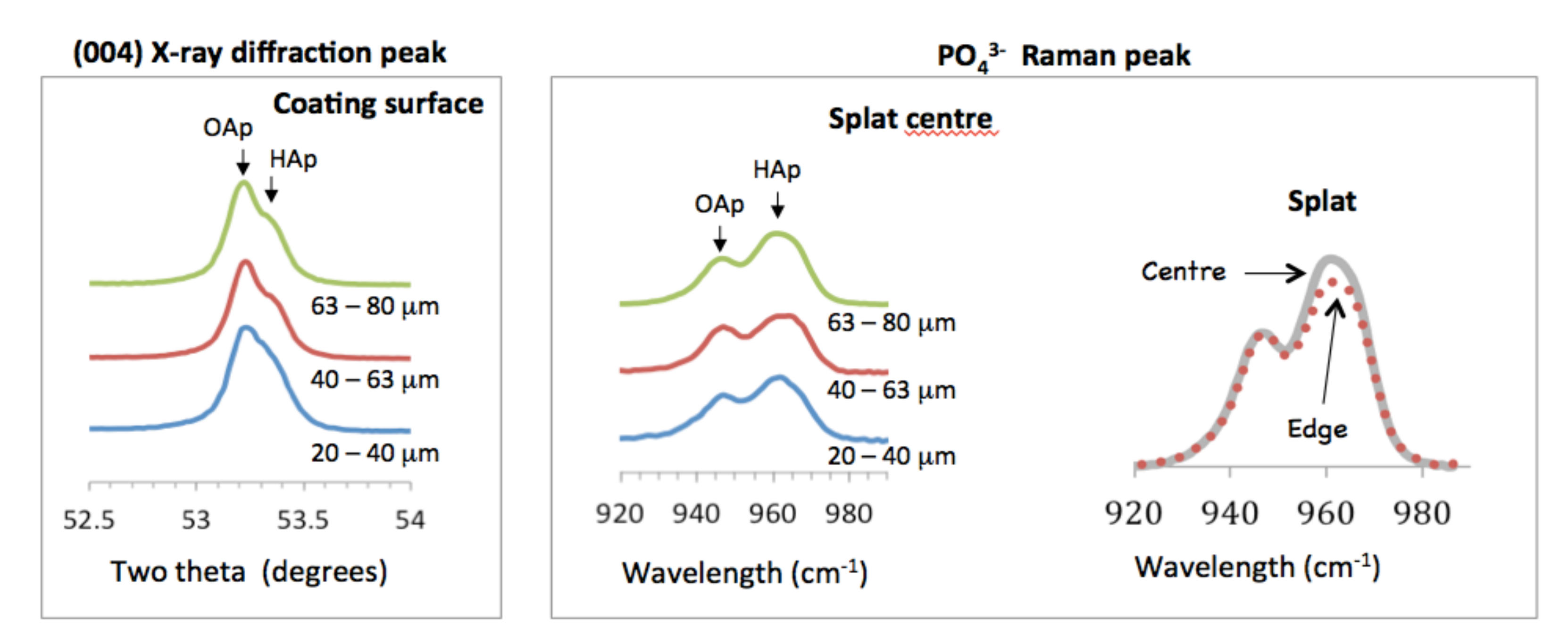
3.1. Purity and Phase Analysis

3.2. Electrical Surface Potential
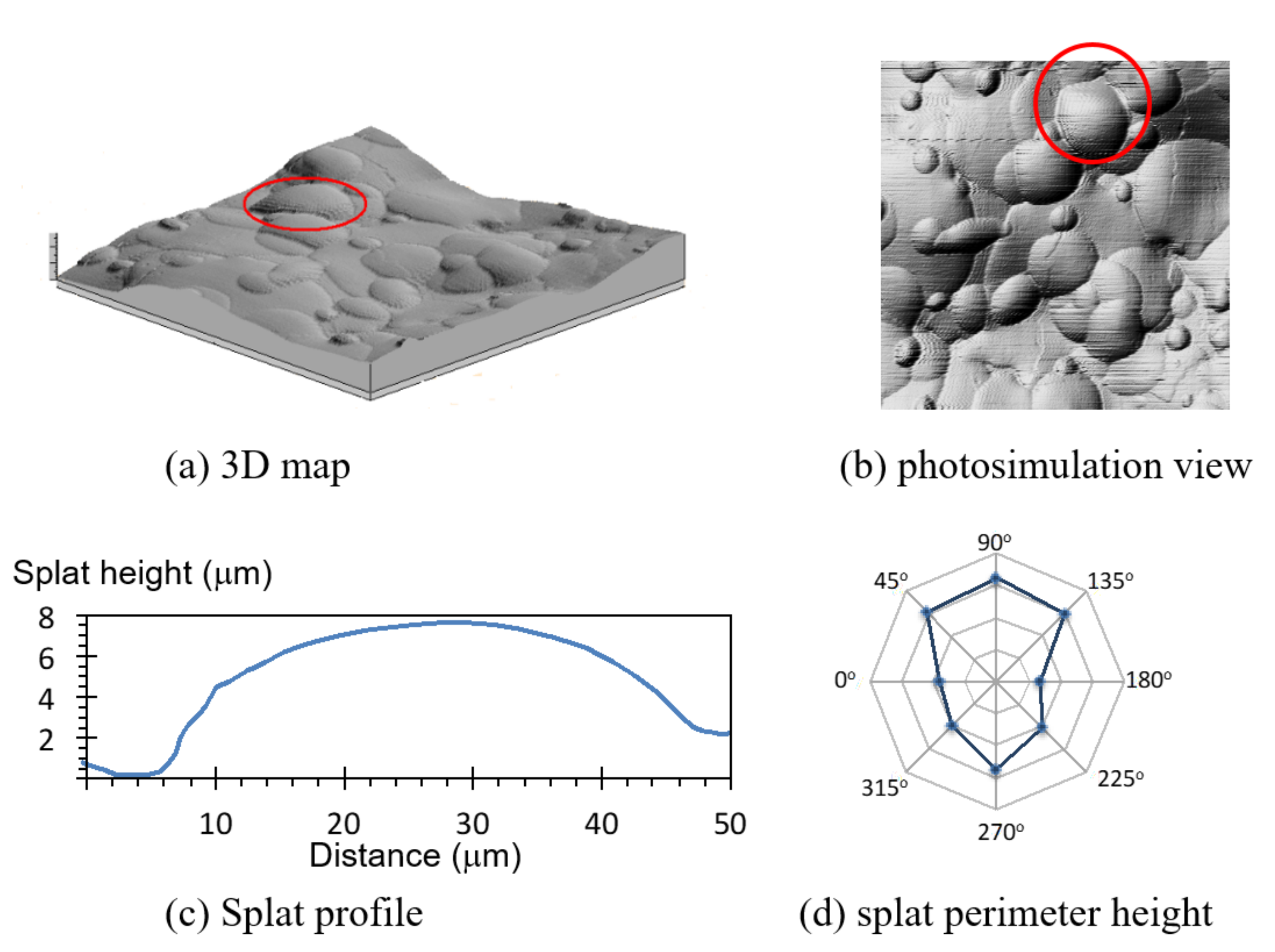
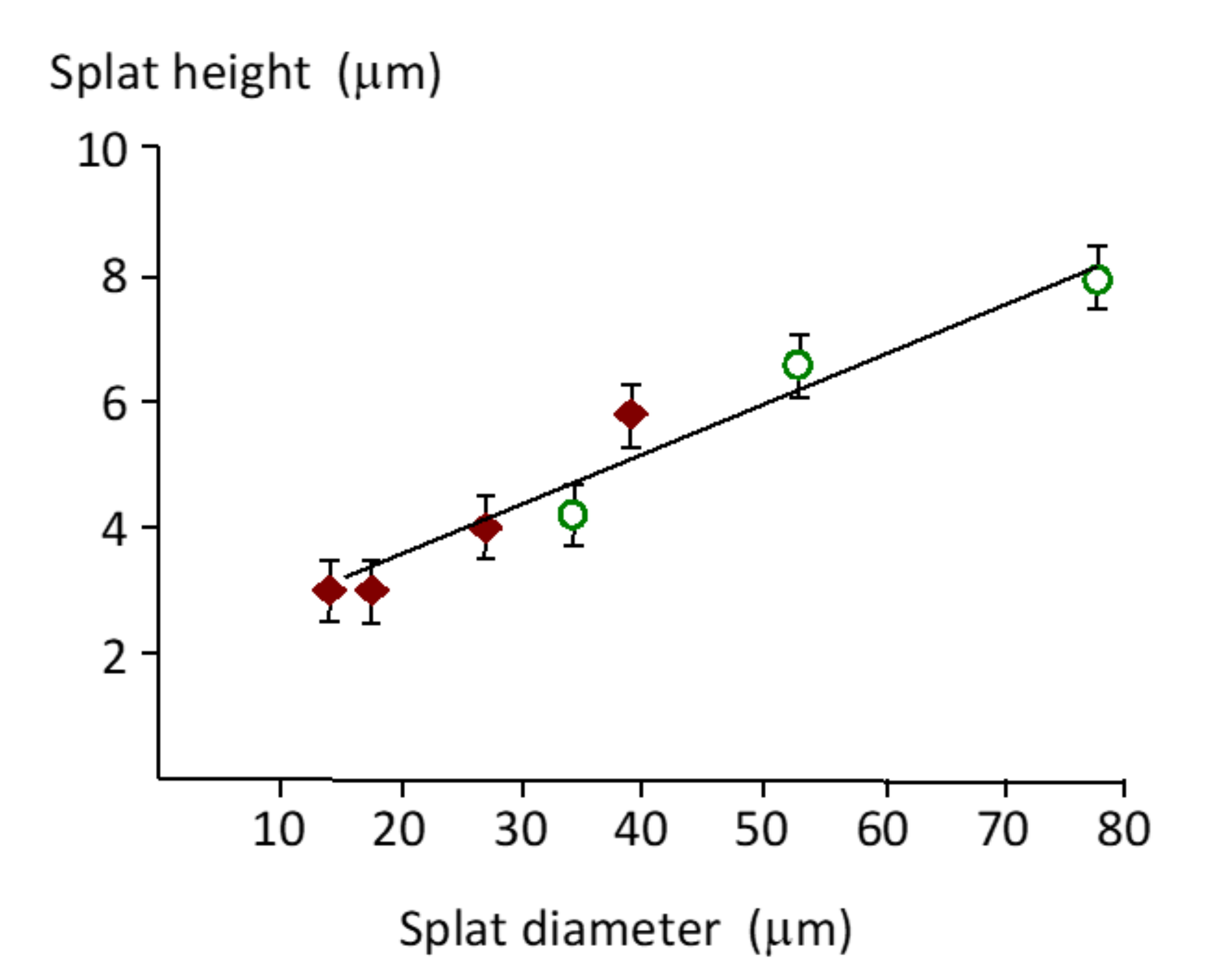
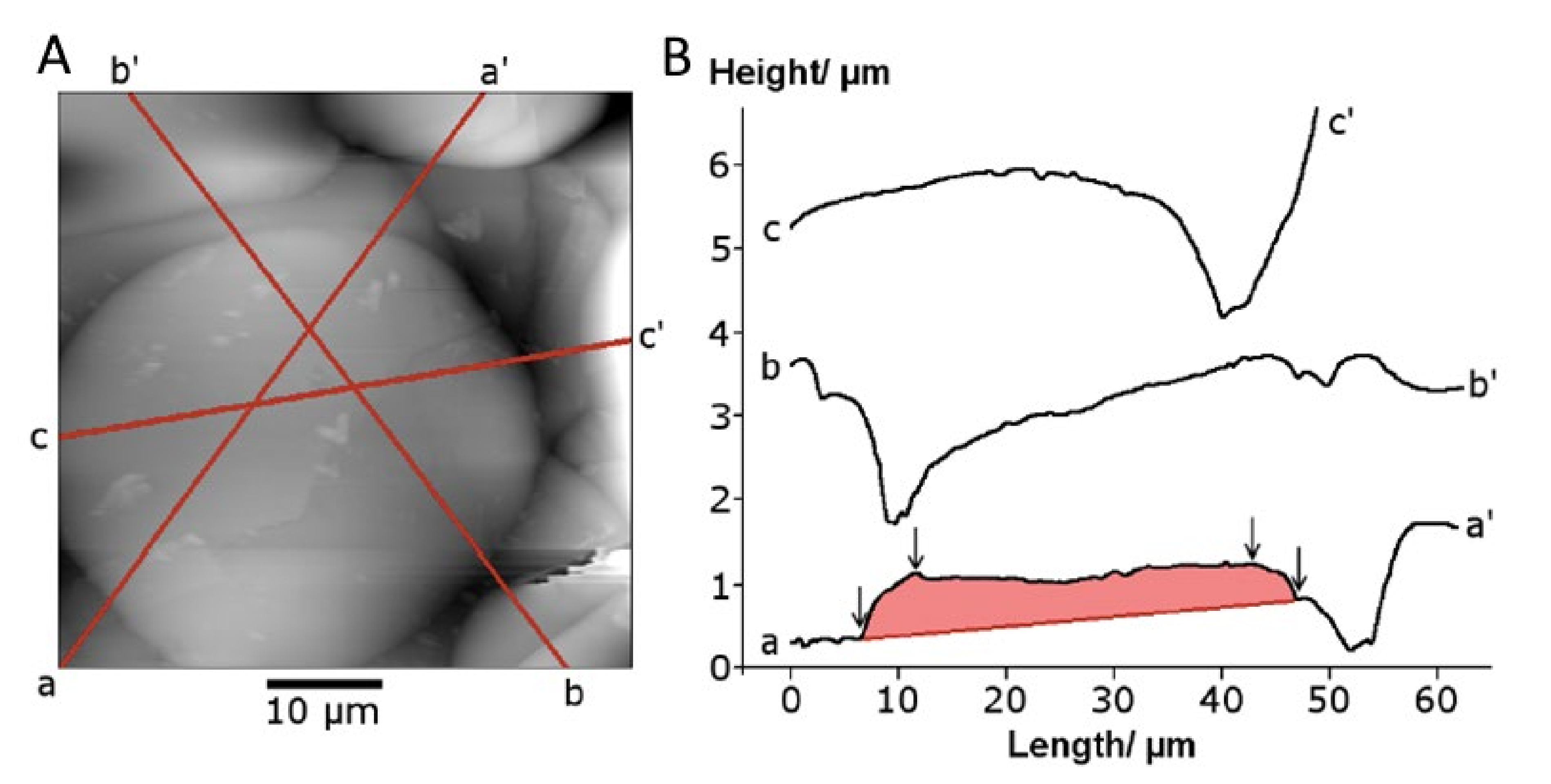
3.3. Splat Topography—Height, Edge Geometry and Flatness

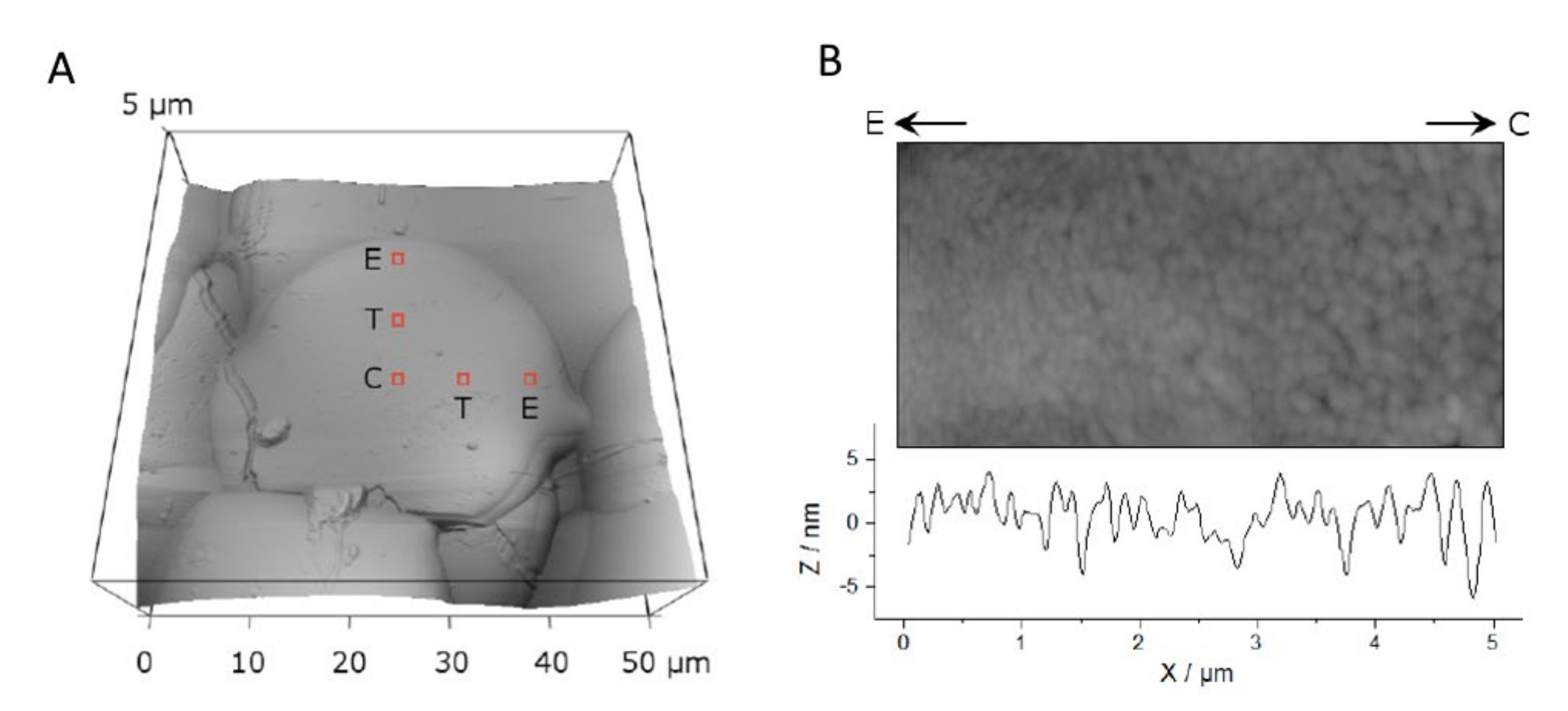
3.4. Crystal Size

| Particle Size (µm) | N | Crystal Size (nm) | IQR | P < 0.05 |
|---|---|---|---|---|
| 20–40 | 27 | 200 | 0.038 | 40–60, 60–80 |
| Edge, E | 10 | 100 | 0.012 | C, T |
| Transition, T | 11 | 215 | 0.020 | E |
| Center, C | 6 | 225 | 0.016 | E |
| 40–60 | 33 | 240 | 0.032 | 20–40 |
| 60–80 | 19 | 260 | 0.063 | 20–40 |

4. Discussion
4.1. Topography of Hydroxyapatite Splats
4.2. Variations in Chemistry on the Coating Surface
4.3. Surface Electrical Potential
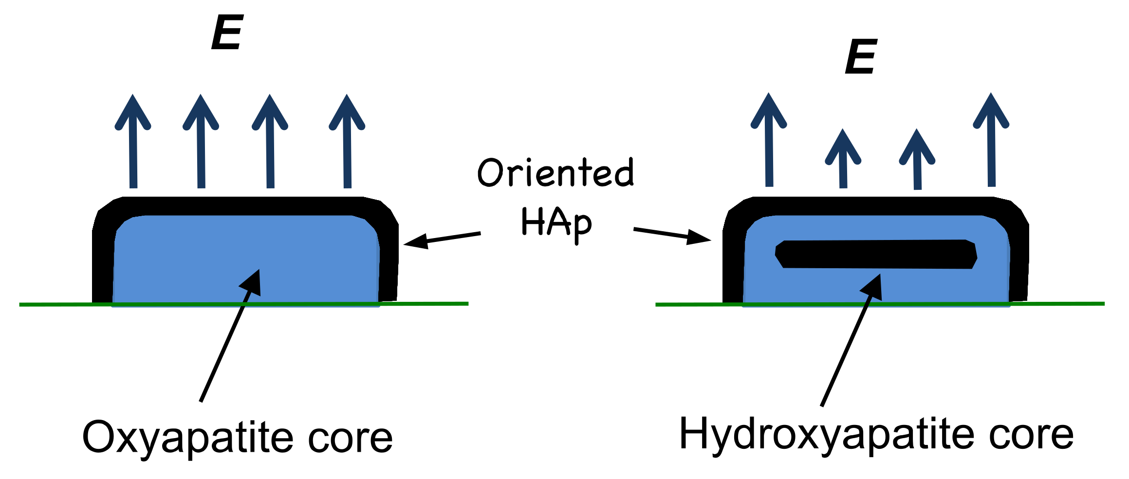
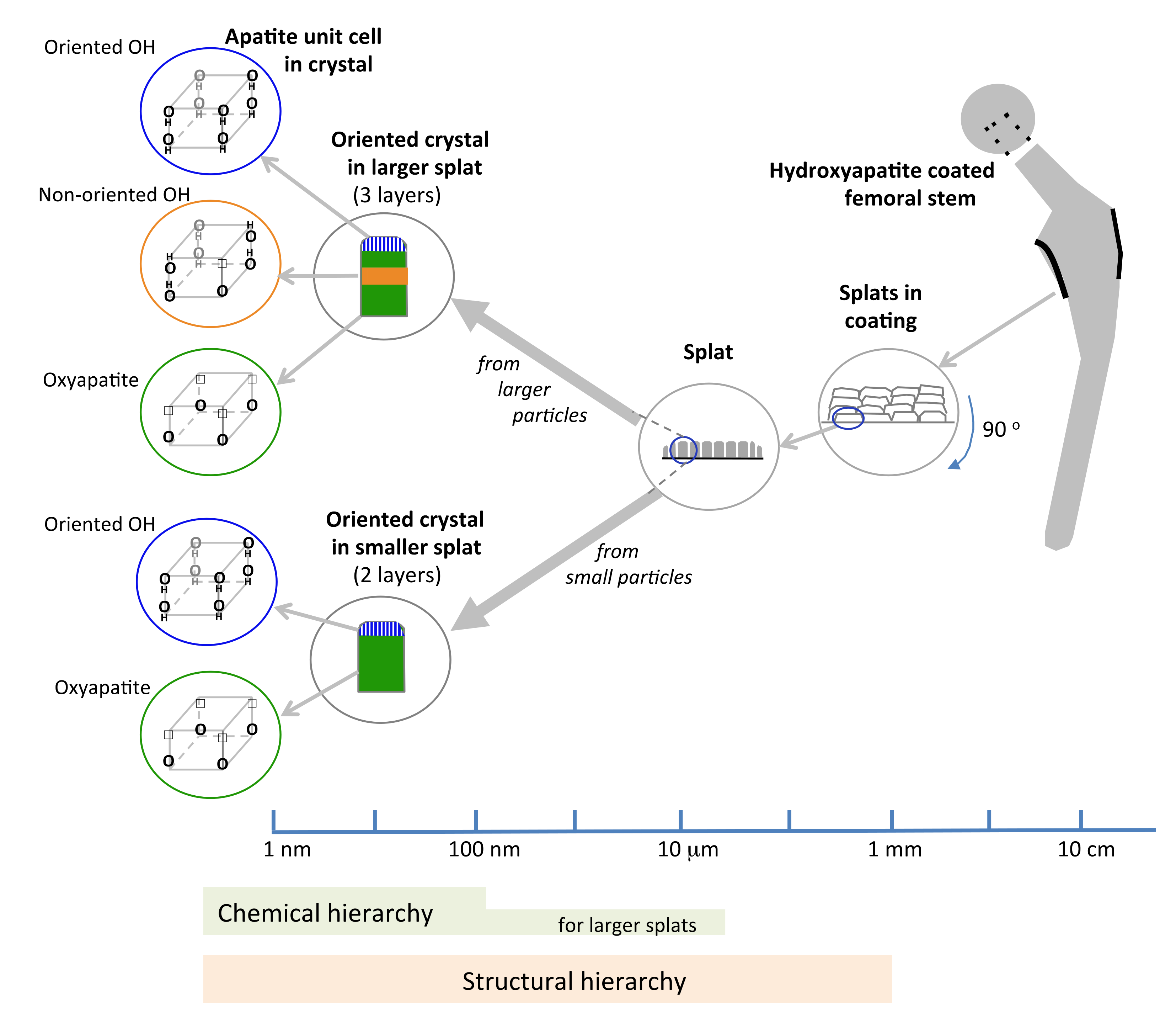
4.4. Structural and Chemical Hierarchy
4.5. Design Opportunities for Hydroxyapatite Implants
5. Conclusions
Author Contributions
Funding
Acknowledgments
Conflicts of Interest
References
- Li, D.; Zheng, Q.; Wang, Y.W.; Chen, H. Combining surface topography with polymer chemistry: Exploring new interfacial biological phenomena. Polym. Chem. 2014, 5, 14–24. [Google Scholar] [CrossRef]
- Ponche, A.; Bigarelle, M.; Anselme, K. Relative influence of surface topography and surface chemistry on cell response to bone implant materials. Part 1: Physico-chemical effects. P. I. Mech. Eng. H. 2010, 224, 1471–1486. [Google Scholar] [CrossRef] [PubMed]
- Rahmati, M.; Silva, E.A.; Reseland, J.E.; Heyward, C.A.; Haugen, H.J. Biological responses to physicochemical properties of biomaterial surface. Chem. Soc. Rev. 2020, 49, 5178–5224. [Google Scholar] [CrossRef] [PubMed]
- Taxt-Lamolle, S.F.; Rubert, M.; Haugen, H.J.; Lyngstadaas, S.P.; Ellingsen, J.E.; Monjo, M. Controlled electro-implementation of fluoride in titanium implant surfaces enhances cortical bone formation and mineralization. Acta Biomater. 2010, 6, 1025–1032. [Google Scholar] [CrossRef] [PubMed]
- Reczyńska, K.; Wrona, M.; Tiainen, H.; Haugen, H.; Pamuła, E. The influence of sintering conditions on microstructure and mechanical properties of titanium dioxide scaffolds for the treatment of bone tissue defects. Acta Bioeng. Biomech. 2015, 17, 3–9. [Google Scholar]
- Thevenot, P.; Hu, W.J.; Tang, L.P. Surface chemistry influences implant biocompatibility. Curr. Top. Med. Chem. 2008, 8, 270–280. [Google Scholar]
- Lu, T.; Qiao, Y.Q.; Liu, X.Y. Surface modification of biomaterials using plasma immersion ion implantation and deposition. Interface Focus 2012, 2, 325–336. [Google Scholar] [CrossRef]
- Frank, M.J.; Walter, M.S.; Tiainen, H.; Rubert, M.; Monjo, M.; Lyngstadaas, S.P.; Haugen, H.J. Coating of metal implant materials with strontium. J. Mater. Sci. Mater. 2013, 24, 2537–2548. [Google Scholar] [CrossRef]
- Hallab, N.J.; Bundy, K.J.; O’Connor, K.; Clark, R.; Moses, R.L. Cell adhesion to biomaterials: Correlations between surface charge, surface roughness, adsorbed protein, and cell morphology. J. Long. Term. Eff. Med. 1995, 5, 209–213. [Google Scholar]
- Kobayashi, T.; Nakamura, S.; Yamashita, K. Enhanced osteobonding by negative surface charges of electrically polarized hydroxyapatite. J. Biomed. Mater. Res. 2001, 57, 477–484. [Google Scholar] [CrossRef]
- Ehrenfest, D.M.D.; Coelho, P.G.; Kang, B.S.; Sul, Y.T.; Albrektsson, T. Classification of osseointegration implant surfaces: Materials, chemistry and topography. Trends. Biotechnol. 2010, 28, 198–206. [Google Scholar] [CrossRef] [PubMed]
- Frank, M.J.; Walter, M.S.; Bucko, M.M.; Pamula, E.; Lyngstadaas, S.P.; Haugen, H.J. Polarization of modified titanium and titanium-zirconium creates nano-structures while hydride formation is modulated. Appl. Surf. Sci. 2013, 282, 7–16. [Google Scholar] [CrossRef]
- Frank, M.J.; Walter, M.S.; Lyngstadaas, S.P.; Wintermantel, E.; Haugen, H.J. Hydrogen content in titanium and a titanium-zirconium alloy after acid etching. Mat. Sci. Eng. C Mater. 2013, 33, 1282–1288. [Google Scholar] [CrossRef] [PubMed]
- Dumbleton, J.; Manley, M.T. Current concepts review - Hydroxyapatite-coated prostheses in total hip and knee arthroplasty. J. Bone Joint Surg. 2004, 86, 2526–2540. [Google Scholar] [CrossRef] [PubMed]
- Prevey, P.S. X-ray diffraction characteriztion of crystallinity and phase composition in plasma-sprayed hydroxyapatite coatings. J. Therm. Spray Technol. 2000, 9, 369–376. [Google Scholar] [CrossRef]
- Gross, K.A.; Berndt, C.C.; Herman, H. Amorphous phase formation in plasma-sprayed hydroxyapatite coatings. J. Biomed. Mater. Res. 1998, 39, 407–414. [Google Scholar] [CrossRef]
- Gross, K.A.; Muller, D.; Lucas, H.; Haynes, D.R. Osteoclast resorption of thermal spray hydroxyapatite coatings is influence by surface topography. Acta Biomat. 2012, 8, 1948–1956. [Google Scholar] [CrossRef]
- Salimijazi, H.R.; Pershin, L.; Coyle, T.W.; Mostaghimi, J.; Chandra, S.; Lau, Y.C.; Rosenzweig, L.; Moran, E. Effect of droplet characteristics and substrate surface topography on the final morphology of plasma-sprayed zirconia single splats. J. Therm. Spray Technol. 2007, 16, 291–299. [Google Scholar] [CrossRef]
- Cizek, J.; Khor, K.A. Role of in-flight temperature and velocity of powder particles on plasma sprayed hydroxyapatite coating characteristics. Surf. Coat. Technol. 2012, 206, 2181–2191. [Google Scholar] [CrossRef]
- Vardelle, M.; Vardelle, A.; Leger, A.C.; Fauchais, P.; Gobin, D. Influence of particle parameters at impact on splat formation and solidification in plasma spraying processes. J. Therm. Spray Technol. 1995, 4, 50–58. [Google Scholar] [CrossRef]
- Schade, M.; Varlamova, O.; Reif, J.; Blumtritt, H.; Erfurth, W.; Leipner, H.S. High-resolution investigations of ripple structures formed by femtosecond laser irradiation of silicon. Anal. Bioanal Chem. 2010, 396, 1905–1911. [Google Scholar] [CrossRef] [PubMed]
- Garskaite, E.; Gross, K.A.; Yang, S.W.; Yang, T.C.K.; Yang, J.C.; Kareiva, A. Effect of processing conditions on the crystallinity and structure of carbonated calcium hydroxyapatite (CHAp). Cryst. Eng. Comm. 2014, 16, 3950–3959. [Google Scholar] [CrossRef]
- Raynaud, S.; Champion, E.; Bernache-Assollant, D.; Laval, J.P. Determination of calcium/phosphorus atomic ratio of calcium phosphate apatites using X-ray diffractometry. J. Am. Ceram. Soc. 2001, 84, 359–366. [Google Scholar] [CrossRef]
- Gross, K.A.; Berndt, C.C.; Dinnebier, R.; Stephens, P. Oxyapatite in hydroxyapatite coatings. J. Mater. Sci. 1998, 33, 3985–3991. [Google Scholar] [CrossRef]
- Demnati, I.; Parco, M.; Grossin, D.; Fagoaga, I.; Drouet, C.; Barykin, G.; Combes, C.; Braceras, I.; Goncalves, S.; Rey, C. Hydroxyapatite coating on titanium by a low energy plasma spraying mini-gun. Surf. Coat. Technol. 2012, 206, 2346–2353. [Google Scholar] [CrossRef]
- Bianchi, L.; Denoirjean, A.; Blein, F.; Fauchais, P. Microstructural investigation of plasma-sprayed ceramic splats. Thin Solid Films 1997, 299, 125–135. [Google Scholar] [CrossRef]
- Montanaro, L.; Arciola, C.R.; Campoccia, D.; Cervellati, M. In vitro effects on MG63 osteoblast-like cells following contact with two roughness-differing fluorohydroxyapatite-coated titanium alloys. Biomaterials 2002, 23, 3651–3659. [Google Scholar] [CrossRef]
- Hahn, B.D.; Park, D.S.; Choi, J.J.; Ryu, J.; Yon, W.H.; Choi, J.H.; Kim, J.W.; Cho, Y.L.; Park, C.; Kim, H.E.; et al. Preparation and in vitro characterization of aerosol-deposited hydroxyapatite coatings with different surface roughnesses. Appl. Surf. Sci. 2011, 257, 7792–7799. [Google Scholar] [CrossRef]
- Fauchais, P.; Fukumoto, M.; Vardelle, A.; Vardelle, M. Knowledge concerning splat formation: An invited review. J. Therm. Spray Technol. 2004, 13, 337–360. [Google Scholar] [CrossRef]
- Dhiman, R.; McDonald, A.G.; Chandra, S. Predicting splat morphology in a thermal spray process. Surf. Coat. Technol. 2007, 201, 7789–7801. [Google Scholar] [CrossRef]
- Pasandideh-Fard, M.; Pershin, V.; Chandra, S.; Mostaghimi, J. Splat shapes in a thermal spray coating process: Simulations and experiments. J. Therm. Spray Technol. 2002, 11, 206–217. [Google Scholar] [CrossRef]
- Fukumoto, M.; Yamaguchi, T.; Yamada, M.; Yasui, T. Splash splat to disk splat transition in plasma-sprayed metallic materials. J. Therm. Spray Technol. 2007, 16, 905–912. [Google Scholar] [CrossRef]
- Gross, K.A.; Young, C.J.; Beck, M.A.; Keebaugh, E.W.; Bronts, T.J.; Saber-Samandari, S.; Riley, D.P. Characterisation and dissolution of functionalised amorphous calcium phosphate biolayers using single splat technology. Acta Biomat. 2011, 77, 2270–2275. [Google Scholar] [CrossRef] [PubMed]
- Saber-Samandari, S.; Gross, K.A. Nanoindentation on the surface of thermally sprayed coatings. Surf. Coat. Technol. 2009, 203, 3516–3520. [Google Scholar] [CrossRef]
- Xu, R.M.; Fleming, P.D.; Pekarovicova, A.; Bliznyuk, V. The effect of ink jet paper roughness on print gloss. J. Imag. Sci. Techn. 2005, 49, 660–666. [Google Scholar] [CrossRef]
- Saber-Samandari, S.; Alamara, K.; Saber-Samandari, S. Calcium phosphate coatings: Morphology, micro-structure and mechanical properties. Ceram. Internat. 2014, 40, 563–572. [Google Scholar] [CrossRef]
- Carayon, M.T.; Lacout, J.L.S. Study of the Ca/P atomic ratio of the amorphous phase in plasma-sprayed hydroxyapatite coatings. J. Solid State Chem. 2003, 172, 339–350. [Google Scholar] [CrossRef]
- Dai, L.; Yang, G.X.; Zhou, H.Z.; He, Z.X.; Li, Y.H.; Wang, L. Mixed potential NH3 sensor based on Mg-doped lanthanum silicate oxyapatite. Sensor Actuat. B Chem. 2016, 224, 356–363. [Google Scholar] [CrossRef]
- Elliott, J.C. Structure and Chemistry of the Apatites and Other Calcium Orthophosphates; Elsevier: Amsterdam, The Netherlands, 2013. [Google Scholar]
- Drukteinis, S.E. Engineering of Pulsed Laser Deposited Calcium Phosphate Biomaterials in Controlled Atmospheres. Ph.D. Thesis, University of Alabama at Birmingham, Birmingham, AL, USA, 2012. [Google Scholar]
- Ito, S.; Nakamura, S.; Kobayashi, T.; Shinomiya, K.; Yamashita, K. Effect of electrical polarization of hydroxyapatite ceramics on new bone formation. Calc. Tissue. Int. 2006, 78, 133–142. [Google Scholar] [CrossRef]
- Sampath, S.; Jiang, X.Y.; Matejicek, J.; Leger, A.C.; Vardelle, A. Substrate temperature effects on splat formation, microstructure development and properties of plasma sprayed coatings Part I: Case study for partially stabilized zirconia. Mat. Sci. Eng. A Struct. 1999, 272, 181–188. [Google Scholar] [CrossRef]
- Li, H.; Khor, K.A.; Cheang, P. Effect of steam treatment during plasma spraying on the microstructure of hydroxyapatite splats and coatings. J. Therm. Spray Technol. 2006, 15, 610–616. [Google Scholar] [CrossRef]
- Dugas, V.; Chevalier, Y. Surface hydroxylation and silane grafting on fumed and thermal silica. J. Colloid Interf. Sci. 2003, 264, 354–361. [Google Scholar] [CrossRef]
- Tanaka, H.; Chikazawa, M.; Kandori, K.; Ishikawa, T. Influence of thermal treatment on the structure of calcium hydroxyapatite. Phys. Chem. Chem. Phys. 2000, 2, 2647–2650. [Google Scholar] [CrossRef]
- Zhou, C.C.; Ye, X.J.; Fan, Y.J.; Ma, L.; Tan, Y.F.; Qing, F.Z.; Zhang, X.D. Biomimetic fabrication of a three-level hierarchical calcium phosphate/collagen/hydroxyapatite scaffold for bone tissue engineering. Biofabrication 2014, 6, 035013. [Google Scholar] [CrossRef]
- Xiao, Y.Q.; Ren, E.Z.; Hu, M.Y.; Liu, K. Effect of Particle In-Flight Behavior on the Microstructure and Fracture Toughness of YSZ TBCs Prepared by Plasma Spraying. Coatings 2018, 8, 309. [Google Scholar] [CrossRef]
- Gross, K.A.; Ray, N.; Rokkum, M. The contribution of coating microstructure to degradation and particle release in hydroxyapatite coating prostheses. J. Biomed. Mater. Res. 2002, 63, 106–114. [Google Scholar] [CrossRef]
- Velard, F.; Laurent-Maquin, D.; Guillaume, C.; Bouthors, S.; Jallot, E.; Nedelec, J.M.; Belaaouaj, A.; Laquirriere, P. Polymorphonuclear neutrophil response to hydroxyapatite particles, implication in acute inflammatory reaction. Acta Biomater. 2009, 5, 1708–1715. [Google Scholar] [CrossRef]
- Rahbek, O. The Influence of Hydroxyapatite Coating on the Peri-implant Migration of Polyethylene Particles. Ph.D. Thesis, Faculty of Health Sciences, University of Aarhus, Aarhus, Denmark, 2002. [Google Scholar]
- Rokkum, M.; Brandt, M.; Bye, K.; Hetland, K.R.; Waage, S.; Reigstad, A. Polyethylene wear, osteolysis and acetabular loosening with an HA coated hip prostheseis. A follow-up of 94 consecutive arthoplasties. J. Bone Jt. Surg. 1999, 81, 582–589. [Google Scholar] [CrossRef]
- Zhu, H.G.; Ji, J.; Tan, O.G.; Barbosa, M.A.; Shen, J.C. Surface engineering og poly (DL-lactide) via electrostratic self-assembly of extracellular matrix-like molecules. Biomacromolecules 2003, 4, 378–386. [Google Scholar] [CrossRef]
- Ohgaki, M.; Kizuki, T.; Katsura, M.; Yamashita, K. Manipulation of selective cell adhesion and growth by surface charges of electrically polarized hydroxyapatite. J. Biomed. Mater. Res. 2001, 57, 366–373. [Google Scholar] [CrossRef]
- Lee, W.H.; Loo, C.Y.; Van, K.L.; Zavgorodniy, A.V.; Rohanizadeh, R. Modulating protein adsorption onto hydroxyapatite particles using different amino acis treatments. J. R. Soc. Interface 2012, 9, 918–927. [Google Scholar] [CrossRef] [PubMed]


© 2020 by the authors. Licensee MDPI, Basel, Switzerland. This article is an open access article distributed under the terms and conditions of the Creative Commons Attribution (CC BY) license (http://creativecommons.org/licenses/by/4.0/).
Share and Cite
Gross, K.A.; Petzold, C.; Pluduma-LaFarge, L.; Kumermanis, M.; Haugen, H.J. Structural and Chemical Hierarchy in Hydroxyapatite Coatings. Materials 2020, 13, 4447. https://doi.org/10.3390/ma13194447
Gross KA, Petzold C, Pluduma-LaFarge L, Kumermanis M, Haugen HJ. Structural and Chemical Hierarchy in Hydroxyapatite Coatings. Materials. 2020; 13(19):4447. https://doi.org/10.3390/ma13194447
Chicago/Turabian StyleGross, Karlis A., Christiane Petzold, Liene Pluduma-LaFarge, Maris Kumermanis, and Håvard J. Haugen. 2020. "Structural and Chemical Hierarchy in Hydroxyapatite Coatings" Materials 13, no. 19: 4447. https://doi.org/10.3390/ma13194447
APA StyleGross, K. A., Petzold, C., Pluduma-LaFarge, L., Kumermanis, M., & Haugen, H. J. (2020). Structural and Chemical Hierarchy in Hydroxyapatite Coatings. Materials, 13(19), 4447. https://doi.org/10.3390/ma13194447