Magnetoelectrics: Three Centuries of Research Heading Towards the 4.0 Industrial Revolution

 ,
,  and
and 
Abstract
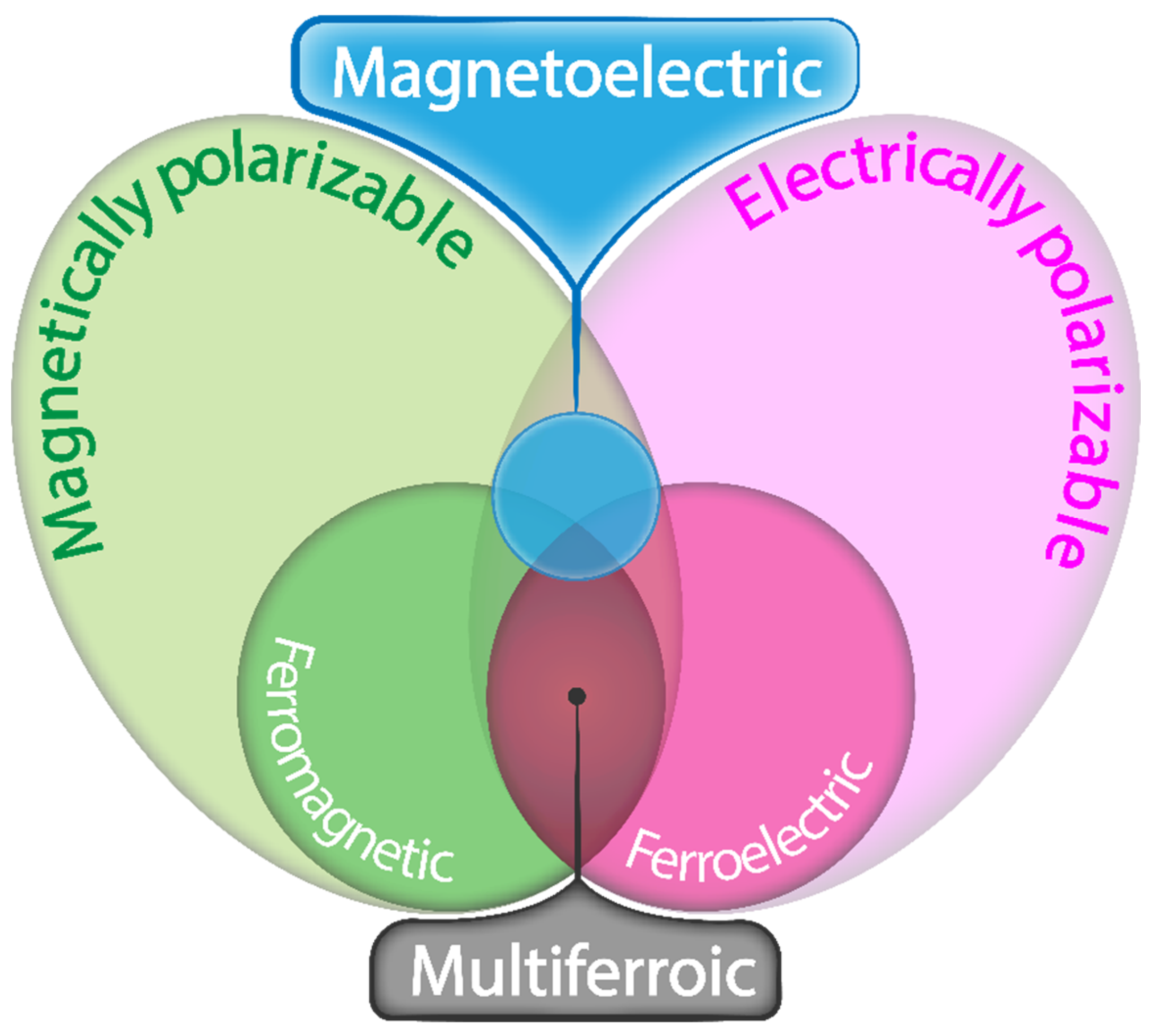
1. Introduction
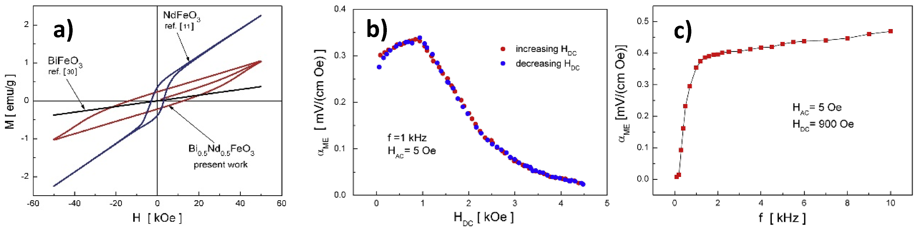
2. Single-Phase ME
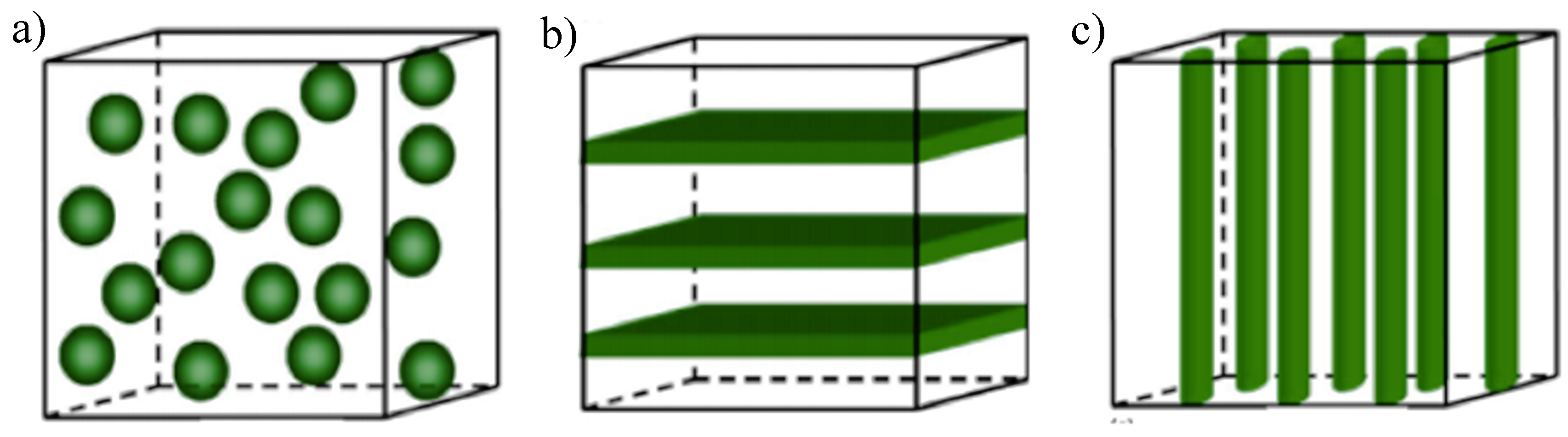
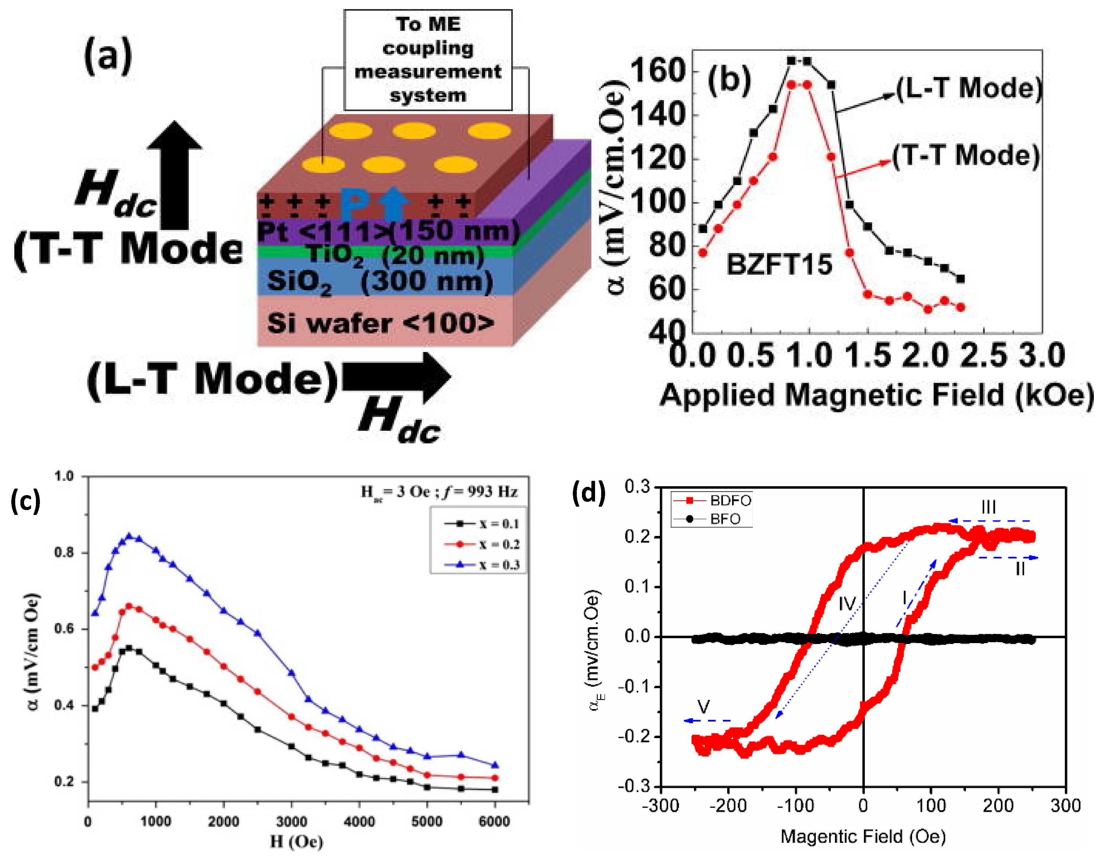
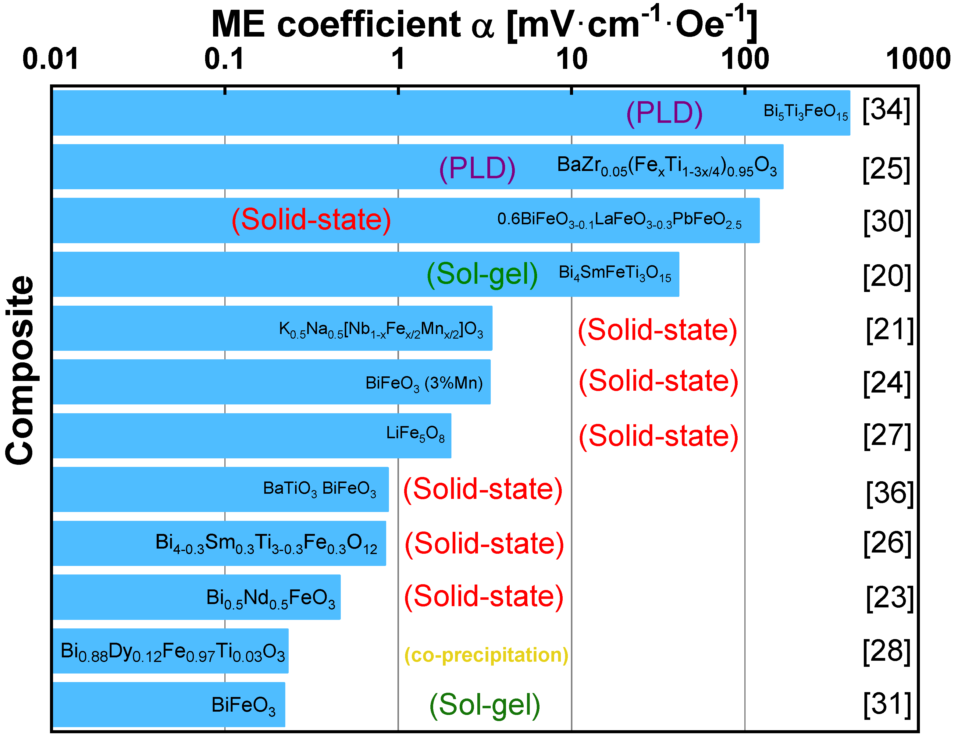
3. Ceramic-Based ME
- selection of the composition (preferably near morphotropic phase boundary (MPB) or polymorphic phase transition (PPT)) and modification by doping;
- microstructure design via domain engineering and texturing [38].
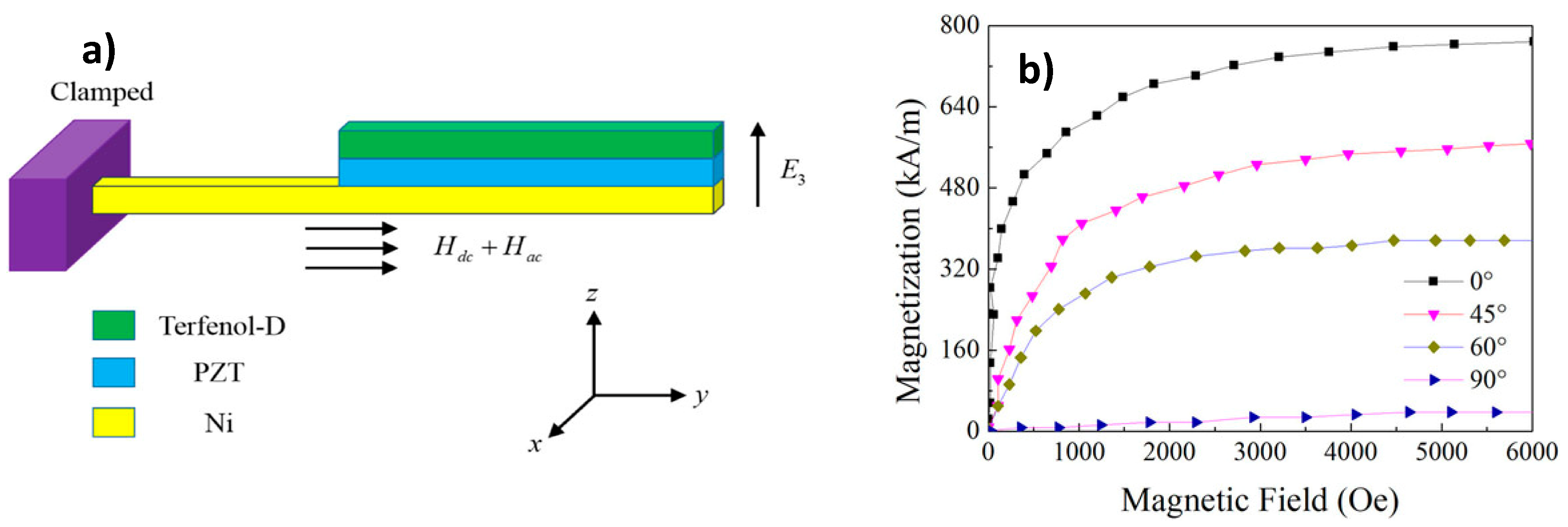
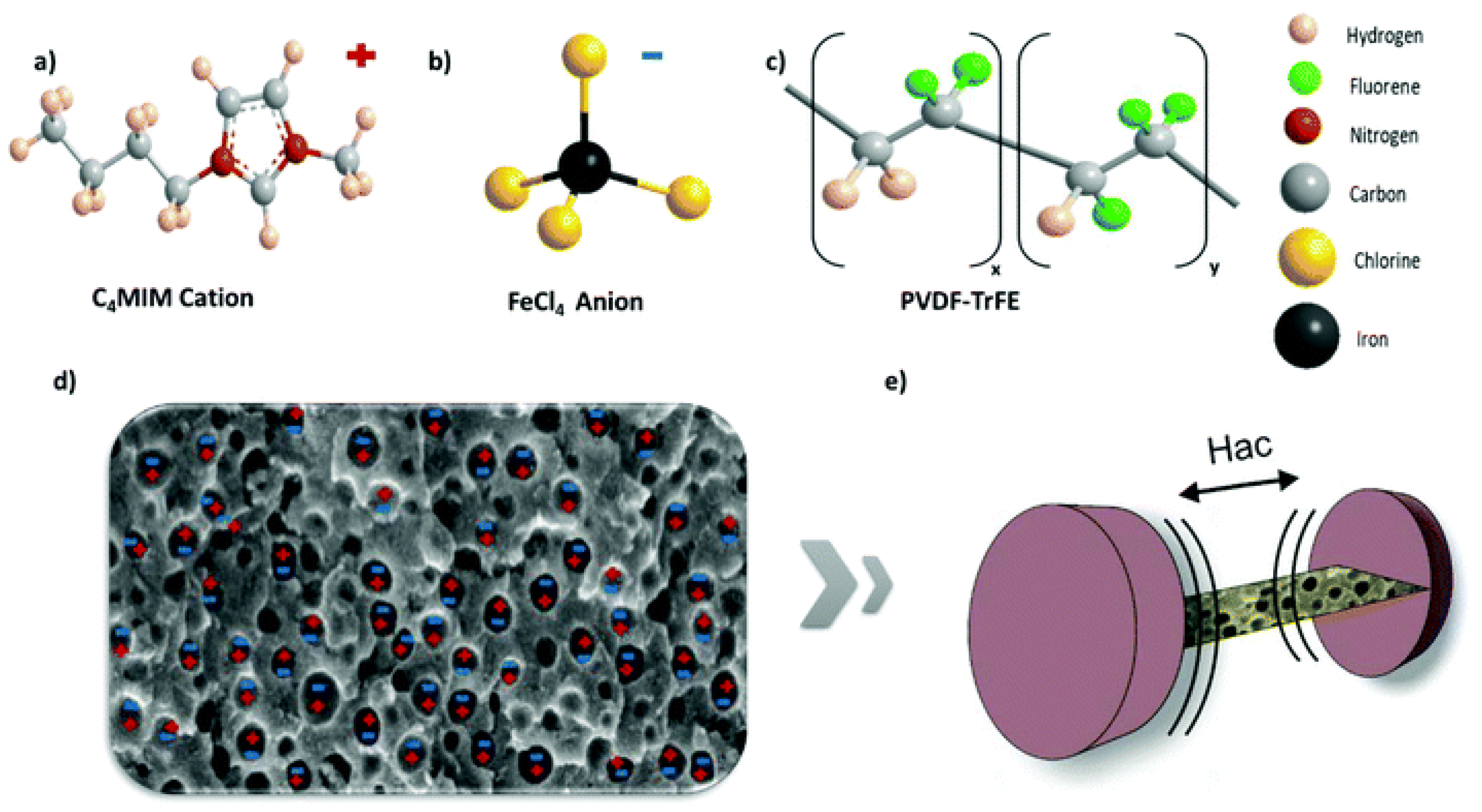
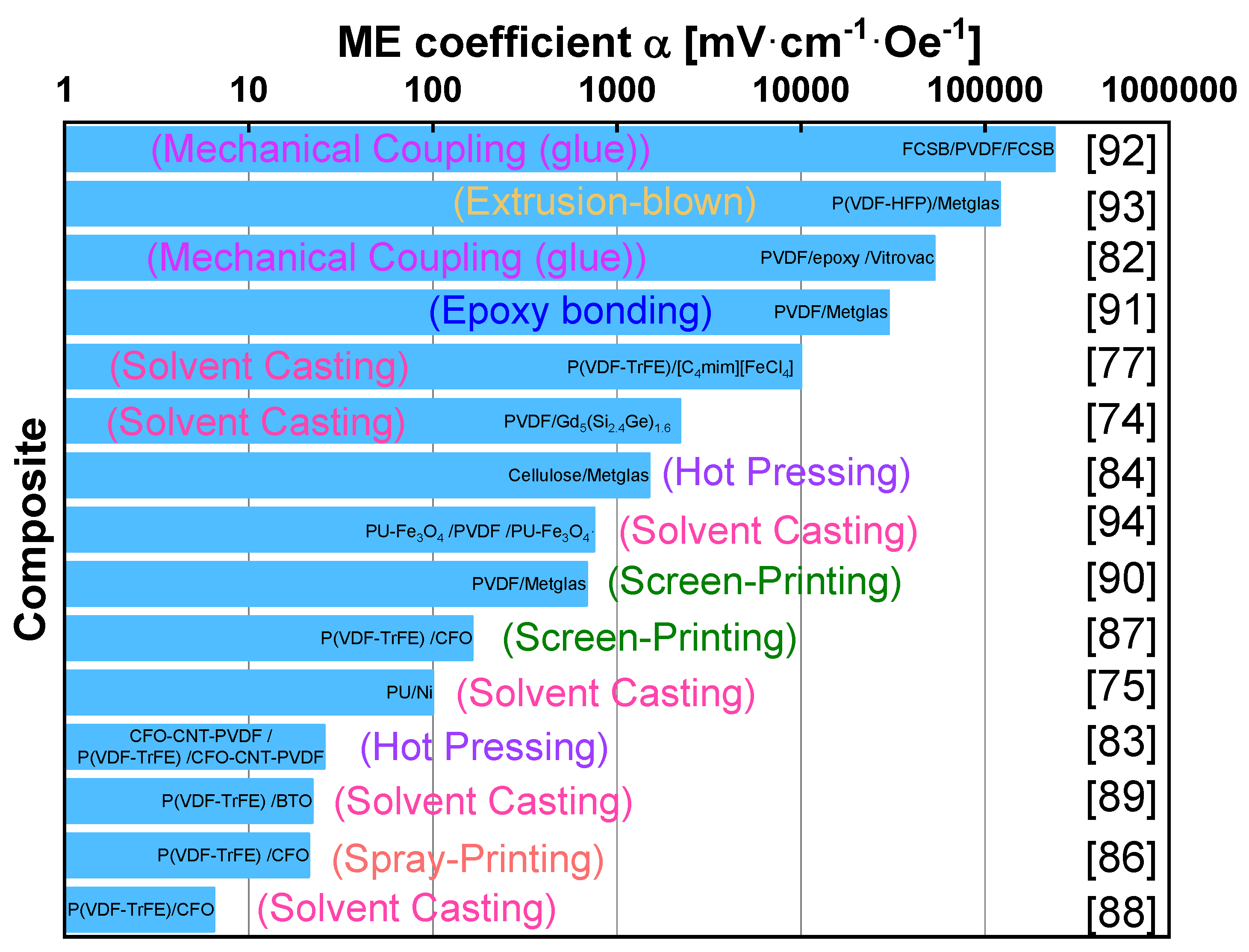
4. Polymer-Based Magnetoelectrics
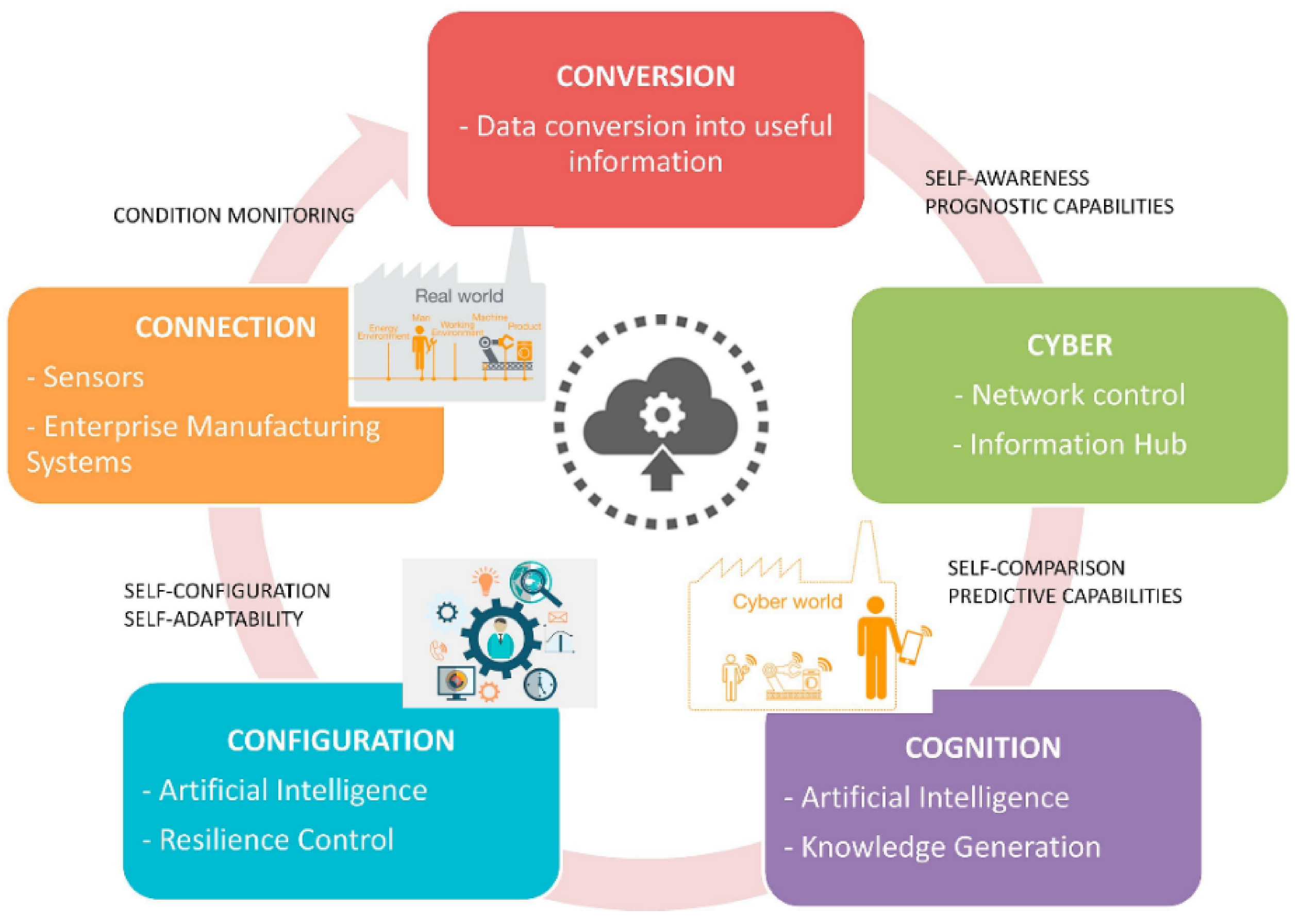
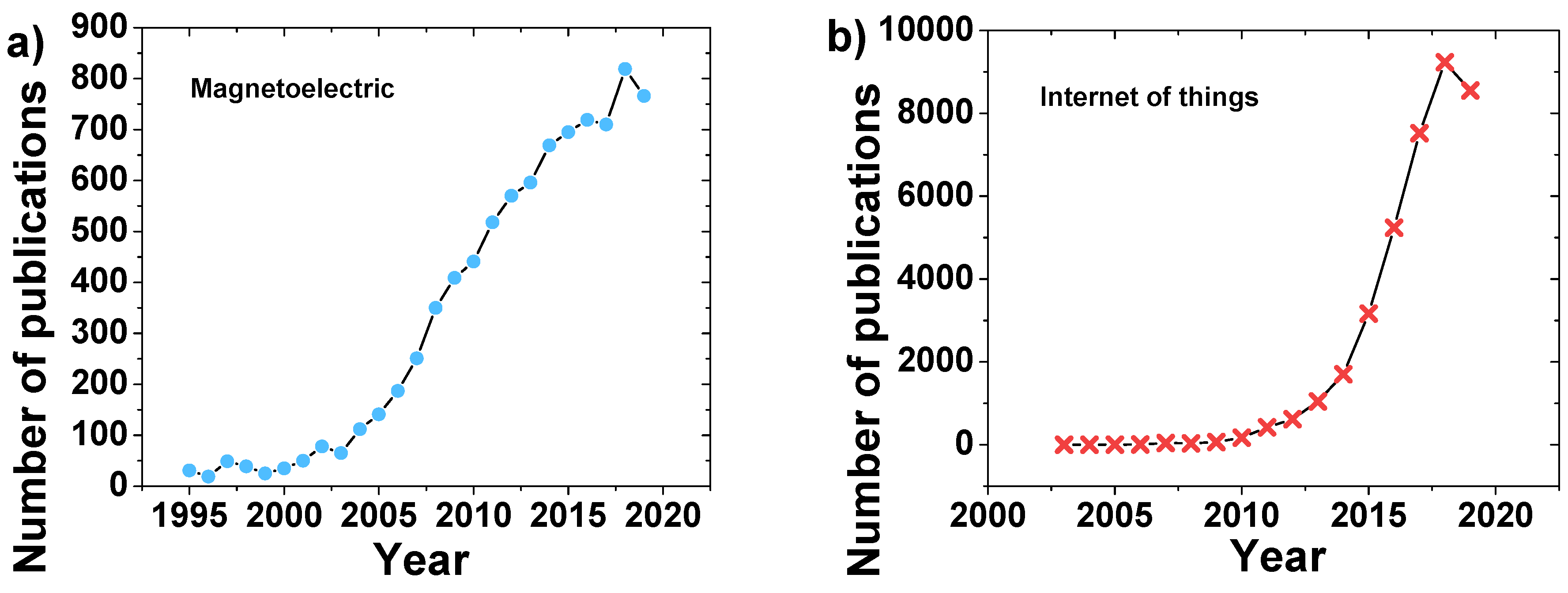
5. Applications in the 4.0 Context
6. Challenges and Future Perspectives
Author Contributions
Funding
Acknowledgments
Conflicts of Interest
References
- Eerenstein, W.; Mathur, N.D.; Scott, J.F. Multiferroic and magnetoelectric materials. Nature 2006, 442, 759–765. [Google Scholar] [CrossRef]
- Nan, C.-W.; Bichurin, M.; Dong, S.; Viehland, D.; Srinivasan, G. Multiferroic magnetoelectric composites: Historical perspective, status, and future directions. J. Appl. Phys. 2008, 103, 031101. [Google Scholar] [CrossRef]
- Röntgen, W.C. Ueber die durch Bewegung eines im homogenen electrischen Felde befindlichen Dielectricums hervorgerufene electrodynamische Kraft. Ann. Phys. 1888, 271, 264–270. [Google Scholar] [CrossRef]
- Curie, P.J.J.d.P. Sur la symétrie des phénomènes physiques: Symétrie d’un champ électrique et d’un champ magnétique. J. Phys. 1894, 3, 393–415. [Google Scholar]
- Dzyaloshinskii, I.E. On the magneto-electrical effects in antiferromagnets. Soviet Phys. JETP 1960, 10, 628–629. [Google Scholar]
- Wang, K.-F.; Liu, J.-M.; Ren, Z. Multiferroicity: The coupling between magnetic and polarization orders. Adv. Phys. 2009, 58, 321–448. [Google Scholar] [CrossRef]
- Fiebig, M. Revival of the magnetoelectric effect. J. Phys. D Appl. Phys. 2005, 38, R123–R152. [Google Scholar] [CrossRef]
- Van Suchtelen, J. Product properties: A new application of composite materials. Philips Res. Rep. 1972, 2, 28–37. [Google Scholar]
- Lu, C.; Wu, M.; Lin, L.; Liu, J.-M. Single-phase multiferroics: New materials, phenomena, and physics. Natl. Sci. Rev. 2019, 6, 653–668. [Google Scholar] [CrossRef]
- Palneedi, H.; Annapureddy, V.; Priya, S.; Ryu, J. Status and perspectives of multiferroic magnetelectric composite materials and applications. Actuators 2015, 5, 9. [Google Scholar] [CrossRef]
- Fernández, C.L.; Pereira, N.; Martins, P.; Lanceros-Méndez, S. Theoretical design of high-performance polymer-based magnetoelectric of fibrilar structures. Compos. Sci. Technol. 2018, 155, 126–136. [Google Scholar] [CrossRef]
- Tong, C. Introduction to Materials for Advanced Energy Systems; Springer: Berlin, Germany, 2019. [Google Scholar]
- Shi, Z.; Zhang, J.; Li, J.-F.; Nan, C.-W.; Ma, J. Magnetoelectric properties of multiferroic composites with pseudo 1–3 type structure. MRS Proc. 2006, 966, 124108. [Google Scholar] [CrossRef]
- Lanceros-Méndez, S.; Martins, P. Magnetoelectric Polymer-Based Composites: Fundamentals and Applications; John Wiley & Sons: Weinheim, Germany, 2017. [Google Scholar]
- Longo, F.; Nicoletti, L.; Padovano, A. Smart operators in industry 4.0: A human-centered approach to enhance operators’ capabilities and competencies within the new smart factory context. Comput. Ind. Eng. 2017, 113, 144–159. [Google Scholar] [CrossRef]
- Gil, K.; Gil, J.; Cruz, B.; Ramirez, A.; Medina, M.; Torres, J. Experimental set up of a magnetoelectric measuring system operating at different temperatures. In Proceedings of the Journal of Physics: Conference Series, Bucaramanga, Colombia, 4–9 May 2015; IOP Publishing: Bristol, UK, 2016; Volume 687, p. 12090. [Google Scholar]
- Aceto, G.; Persico, V.; Pescapé, A. Industry 4.0 and health: Internet of things, big data, and cloud computing for healthcare 4.0. J. Ind. Inf. Integr. 2020, 18, 100129. [Google Scholar] [CrossRef]
- Dalenogare, L.S.; Benitez, G.B.; Ayala, N.F.; Frank, A.G. The expected contribution of Industry 4.0 technologies for industrial performance. Int. J. Prod. Econ. 2018, 204, 383–394. [Google Scholar] [CrossRef]
- Beier, G.; Ullrich, A.; Niehoff, S.; Reißig, M.; Habich, M. Industry 4.0: How it is defined from a sociotechnical perspective and how much sustainability it includes—A literature review. J. Clean. Prod. 2020, 259, 120856. [Google Scholar] [CrossRef]
- Luo, L.; Sun, L.; Long, Y.; Wang, X.; Li, Q.; Liang, K.; Zhao, J.; Yan, W.; Sun, Q.; Su, J.; et al. Multiferroic properties of aurivillius structure Bi4SmFeTi3O15 thin films. J. Mater. Sci. Mater. Electron. 2019, 30, 9945–9954. [Google Scholar] [CrossRef]
- Shalini, K.; Pappachan, S.; Mayeen, A.; Kalarikkal, N.; Giridharan, N.V. Strengthened magnetoelectric multiferroic response in (K0.5Na0.5[Nb1-xFex/2Mnx/2]O3) ceramics. Mater. Lett. 2020, 261, 126988. [Google Scholar] [CrossRef]
- Casey, R. Solid state chemistry and its applications. Chem. Aust. 2015, 2015, 28. [Google Scholar]
- Pikula, T.; Dzik, J.; Guzdek, P.; Kowalczyk, M.; Siedliska, K.; Jartych, E. Magnetic and magnetoelectric properties of Bi0.5Nd0.5FeO3 ceramics. Ceram. Int. 2020, 46, 1804–1809. [Google Scholar] [CrossRef]
- Dabas, S.; Kumar, M.; Chaudhary, P.; Shankar, S.; Roy, S.; Thakur, O.P. Structural, energy storage analysis and enhanced magnetoelectric coupling in Mn modified multiferroic BiFeO3. J. Electron. Mater. 2019, 48, 5785–5796. [Google Scholar] [CrossRef]
- Kumari, M.; Diestra, D.G.B.; Katiyar, R.; Shah, J.; Kotnala, R.; Chatterjee, R. Observation of strong magnetoelectric coupling and ferromagnetism at room temperature in Fe substituted ferroelectric BaZr0.05Ti0.95O3 thin films. J. Appl. Phys. 2017, 121, 034101. [Google Scholar] [CrossRef]
- Paul, J.; Bhardwaj, S.; Sharma, K.; Kotnala, R.K.; Kumar, R. Room temperature multiferroic behaviour and magnetoelectric coupling in Sm/Fe modified Bi4Ti3O12 ceramics synthesized by solid state reaction method. J. Alloy. Compd. 2015, 634, 58–64. [Google Scholar] [CrossRef]
- Liu, R.; Pan, L.; Peng, S.; Qin, L.; Bi, J.; Wu, J.; Wu, H.; Ye, Z.-G. The magnetoelectric effect in a cubic ferrimagnetic spinel LiFe5O8 with high coupling temperature. J. Mater. Chem. C 2019, 7, 1999–2004. [Google Scholar] [CrossRef]
- Pan, L.; Yuan, Q.; Liao, Z.; Qin, L.; Bi, J.; Gao, D.; Wu, J.; Wu, H.; Ye, Z.-G. Superior room-temperature magnetic field-dependent magnetoelectric effect in BiFeO3-based multiferroic. J. Alloy. Compd. 2018, 762, 184–189. [Google Scholar] [CrossRef]
- De, J.R.; Rahman, R.A.U.; Sundarakannan, B.; Ramaswamy, M. Room temperature multiferroicity and magnetoelectric coupling in Na-deficient sodium bismuth titanate. Appl. Phys. Lett. 2019, 114, 062902. [Google Scholar] [CrossRef]
- Xue, F.; Tian, Y.; Jian, G.; Li, W.; Tang, L.; Guo, P. Ferroelectromagnetic pseudocubic BiFeO3-LaFeO3-PbFeO2.5: Leakage current, dielectric, and multiferroic properties at room temperature. Ceram. Int. 2020, 46, 930–936. [Google Scholar] [CrossRef]
- Lakshmi, S.D.; Banu, I.S. Tailoring the multiferroic properties of BiFeO 3 by co-doping Er at Bi site with aliovalent Nb, Mn and Mo at Fe site. Int. J. Appl. Ceram. Technol. 2019, 16, 1622–1631. [Google Scholar] [CrossRef]
- Brinker, C.J.; Scherer, G.W. Sol-Gel Science: The Physics and Chemistry of Sol-Gel Processing; Academic Press: London, UK, 2013. [Google Scholar]
- Hench, L.L.; West, J.K. The sol-gel process. Chem. Rev. 1990, 90, 33–72. [Google Scholar] [CrossRef]
- Zhao, H.; Kimura, H.; Cheng, Z.; Osada, M.; Wang, J.; Wang, X.; Dou, S.X.; Liu, Y.; Yu, J.; Matsumoto, T.; et al. Large magnetoelectric coupling in magnetically short-range ordered Bi5Ti3FeO15 film. Sci. Rep. 2014, 4, 5255. [Google Scholar] [CrossRef]
- Eason, R. Pulsed Laser Deposition of Thin Films: Applications-Led Growth of Functional Materials; John Wiley & Sons: Hoboken, NJ, USA, 2007. [Google Scholar]
- Yang, S.C.; Kumar, A.; Petkov, V.; Priya, S. Room-temperature magnetoelectric coupling in single-phase BaTiO 3-BiFeO3 system. J. Appl. Phys. 2013, 113, 144101. [Google Scholar] [CrossRef]
- Wu, L.; Gao, Y.; Ma, J. Recent progress in multiferroic materials. Sci. China Ser. E Technol. Sci. 2015, 58, 2207–2209. [Google Scholar] [CrossRef]
- Yan, Y.; Priya, S. Multiferroic magnetoelectric composites/hybrids. In Hybrid and Hierarchical Composite Materials; Kim, C.-S., Randow, C., Sano, T., Eds.; Springer International Publishing: Cham, Switzerland, 2015; pp. 95–160. [Google Scholar] [CrossRef]
- Xie, S.; Ma, F.; Liu, Y.; Li, J.-Y. Multiferroic CoFe2O4–Pb(Zr0.52Ti0.48)O3 core-shell nanofibers and their magnetoelectric coupling. Nanoscale 2011, 3, 3152. [Google Scholar] [CrossRef]
- Zhu, Q.; Xie, Y.; Zhang, J.; Liu, Y.; Zhan, Q.-F.; Miao, H.; Xie, S. Multiferroic CoFe2O4–BiFeO3 core–shell nanofibers and their nanoscale magnetoelectric coupling. J. Mater. Res. 2014, 29, 657–664. [Google Scholar] [CrossRef]
- Hu, J.M.; Cheng, L.Q.; Nan, C.W. Multiferroic heterostructures integrating ferroelectric and magnetic materials. Adv. Mater. 2016, 28, 15. [Google Scholar] [CrossRef]
- Rani, J.; Kushwaha, V.K.; Kolte, J.; Tomy, C. Structural, dielectric and magnetoelectric studies of [0.5Ba(Zr0.2Ti0.8)O3-0.5(Ba0.7Ca0.3)TiO3]-Ni0.8Zn0.2Fe2O4 multiferroic composites. J. Alloy. Compd. 2017, 696, 266–275. [Google Scholar] [CrossRef]
- Lopatin, S.; Lopatina, I.; Lisnevskaya, I. Magnetoelectric PZT/ferrite composite material. Ferroelectrics 1994, 162, 63–68. [Google Scholar] [CrossRef]
- Conde, J.; Muralt, P. Characterization of sol-gel Pb(Zr0.53Ti0.47)O3 in thin film bulk acoustic resonators. IEEE Trans. Ultrason. Ferroelectr. Freq. Control. 2008, 55, 1373–1379. [Google Scholar] [CrossRef]
- Shrout, T.R.; Zhang, S. Lead-free piezoelectric ceramics: Alternatives for PZT? J. Electroceramics 2007, 19, 113–126. [Google Scholar] [CrossRef]
- Hong, C.-H.; Kim, H.-P.; Choi, B.-Y.; Han, H.-S.; Son, J.S.; Ahn, C.W.; Jo, W. Lead-free piezoceramics—Where to move on? J. Mater. 2016, 2, 1–24. [Google Scholar] [CrossRef]
- Kularatne, R.S.; Kim, H.; Boothby, J.M.; Ware, T.H. Liquid crystal elastomer actuators: Synthesis, alignment, and applications. J. Polym. Sci. Part B Polym. Phys. 2017, 55, 395–411. [Google Scholar] [CrossRef]
- Ma, J.; Hu, J.; Li, Z.; Nan, C.-W. Recent progress in multiferroic magnetoelectric composites: From bulk to thin films. Adv. Mater. 2011, 23, 1062–1087. [Google Scholar] [CrossRef]
- Ren, S.Q.; Weng, L.Q.; Song, S.H.; Li, F.; Wan, J.G.; Zeng, M. BaTiO3/CoFe2O4 particulate composites with large high frequency magnetoelectric response. J. Mater. Sci. 2005, 40, 4375–4378. [Google Scholar] [CrossRef]
- Jiang, Q.; Ma, J.; Lin, Y.H.; Nan, C.-W.; Shi, Z.; Shen, Z.J. Multiferroic properties of Bi0.87La0.05Tb0.08FeO3 ceramics prepared by spark plasma sintering. Appl. Phys. Lett. 2007, 91, 022914. [Google Scholar] [CrossRef]
- Wang, T.; Song, S.; Ma, Q.; Ji, S.-S. Multiferroic properties of BiFeO3 ceramics prepared by spark plasma sintering with sol-gel powders under an oxidizing atmosphere. Ceram. Int. 2019, 45, 2213–2218. [Google Scholar] [CrossRef]
- Wang, M.; Wang, T.; Song, S.; Ravi, M.; Liu, R.; Ji, S. Enhanced Multiferroic Properties of YMnO₃ Ceramics Fabricated by Spark Plasma Sintering Along with Low-Temperature Solid-State Reaction. Materials 2017, 10, 474. [Google Scholar]
- Cheng, Y.; Peng, B.; Hu, Z.; Zhou, Z.; Liu, M. Recent development and status of magnetoelectric materials and devices. Phys. Lett. A 2018, 382, 3018–3025. [Google Scholar] [CrossRef]
- Giap, V.; Groessinger, R.; Tuertelli, R.S. Magnetoelectric properties of CoFe2O4-BaTiO3 core-shell structure composites. In Proceedings of the INTERMAG 2006—IEEE International Magnetics Conference, San Diego, CA, USA, 8–12 May 2006; Institute of Electrical and Electronics Engineers (IEEE): Piscataway, NJ, USA, 2006; p. 830. [Google Scholar]
- Yang, H.; Zhang, G.; Lin, Y. Enhanced magnetoelectric properties of the laminated BaTiO3/CoFe2O4 composites. J. Alloy. Compd. 2015, 644, 390–397. [Google Scholar] [CrossRef]
- Israel, C.; Mathur, N.; Scott, J.F. A one-cent room-temperature magnetoelectric sensor. Nat. Mater. 2008, 7, 93–94. [Google Scholar] [CrossRef]
- Grössinger, R.; Turtelli, R.S.; Mehmood, N. Materials with high magnetostriction. IOP Conf. Ser. Mater. Sci. Eng. 2014, 60, 012002. [Google Scholar] [CrossRef]
- Lopez, J.D.; Dante, A.; Trovão, T.; Mok, R.W.; Carvalho, C.C.; Allil, R.C.D.S.B.; Borghi, F.; Werneck, M.M. Magnetic field sensor based on FBG and magnetostrictive composites of Terfenol-D with oriented magnetic domains. In Proceedings of the Optical Sensors and Sensing Congress (ES, FTS, HISE, Sensors), San Jose, CA, USA, 25 June 2019; p. SW6C.4. [Google Scholar]
- Niu, L.; Shi, Y.; Gao, Y. Effect of magnetic-field orientation on dual-peak phenomenon of magnetoelectric coupling in Ni/PZT/Terfenol-D composites. AIP Adv. 2019, 9, 045216. [Google Scholar] [CrossRef]
- Pei, Z.; Ju, D. Simulation of the continuous casting and cooling behavior of metallic glasses. Materials 2017, 10, 420. [Google Scholar] [CrossRef]
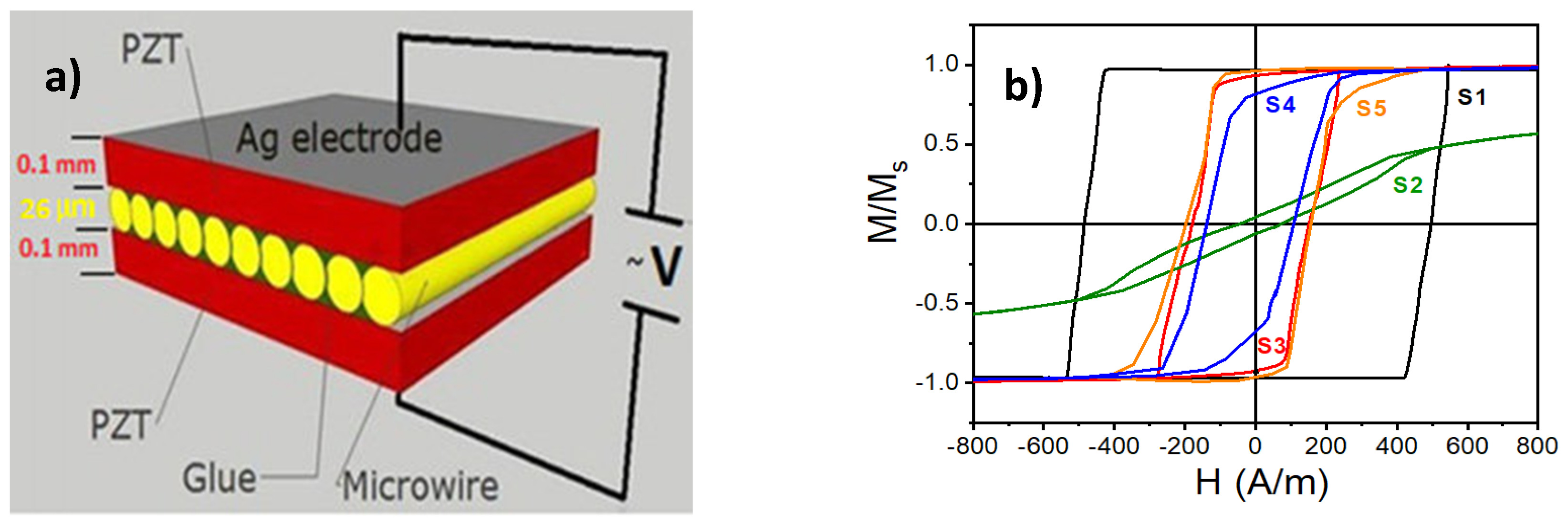
- Amirov, A.; Baraban, I.; Panina, L.; Rodionova, V. Direct magnetoelectric effect in a sandwich structure of pzt and magnetostrictive amorphous microwires. Materials 2020, 13, 916. [Google Scholar] [CrossRef]
- Greve, H.; Woltermann, E.; Quenzer, H.-J.; Wagner, B.; Quandt, E. Giant magnetoelectric coefficients in (Fe90Co10)78Si12B10-AlN thin film composites. Appl. Phys. Lett. 2010, 96, 182501. [Google Scholar] [CrossRef]
- Gaikwad, A.S.; Shirsath, S.E.; Wadgane, S.R.; Kadam, R.H.; Shah, J.; Kotnala, R.K.; Kadam, A.B. Magneto-electric coupling and improved dielectric constant of BaTiO3 and Fe-rich (Co0.7Fe2.3O4) ferrite nano-composites. J. Magn. Magn. Mater. 2018, 465, 508–514. [Google Scholar] [CrossRef]
- Gao, J.; Hasanyan, D.; Shen, Y.; Wang, Y.; Li, J.; Viehland, D. Giant resonant magnetoelectric effect in bi-layered Metglas/Pb(Zr,Ti)O3 composites. J. Appl. Phys. 2012, 112, 104101. [Google Scholar] [CrossRef]
- Palneedi, H.; Maurya, D.; Kim, G.-Y.; Priya, S.; Kang, S.-J.L.; Kim, K.H.; Choi, S.-Y.; Ryu, J. Enhanced off-resonance magnetoelectric response in laser annealed PZT thick film grown on magnetostrictive amorphous metal substrate. Appl. Phys. Lett. 2015, 107, 012904. [Google Scholar] [CrossRef]
- Wen, J.-B.; Zhang, J.-J.; Gao, Y. Multiple broadband magnetoelectric response in Terfenol-D/PZT structure. Chin. Phys. B 2018, 27, 27. [Google Scholar] [CrossRef]
- Wang, Y.; Zhao, X.; Jiao, J.; Zhang, Q.; Di, W.; Luo, H.; Leung, C.M.; Or, S.W.; Or, D.S.W. Lead-free magnetoelectric laminated composite of Mn-doped Na0.5Bi0.5TiO3–BaTiO3 single crystal and Tb0.3Dy0.7Fe1.92 alloy. J. Alloy. Compd. 2010, 496, L4–L6. [Google Scholar] [CrossRef]
- Amorín, H.; Ricote, J.; San-Felipe, I.; Salazar, N.; Del Campo, R.; Barcelay, Y.R.; De La Cruz, J.P.; Ramos, P.; Vila, E.; Castro, A.; et al. Multilayer ceramic magnetoelectric composites with tailored interfaces for enhanced response. ACS Appl. Mater. Interfaces 2017, 9, 39094–39104. [Google Scholar] [CrossRef]
- Feng, M.; Wang, J.-J.; Hu, J.-M.; Wang, J.; Ma, J.; Li, H.-B.; Shen, Y.; Lin, Y.-H.; Chen, L.-Q.; Nan, C.-W. Optimizing direct magnetoelectric coupling in Pb(Zr,Ti)O3/Ni multiferroic film heterostructures. Appl. Phys. Lett. 2015, 106, 072901. [Google Scholar] [CrossRef]
- Wu, D.; Gong, W.; Deng, H.; Li, M. Magnetoelectric composite ceramics of nickel ferrite and lead zirconate titanate via in situ processing. J. Phys. D Appl. Phys. 2007, 40, 5002–5005. [Google Scholar] [CrossRef]
- Palneedi, H.; Reddy, V.A.; Lee, H.-Y.; Choi, J.-J.; Choi, S.-Y.; Chung, S.-Y.; Kang, S.-J.L.; Ryu, J. Strong and anisotropic magnetoelectricity in composites of magnetostrictive Ni and solid-state grown lead-free piezoelectric BZT–BCT single crystals. J. Asian Ceram. Soc. 2017, 5, 36–41. [Google Scholar] [CrossRef]
- Martins, P.; Larrea, A.; Gonçalves, R.; Botelho, G.; Ramana, E.V.; Mendiratta, S.K.; Sebastian, V.; Lanceros-Mendez, S. Novel anisotropic magnetoelectric effect on δ-FeO(OH)/P(VDF-TrFE) multiferroic composites. ACS Appl. Mater. Interfaces 2015, 7, 11224–11229. [Google Scholar] [CrossRef] [PubMed]
- Silva, M.; Martins, P.M.; Lanceros-Méndez, S. Types of polymer-based magnetoelectric materials. In Magnetoelectric Polymer-Based Composites; Wiley: Weinheim, Germany, 2017; pp. 45–63. [Google Scholar]
- Andrade, V.M.; Amirov, A.; Yusupov, D.; Pimentel, B.; Barroca, N.; Pires, A.L.; Belo, J.H.; Pereira, A.M.; Valente, M.A.; Araújo, J.P.; et al. Multicaloric effect in a multiferroic composite of Gd5(Si,Ge)4 microparticles embedded into a ferroelectric PVDF matrix. Sci. Rep. 2019, 9, 18308. [Google Scholar] [CrossRef] [PubMed]
- Guyomar, D.; Matei, D.; Guiffard, B.; Le, Q.; Belouadah, R. Magnetoelectricity in polyurethane films loaded with different magnetic particles. Mater. Lett. 2009, 63, 611–613. [Google Scholar] [CrossRef]
- Feng, L.; Wang, K.; Zhang, X.; Sun, X.; Li, C.; Ge, X.; Ma, Y. Flexible solid-state supercapacitors with enhanced performance from hierarchically graphene nanocomposite electrodes and ionic liquid incorporated gel polymer electrolyte. Adv. Funct. Mater. 2017, 28, 1704463. [Google Scholar] [CrossRef]
- Correia, D.; Martins, P.; Tariq, M.; Esperança, J.; Lanceros-Méndez, S. Low-field giant magneto-ionic response in polymer-based nanocomposites. Nanoscale 2018, 10, 15747–15754. [Google Scholar] [CrossRef] [PubMed]
- Zhay, J. Magnetoelectric Laminated Composites and Devices; Virginia Polytehnic Institute: Blacksburg, VA, USA, 2009. [Google Scholar]
- Mori, K.; Wuttig, M. Magnetoelectric coupling in Terfenol-D/polyvinylidenedifluoride composites. Appl. Phys. Lett. 2002, 81, 100–101. [Google Scholar] [CrossRef]
- Martins, P.; Lanceros-Méndez, S. Polymer-based magnetoelectric materials: To be or not to be. Appl. Mater. Today 2019, 15, 558–561. [Google Scholar] [CrossRef]
- Gutiérrez, J.; Lasheras, A.; Martins, P.; Pereira, N.; Barandiarán, J.M.; Lanceros-Méndez, S. Metallic glass/PVDF magnetoelectric laminates for resonant sensors and actuators: A review. Sensors 2017, 17, 1251. [Google Scholar] [CrossRef]
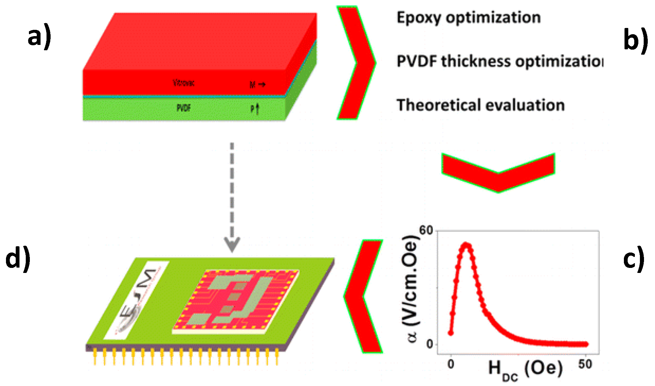
- Silva, M.; Reis, S.; Lehmann, C.; Martins, P.; Lanceros-Méndez, S.; Lasheras, A.; Gutierrez, J.; Barandiaran, J. Optimization of the magnetoelectric response of poly(vinylidene fluoride)/Epoxy/Vitrovac laminates. ACS Appl. Mater. Interfaces 2013, 5, 10912–10919. [Google Scholar] [CrossRef] [PubMed]
- Jing, W.; Fang, F. A flexible multiferroic composite with high self-biased magnetoelectric coupling. Compos. Sci. Technol. 2017, 153, 145–150. [Google Scholar] [CrossRef]
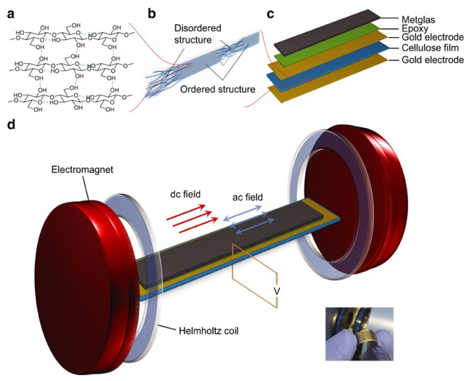
- Zong, Y.; Zheng, T.; Martins, P.; Lanceros-Méndez, S.; Yue, Z.; Higgins, M.J. Cellulose-based magnetoelectric composites. Nat. Commun. 2017, 8, 38. [Google Scholar] [CrossRef]
- Silva, M.P.; Martins, P.; Lasheras, A.; Gutiérrez, J.; Barandiarán, J.M.; Lanceros-Mendez, S. Size effects on the magnetoelectric response on PVDF/Vitrovac 4040 laminate composites. J. Magn. Magn. Mater. 2015, 377, 29–33. [Google Scholar] [CrossRef]
- Martins, P.; Nunes, J.; Oliveira, J.; Peřinka, N.; Lanceros-Mendez, S. Spray-printed magnetoelectric multifunctional composites. Compos. Part B Eng. 2020, 187, 107829. [Google Scholar] [CrossRef]
- Lima, A.C.; Pereira, N.; Policia, R.; Ribeiro, C.; Correia, V.M.G.; Lanceros-Méndez, S.; Martins, P. All-printed multilayer materials with improved magnetoelectric response. J. Mater. Chem. C 2019, 7, 5394–5400. [Google Scholar] [CrossRef]
- Martins, P.; Kolen’Ko, Y.V.; Rivas, J.; Lanceros-Méndez, S. Tailored magnetic and magnetoelectric responses of polymer-based composites. ACS Appl. Mater. Interfaces 2015, 7, 15017–15022. [Google Scholar] [CrossRef]
- Mayeen, A.; Thomas, S.; Rouxel, D.; Philip, J.; Bhowmik, R.N.; Kalarikkal, N.; Jayalakshmy, M.S. Dopamine functionalization of BaTiO3: An effective strategy for the enhancement of electrical, magnetoelectric and thermal properties of BaTiO3-PVDF-TrFE nanocomposites. Dalton Trans. 2018, 47, 2039–2051. [Google Scholar] [CrossRef]
- Chlaihawi, A.; Emamian, S.; Narakathu, B.; Ali, M.; Maddipatla, D.; Bazuin, B.; Atashbar, M.Z. Novel screen printed flexible magnetoelectric thin film sensor. Procedia Comput. Sci. 2016, 168, 684–687. [Google Scholar] [CrossRef]
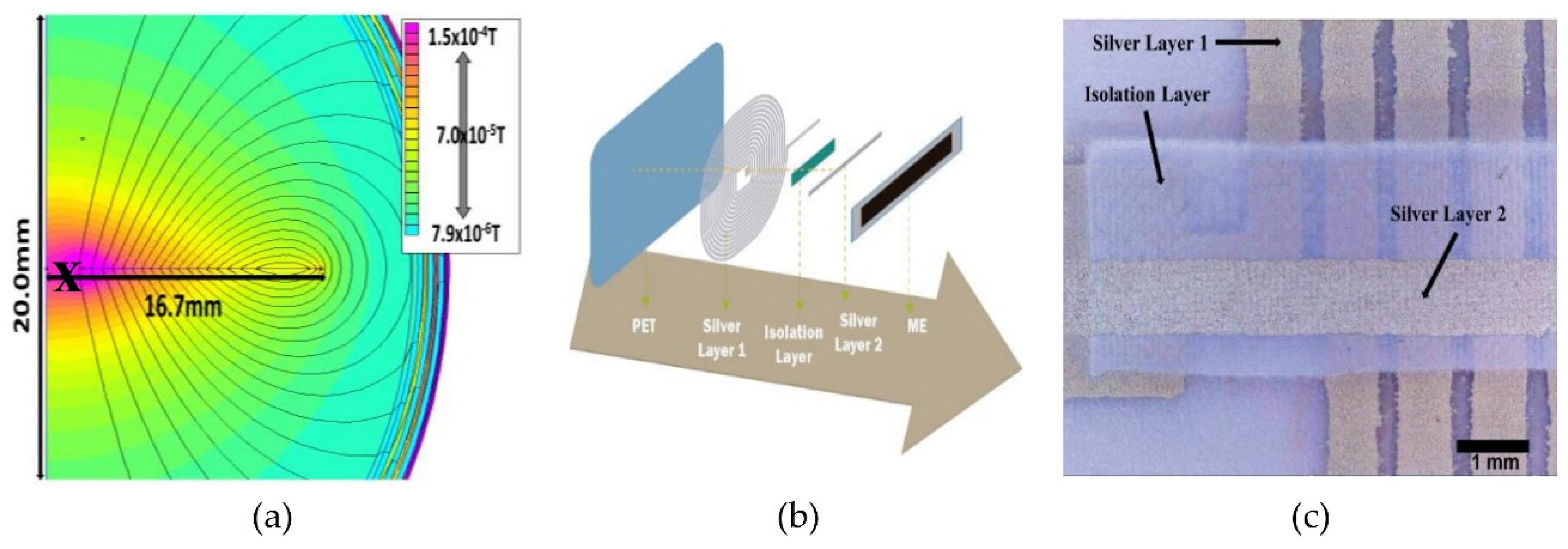
- Reis, S.; Castro, N.; Silva, M.; Correia, V.M.G.; Rocha, J.G.; Martins, P.; Lanceros-Méndez, S. Fabrication and characterization of high-performance polymer-based magnetoelectric DC magnetic field sensors devices. IEEE Trans. Ind. Electron. 2017, 64, 4928–4934. [Google Scholar] [CrossRef]
- Reis, S.; Silva, M.; Castro, N.; Correia, V.M.G.; Gutiérrez, J.; Lasheras, A.; Lanceros-Méndez, S.; Martins, P. Optimized anisotropic magnetoelectric response of Fe61.6Co16.4Si10.8B11.2/PVDF/Fe61.6Co16.4Si10.8B11.2laminates for AC/DC magnetic field sensing. Smart Mater. Struct. 2016, 25, 55050. [Google Scholar] [CrossRef]
- Lu, S.G.; Jin, J.Z.; Zhou, X.; Fang, Z.; Wang, Q.; Zhang, Q.M. Large magnetoelectric coupling coefficient in poly(vinylidene fluoride-hexafluoropropylene)/Metglas laminates. J. Appl. Phys. 2011, 110, 104103. [Google Scholar] [CrossRef]
- Belouadah, R.; Guyomar, D.; Guiffard, B.; Zhang, J.-W. Phase switching phenomenon in magnetoelectric laminate polymer composites: Experiments and modeling. Phys. B Condens. Matter 2011, 406, 2821–2826. [Google Scholar] [CrossRef]
- Garg, N.; Garg, R. Energy harvesting in IoT devices: A survey. In Proceedings of the 2017 International Conference on Intelligent Sustainable Systems (ICISS), New Delhi, India, 7–8 December 2017; Institute of Electrical and Electronics Engineers (IEEE): Piscataway, NJ, USA, 2017; pp. 127–131. [Google Scholar]
- Zakharenko, A.A. On piezogravitocogravitoelectromagnetic shear-horizontal acoustic waves. Can. J. Pure Appl. Sci. 2016, 3, 4011–4028. [Google Scholar]
- Zakharenko, A.A. On necessity of development of instant interplanetary telecommunication based on some gravitational phenomena for remote medical diagnostics and treatment. Can. J. Pure Appl. Sci 2016, 2, 4481–4487. [Google Scholar]
- Ghosh, S.K.; Roy, K.; Mishra, H.K.; Sahoo, M.R.; Mahanty, B.; Vishwakarma, P.N.; Mandal, D. Rollable magnetoelectric energy harvester as a wireless IoT sensor. ACS Sustain. Chem. Eng. 2019, 8, 864–873. [Google Scholar] [CrossRef]
- Yang, J.; Wen, Y.; Li, P.; Dai, X. A magnetoelectric, broadband vibration-powered generator for intelligent sensor systems. Sens. Actuators A Phys. 2011, 168, 358–364. [Google Scholar] [CrossRef]
- Chen, J.; Chen, J.; Cheng, Z.; Zhang, S. The PZT/Ni unimorph magnetoelectric energy harvester for wireless sensing applications. Energy Convers. Manag. 2019, 200, 112084. [Google Scholar] [CrossRef]
- Pereira, N.; Lima, A.C.; Correia, V.; Peřinka, N.; Lanceros-Méndez, S.; Martins, P. Magnetic proximity sensor based on magnetoelectric composites and printed coils. Materials 2020, 13, 1729. [Google Scholar] [CrossRef]
- Friedrich, R.-M.; Zabel, S.; Galka, A.; Lukat, N.; Wagner, J.-M.; Kirchhof, C.; Quandt, E.; Mccord, J.; Selhuber-Unkel, C.; Siniatchkin, M.; et al. Magnetic particle mapping using magnetoelectric sensors as an imaging modality. Sci. Rep. 2019, 9, 1–11. [Google Scholar] [CrossRef] [PubMed]
- Ou, Z.; Lu, C.; Yang, A.; Zhou, H.; Cao, Z.; Zhu, R.; Gao, H. Self-biased magnetoelectric current sensor based on SrFe 12 O 19 /FeCuNbSiB/PZT composite. Sens. Actuators A Phys. 2019, 290, 8–13. [Google Scholar] [CrossRef]
- Chu, Z.; Dong, C.; Tu, C.; Liang, X.; Chen, H.; Sun, C.; Yu, Z.; Dong, S.; Sun, N.X. A low-power and high-sensitivity magnetic field sensor based on converse magnetoelectric effect. Appl. Phys. Lett. 2019, 115, 162901. [Google Scholar] [CrossRef]
- Xu, J.; Leung, C.M.; Zhuang, X.; Li, J.; Bhardwaj, S.; Volakis, J.L.; Viehland, D. A Low frequency mechanical transmitter based on magnetoelectric heterostructures operated at their resonance frequency. Sensors 2019, 19, 853. [Google Scholar] [CrossRef] [PubMed]
- Zaeimbashi, M.; Lin, H.; Dong, C.; Liang, X.; Nasrollahpour, M.; Chen, H.; Sun, N.; Matyushov, A.; He, Y.; Wang, X.; et al. NanoNeuroRFID: A wireless implantable device based on magnetoelectric antennas. IEEE J. Electromagn. RF Microwaves Med. Boil. 2019, 3, 206–215. [Google Scholar] [CrossRef]
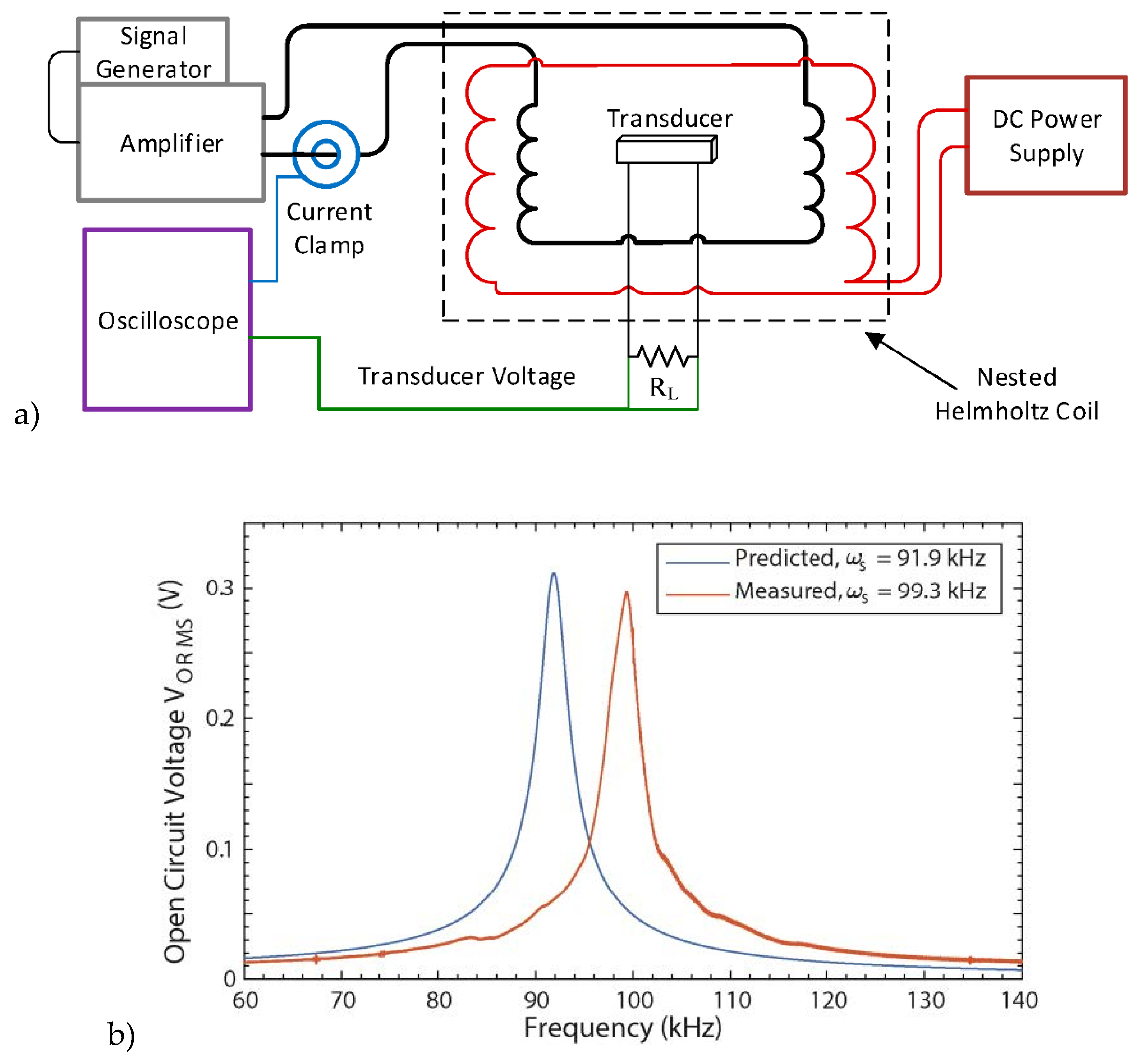
- Rupp, T.; Truong, B.D.; Williams, S.; Roundy, S. Magnetoelectric transducer designs for use as wireless power receivers in wearable and implantable applications. Materials 2019, 12, 512. [Google Scholar] [CrossRef]
- Ahlawat, A.; Satapathy, S.; Shirolkar, M.M.; Li, J.; Khan, A.A.; Deshmukh, P.; Wang, H.; Choudhary, R.J.; Karnal, A.K. Tunable magnetoelectric nonvolatile memory devices based on SmFeO3/P(VDF-TrFE) nanocomposite films. ACS Appl. Nano Mater. 2018, 1, 3196–3203. [Google Scholar] [CrossRef]
- Wei, Y.; Gao, C.; Chen, Z.; Xi, S.; Shao, W.; Zhang, P.; Chen, G.; Li, J. Four-state memory based on a giant and non-volatile converse magnetoelectric effect in FeAl/PIN-PMN-PT structure. Sci. Rep. 2016, 6, 30002. [Google Scholar] [CrossRef]
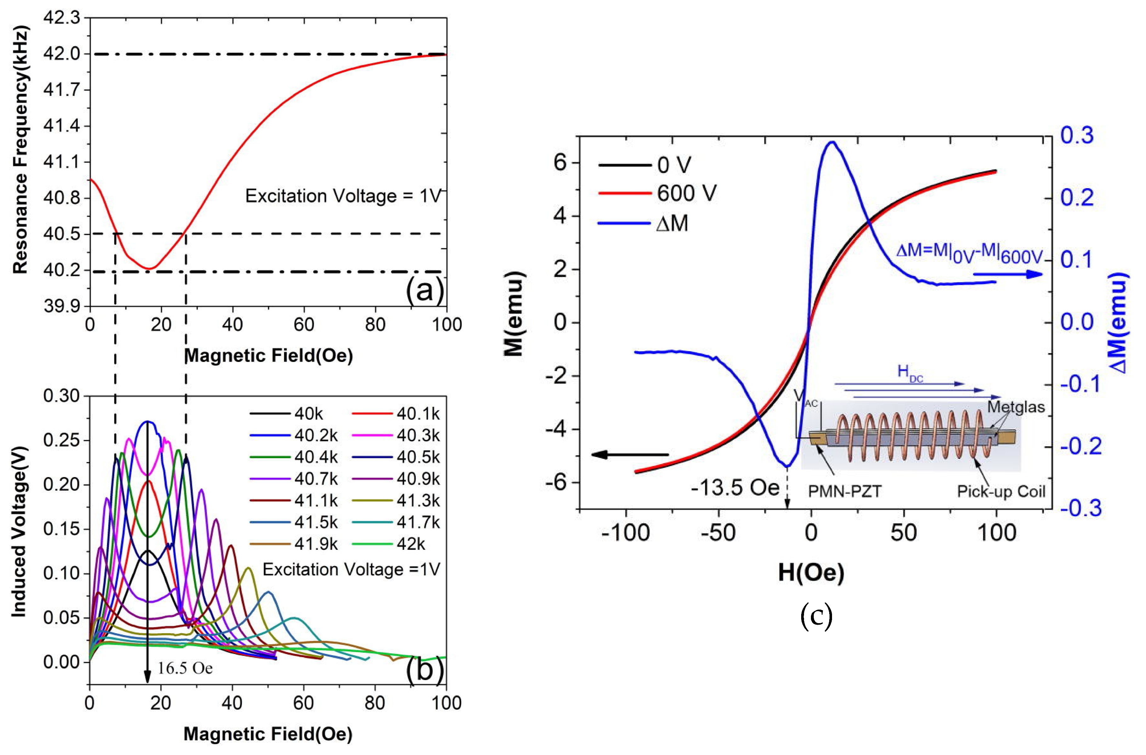
- Sadeghi, M.; Hojjat, Y.; Khodaei, M. Self-sensing feature of the ultrasonic nano-displacement actuator in Metglas/PMN-PT/Metglas magnetoelectric composite. J. Mater. Sci. Mater. Electron. 2019, 31, 740–751. [Google Scholar] [CrossRef]
- Wang, Y.; Li, J.; Viehland, D. Magnetoelectrics for magnetic sensor applications: Status, challenges and perspectives. Mater. Today 2014, 17, 269–275. [Google Scholar] [CrossRef]
- Murzin, D.; Mapps, D.J.; Levada, K.; Belyaev, V.; Omelyanchik, A.; Panina, L.V.; Rodionova, V. Ultrasensitive magnetic field sensors for biomedical applications. Sensors 2020, 20, 1569. [Google Scholar] [CrossRef] [PubMed]
- Ribeiro, R.R.; Lameiras, R. Evaluation of low-cost MEMS accelerometers for SHM: Frequency and damping identification of civil structures. Lat. Am. J. Solids Struct. 2019, 16, 16. [Google Scholar] [CrossRef]
- Narita, F.; Fox, M. A Review on piezoelectric, magnetostrictive, and magnetoelectric materials and device technologies for energy harvesting applications. Adv. Eng. Mater. 2017, 20, 1700743. [Google Scholar] [CrossRef]
- Faria, M.; Björnmalm, M.; Thurecht, K.J.; Kent, S.J.; Parton, R.G.; Kavallaris, M.; Johnston, A.P.R.; Gooding, J.J.; Corrie, S.R.; Boyd, B.; et al. Minimum information reporting in bio–nano experimental literature. Nat. Nanotechnol. 2018, 13, 777–785. [Google Scholar] [CrossRef] [PubMed]
- Lee, H.; Shin, T.-H.; Cheon, J.; Weissleder, R. Recent developments in magnetic diagnostic systems. Chem. Rev. 2015, 115, 10690–10724. [Google Scholar] [CrossRef]


| αp (C/m2·Oe) | PU 2%Ni | PU 2%Fe3O4 | PU 2%TeD |
|---|---|---|---|
| f1 = 120 Hz | 6.2 × 10⁻¹¹ | 1.2 × 10⁻¹⁰ | 4 × 10⁻¹¹ |
| f2 = 1 kHz | 5.3 × 10⁻¹⁰ | 6.15 × 10⁻¹⁰ | 2.2 × 10⁻¹⁰ |
| ME Coupling | Device Type | Ref |
|---|---|---|
| Direct coupling | Nanogenerator | [98] |
| Energy harvesting multi-cantilever beam | [99] | |
| For energy harvesting in wireless sensing | [100] | |
| Magnetic proximity sensor | [101] | |
| Magnetic particle mapping | [102] | |
| Self-biased ME cantilever sensor | [103] | |
| Wireless power receiver | [107] | |
| Self-sensing actuator | [110] | |
| Converse coupling | Magnetic field sensor | [104] |
| Low frequency transmitter | [105] | |
| Antenna array | [106] | |
| Flexible memory | [108] | |
| Four-state memory | [109] |
© 2020 by the authors. Licensee MDPI, Basel, Switzerland. This article is an open access article distributed under the terms and conditions of the Creative Commons Attribution (CC BY) license (http://creativecommons.org/licenses/by/4.0/).
Share and Cite
Pereira, N.; Lima, A.C.; Lanceros-Mendez, S.; Martins, P. Magnetoelectrics: Three Centuries of Research Heading Towards the 4.0 Industrial Revolution. Materials 2020, 13, 4033. https://doi.org/10.3390/ma13184033
Pereira N, Lima AC, Lanceros-Mendez S, Martins P. Magnetoelectrics: Three Centuries of Research Heading Towards the 4.0 Industrial Revolution. Materials. 2020; 13(18):4033. https://doi.org/10.3390/ma13184033
Chicago/Turabian StylePereira, Nélson, Ana Catarina Lima, Senentxu Lanceros-Mendez, and Pedro Martins. 2020. "Magnetoelectrics: Three Centuries of Research Heading Towards the 4.0 Industrial Revolution" Materials 13, no. 18: 4033. https://doi.org/10.3390/ma13184033
APA StylePereira, N., Lima, A. C., Lanceros-Mendez, S., & Martins, P. (2020). Magnetoelectrics: Three Centuries of Research Heading Towards the 4.0 Industrial Revolution. Materials, 13(18), 4033. https://doi.org/10.3390/ma13184033