Small Caliber Bulletproof Test of Warships’ Hulls


Abstract
1. Introduction
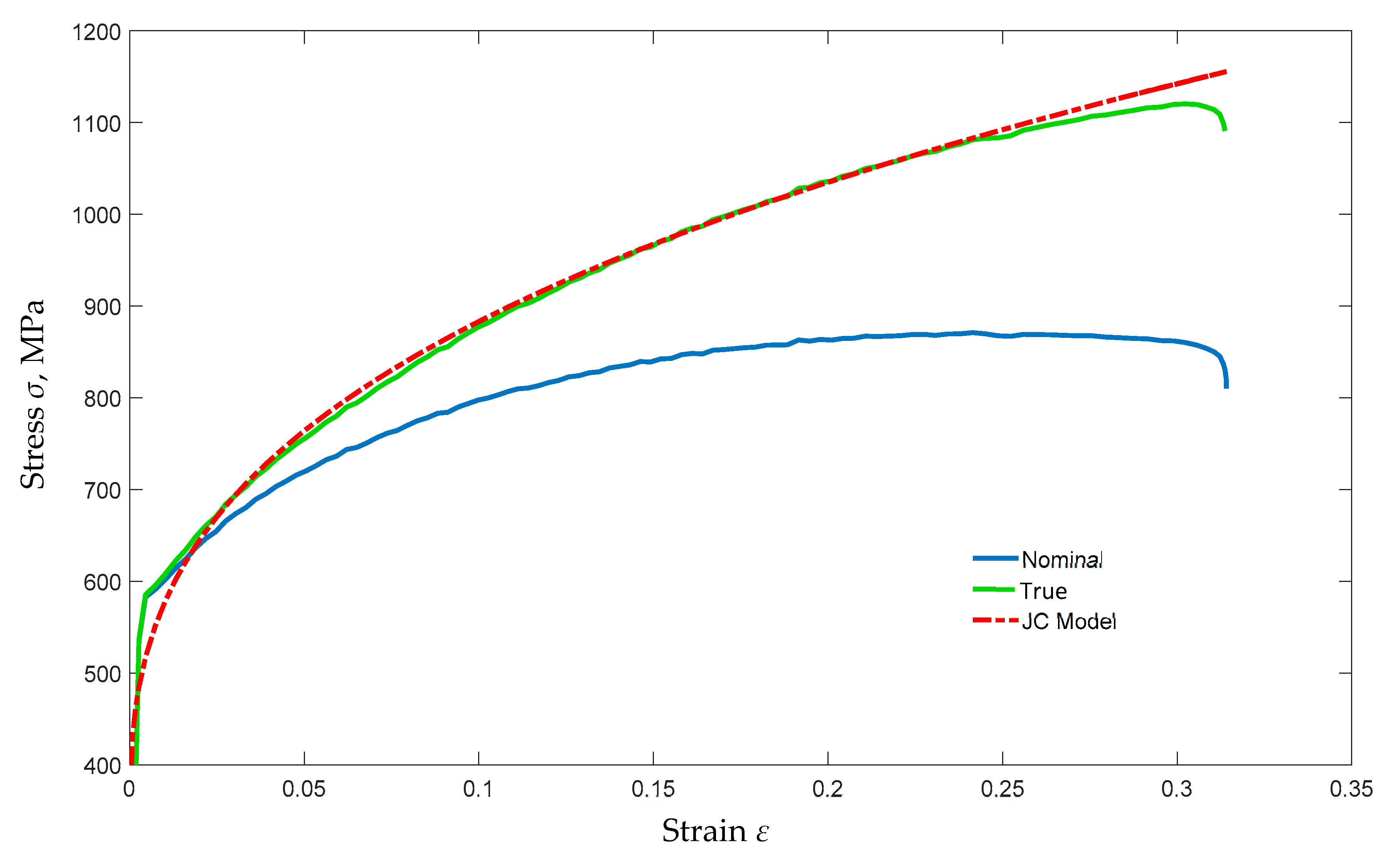
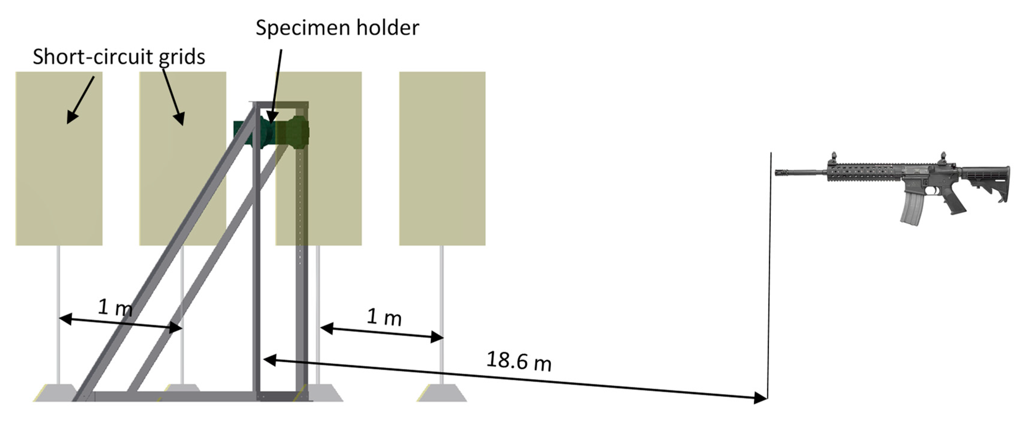
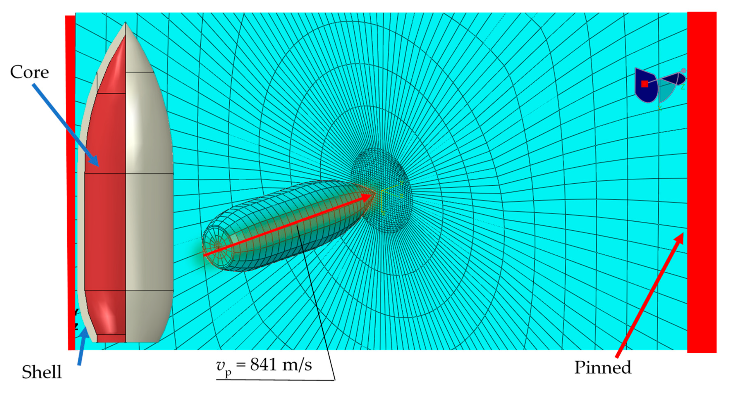
2. Materials and Methods
- A—material constant of the J-C model;
- B—hardening parameter of the J-C model;
- n—strengthening exponent of the J-C model;
- C—J-C strain rate parameter;
- d1, d2, d3—J-C failure criterion;
- ufailure—displacement at failure;
- μ—coefficient of friction.
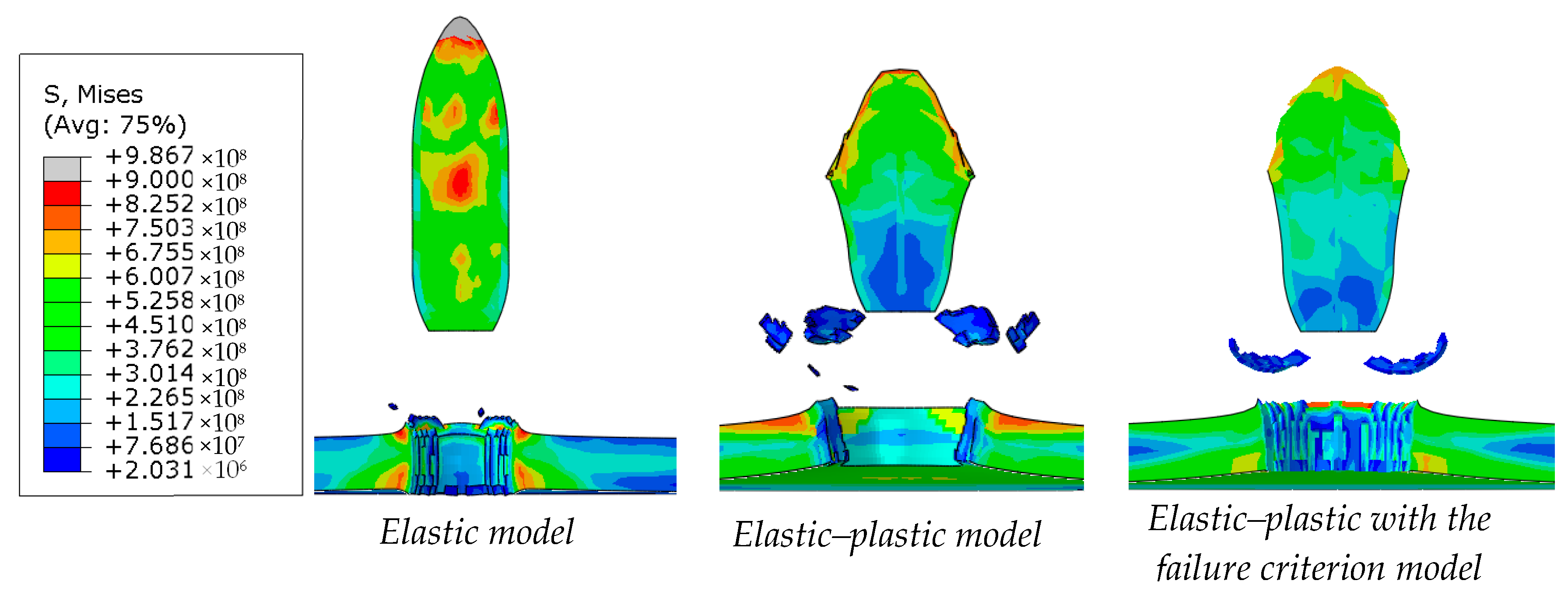
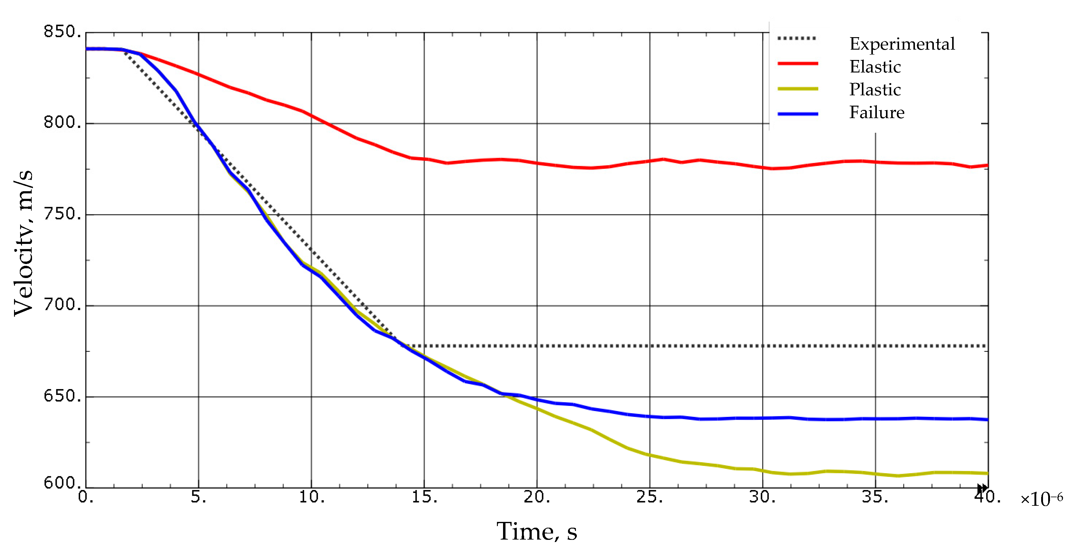
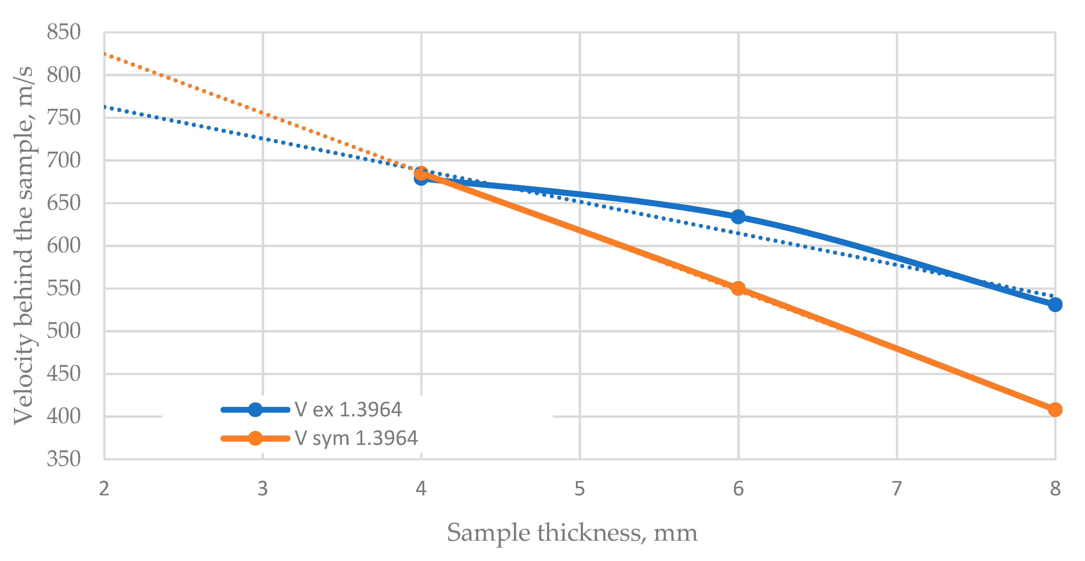
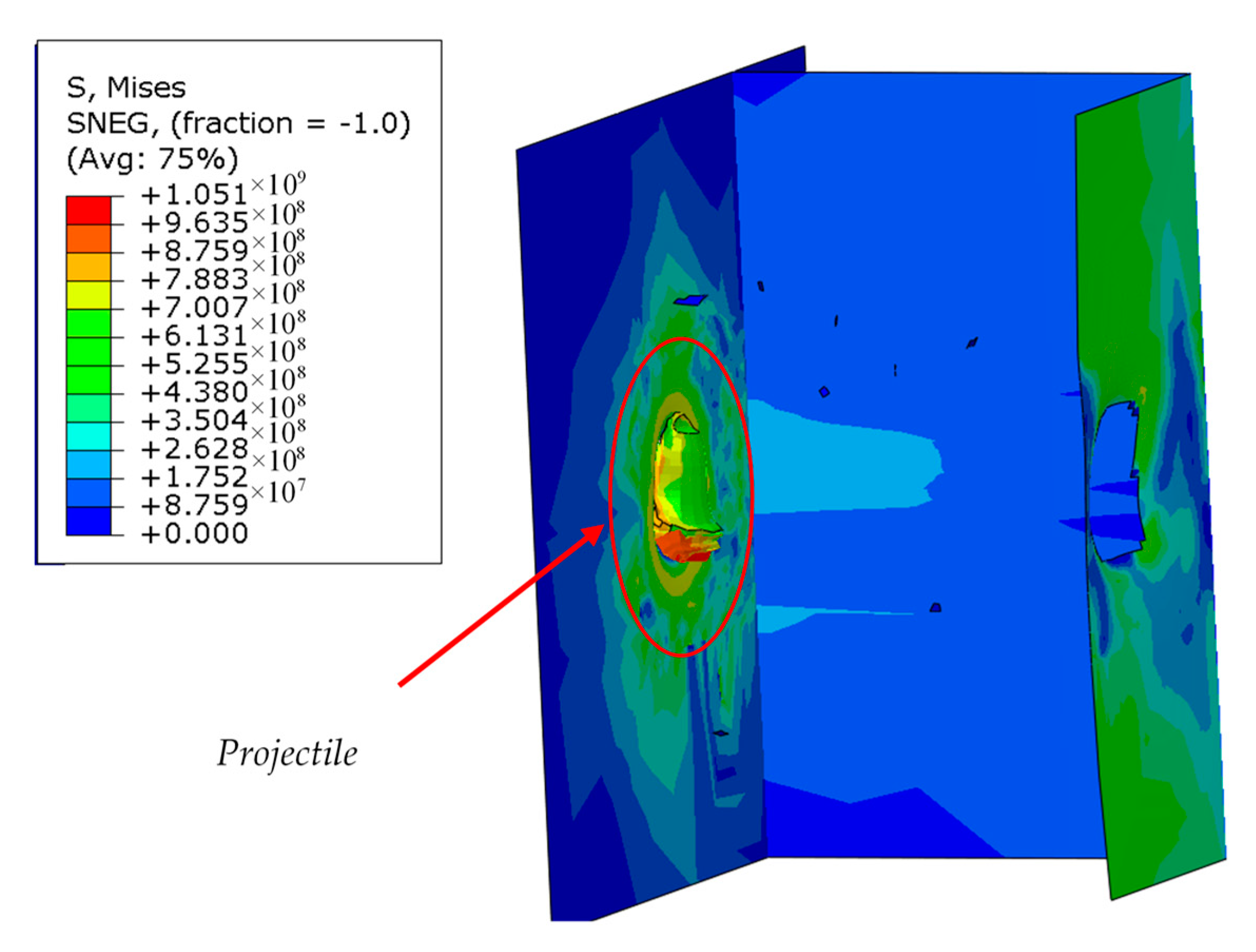
3. Results
4. Discussion
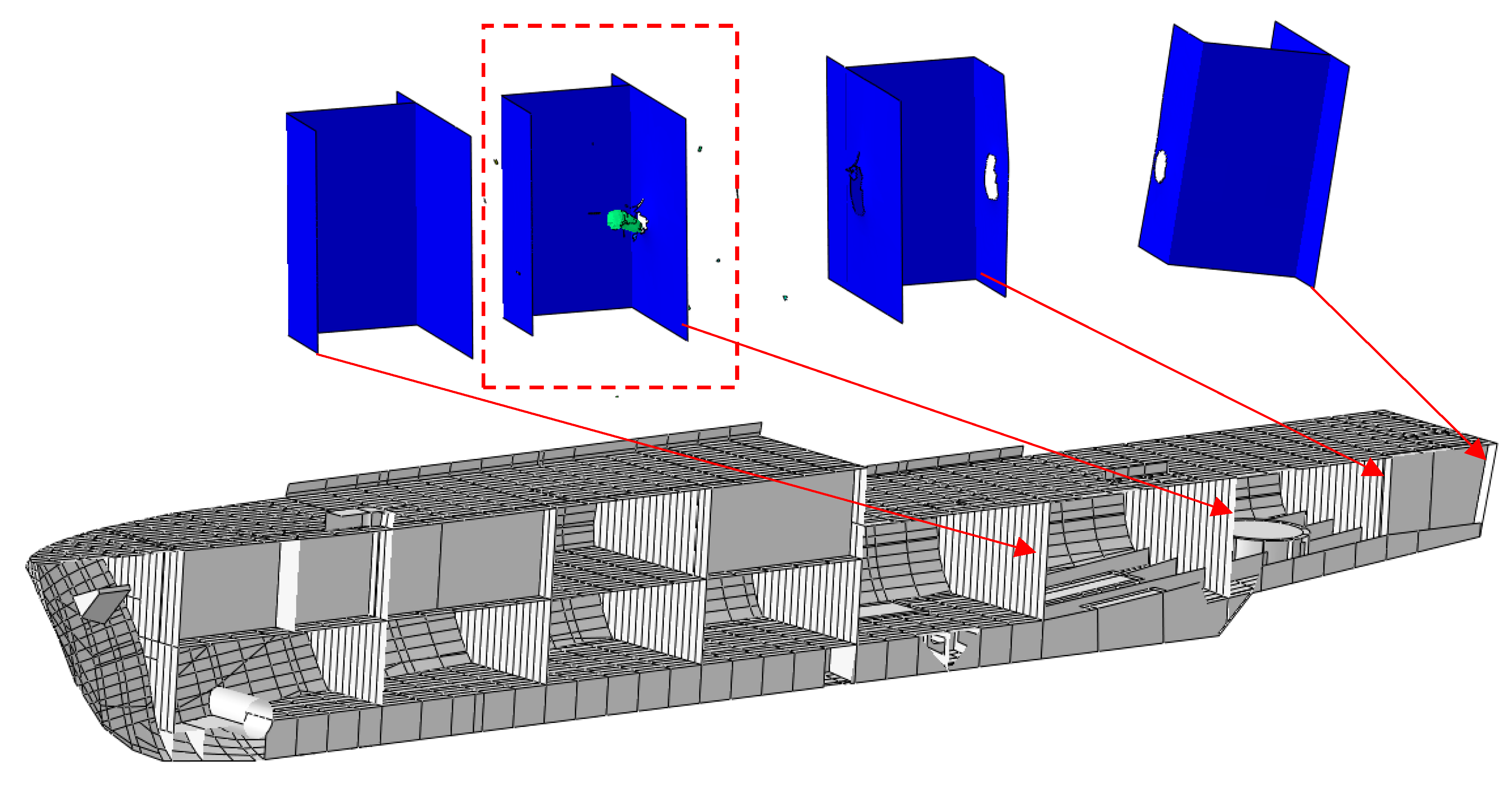
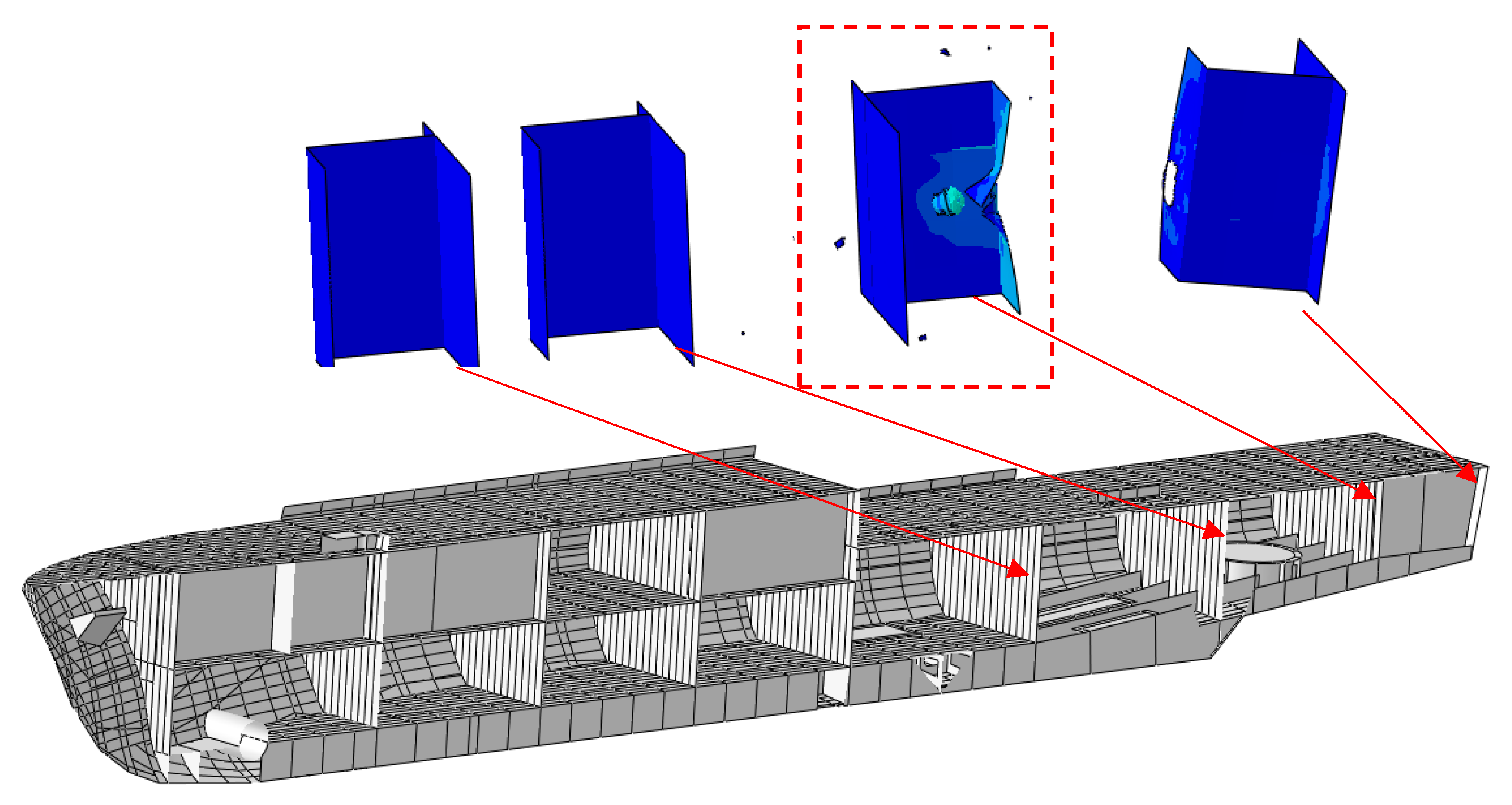
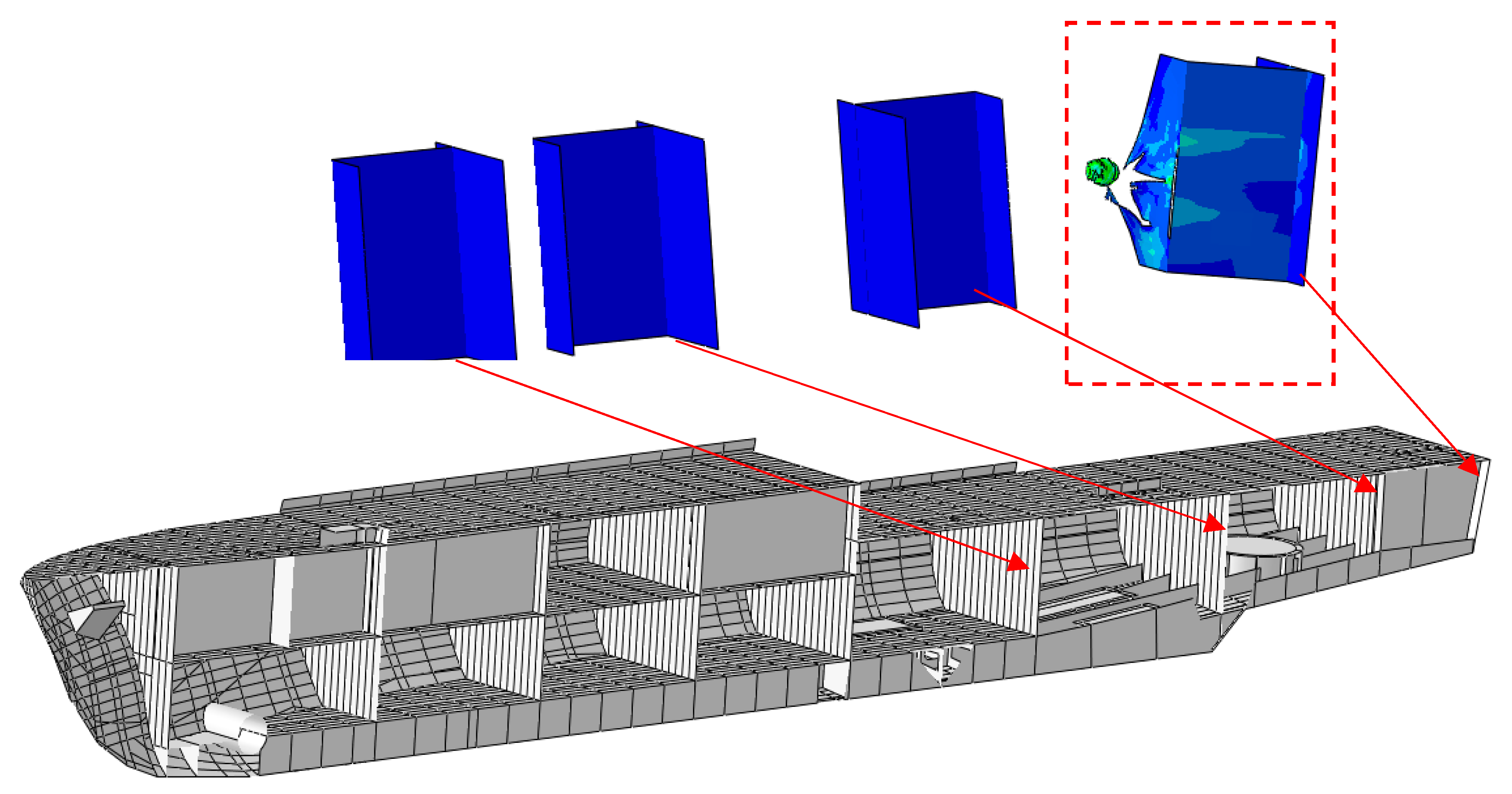
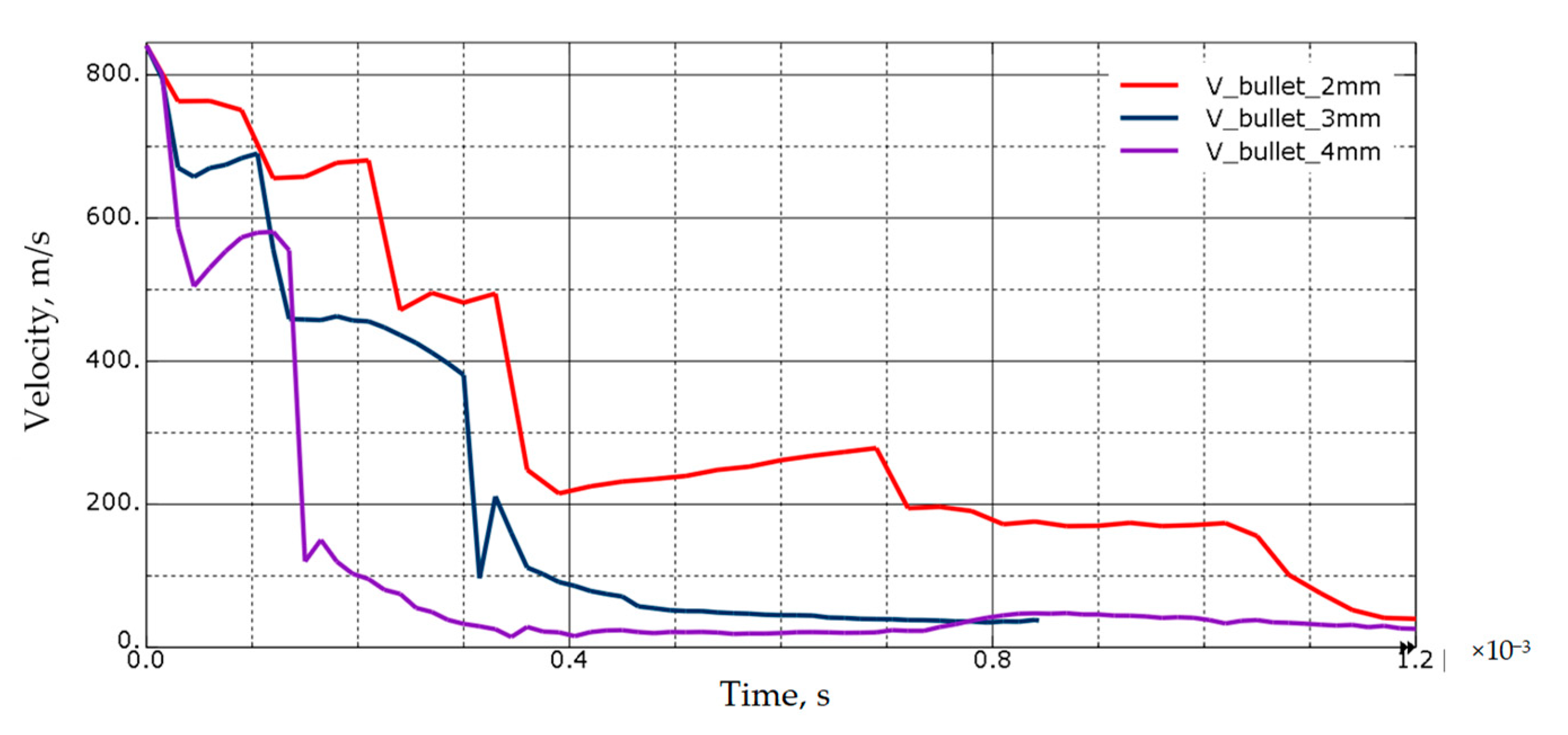
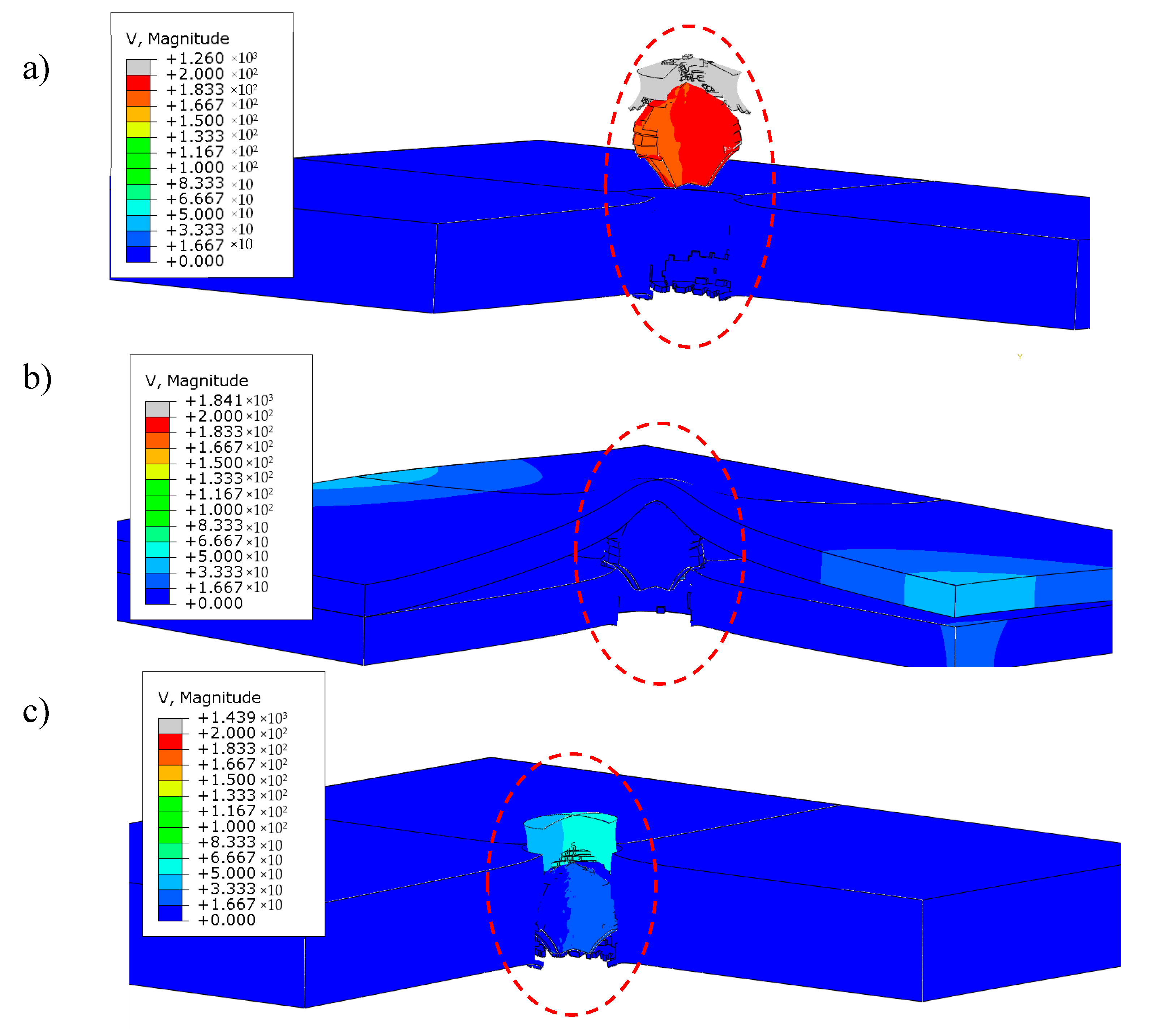
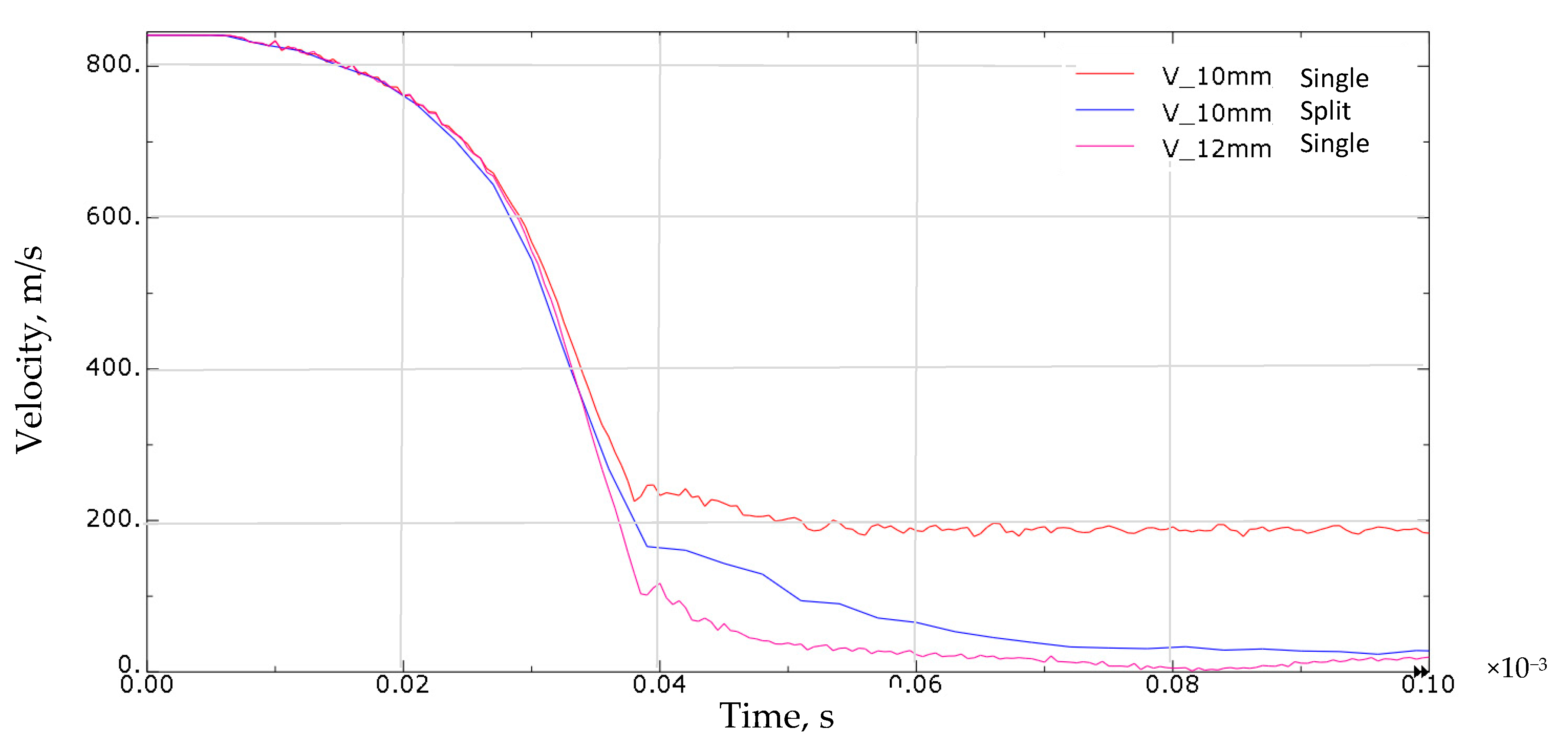
- The projectile impact on the single sample structure results in the sample puncture. The projectile made a cork that moved with it at a speed of around 200 m/s (Figure 14a);
- Shooting split samples did not show any breakthrough. The projectile was stopped in the space between the plates (Figure 14b);
- Dividing the sheets by thickness allowed us to increase its bullet resistance to a level comparable to a sheet with a thickness of 12 mm (Figure 14c).
Author Contributions
Funding
Conflicts of Interest
References
- Garzke, W.H.; Dulin, R.O. Battleships: Axis and Neutral Battleships in World War II; Naval Institute Press: Annapolis, MD, USA, 1985; ISBN 978-0-87021-101-0. [Google Scholar]
- Kubiak, K. “Broń nieśmiercionośna” we współczesnych konfliktach zbrojnych. [“Non-lethal weapons” in contemporary armed conflicts]. Zeszyty Naukowe. Wyd. 2008, 1, 72–80. (In Polish) [Google Scholar]
- Szudrowicz, M.; Rutyna, K.; Jamroziak, K. Osłony balistyczne—Laminaty na bazie tkanin aramidowych [Ballistic shields—laminates based on aramid fabrics]. Probl. Tech. Uzbroj. 2005, 34, 207–216. (In Polish) [Google Scholar]
- Carbajal, L.; Jovicic, J.; Kuhlmann, H. Assault Riffle Bullet-Experimental Characterization and Computer (FE) Modeling. In Experimental and Applied Mechanics; Springer: New York, NY, USA, 2011; Volume 6, pp. 651–668. [Google Scholar]
- Nyanor, P.; Hamada, A.; Hassan, M.A.-N. Ballistic Impact Simulation of Proposed Bullet Proof Vest Made of TWIP Steel, Water and Polymer Sandwich Composite Using FE-SPH Coupled Technique. Key Eng. Mater. 2018, 786, 302–313. [Google Scholar] [CrossRef]
- Sperski, M. Model obliczeniowy do oszacowania odporności balistycznej pancerzy stalowych [Calculation model to assess the ballistic resistance of steel armor]. Sci. J. Pol. Nav. Acad. 2009, 50, 51–59. (In Polish) [Google Scholar]
- Kiciński, R.; Szturomski, B.; Jurczak, W. Determination of Material Characteristics Necessary for Modelling of Marine Structures Exposed to Small-Calibre Bullet. J. KONES 2019, 26, 105–111. [Google Scholar] [CrossRef]
- Cho, H.; Lee, J.; Hong, S.; Kim, S. Bulletproof Performance of Composite Plate Fabricated Using Shear Thickening Fluid and Natural Fiber Paper. Appl. Sci. 2019, 10, 88. [Google Scholar] [CrossRef]
- Zhang, C.; Rao, Y.; Li, Z.; Li, W. Low-Velocity Impact Behavior of Interlayer/Intralayer Hybrid Composites Based on Carbon and Glass Non-Crimp Fabric. Materials 2018, 11, 2472. [Google Scholar] [CrossRef] [PubMed]
- Jurczak, W.; Zatorski, Z.; Szturomski, B.; Świątek, K.; Flis, L.; Zdunek, J. Wyznaczanie Rzeczywistych, Dynamicznych Charakterystyk Wytrzymałościowych Stali Austenitycznej Oraz Stopów Aluminium—Sprawozdanie z Pracy Badawczej Statutowej pk. Austenka [Determination of True and Dynamic Strength Characteristics of Austenitic Steel and Aluminum Alloys—Report on Statutory Research under the Austenka Code; Polish Naval Academy: Gdynia, Poland, 2019. (In Polish) [Google Scholar]
- Sompoliński, P. NITRONIC 50®, XM-19, UNS S20910—Stal Nierdzewna. Available online: https://virgamet.pl/nitronic-50-hs-shs-uns-s20910-xm-19-stal-nierdzewna-niemagnetyczna (accessed on 18 June 2020).
- Polish Norm PN-EN ISO 6892-1:2016. Metallic materials. Tensile testing. In Part 1—Method of Test at Room Temperature; Polish Committee for Standardization: Warszawa, Poland, 2016. [Google Scholar]
- Lincoln Electric Katalog Materiałów Spawalniczych, Lincoln Electric [Lincoln Electric Welding Consumables Catalog]. Available online: https://www.lincolnelectric.com/assets/EU/PL/consumables-catalogue-pl.pdf (accessed on 31 August 2020).
- Metalcor GmbH, Essen, Germany Metalcor 1.3964, Alloy 50—Product Catalog. Available online: http://www.metalcor.de/en/datenblatt/81/ (accessed on 31 August 2020).
- Kiciński, R.; Jurczak, W. Mechanical properties of welded joint of 1.3964 steel for computer aided engineeering (CAE) purposes. Sci. J. Pol. Nav. Acad. 2020, 220, 15–28. [Google Scholar]
- Szturomski, B. Engineering Application of FEM in Problems of Solid Mechanics on the Example of the ABAQUS Program; Wydawnictwo Akademickie AMW: Gdynia, Poland, 2013. [Google Scholar]
- Szturomski, B. Dynamic characteristics of high-quality steel in the Johnson-Cook model for the needs of fast-changing processes CAE simulations. Logistyka 2015, 236, 31–38. [Google Scholar]
- Kong, L.Z.; Shuai, J.; Zhou, X.Y.; Huang, K.; Yu, G.J. True stress-logarithmic strain curves test of pipeline steels using 3D digital image correlation. In Optoelectronics and Advanced Materials—Rapid Communications; National Institute of Optoelectronics: Măgurele, Romania, 2015; Volume 9. [Google Scholar]
- Johnson, G.R.; Cook, W.H. A constitutive model and data for metals subjected to large strains, high strain rates and high. In Proceedings of the 7th International Symposium on Ballistics, Hague, The Netherlands, 19–21 April 1983; Volume 21, pp. 541–547. [Google Scholar]
- Leszek Flis Identyfikacja parametrów równania konstytutywnego Johnsona-Cook’a w odniesieniu do symulacji MES [Identification of parameters of the Johnson-Cook constitutive equation for FEM simulation]. In Proceedings of the XIII Konferencji n.t. Techniki Komputerowe w Inżynierii, Konina, Poland, 6–9 May 2014. (In Polish).
- Abaqus 6.14 Theory Manual; Simulia; Dassault Systems: Johnston, RI, USA, 2014.
- Kohnke, P. Ansys Theory Reference; Relase 5.6; Ansys: Canonsburg, PA, USA, 1999. [Google Scholar]
- Kondo, D.; Welemane, H.; Cormery, F. Basic concepts and models in continuum damage mechanics. Revue Eur. Génie Civ. 2007, 11, 927–943. [Google Scholar] [CrossRef]
- Skrzypek, J.J.; Ganczarski, A. Modeling of Material Damage and Failure of Structures. In Foundations of Engineering Mechanics; Springer: Berlin/Heidelberg, Germany, 1999; ISBN 978-3-642-08353-2. [Google Scholar]
- Banerjee, A.; Dhar, S.; Acharyya, S.; Datta, D.; Nayak, N. Determination of Johnson cook material and failure model constants and numerical modelling of Charpy impact test of armour steel. Mater. Sci. Eng. A 2015, 640, 200–209. [Google Scholar] [CrossRef]
- Zhang, Y.C.; Outeiro, J.; Mabrouki, T. On the Selection of Johnson-cook Constitutive Model Parameters for Ti-6Al-4V Using Three Types of Numerical Models of Orthogonal Cutting. Procedia CIRP 2015, 31, 112–117. [Google Scholar] [CrossRef]
- Szturomski, B.; Świątek, K.; Jurczak, W. Determination of Dynamic Characteristics of Austenitic Steel to be Utilized in Fem Simulation and its Verification. Zesz. Nauk. Akad. Mar. Wojen 2018, 213, 35–42. [Google Scholar] [CrossRef][Green Version]
- Next Stages of Construction of “KORMORAN II” Ships. Remontowa Shipbuilding. Available online: http://www.remontowa-rsb.pl/aktualnosci/kolejne-etapy-budowy-okretow-typu-kormoran-ii/ (accessed on 31 August 2020).
- The “Kormoran II” Minehunter among the Highest Export Potential Products of the Polish Defense Industry. Available online: https://ctm.gdynia.pl/en/the-kormoran-ii-minehunter-among-the-highest-export-potential-products-of-the-polish-defense-industry/ (accessed on 29 June 2020).
- Szturomski, B.; Grzadziela, A.; Kiciński, R. Analysis of the State of Stress in the Hull of the Ship Kormoran II Loaded with Non-Contact Mine Explosion. Solid State Phenom. 2015, 236, 3–13. [Google Scholar] [CrossRef]
- Haag, M.G.; Haag, L.C. Shooting Incident Reconstruction. In Shooting Incident Reconstruction; Academic Press: Amsterdam, The Netherlands; Boston, MA, USA; San Diego, CA, USA, 2011. [Google Scholar]
- Dobrociński, S.; Fila, J.; Jurczak, W.; Kolenda, J. Impact and Ballistic Resistance of a New Aluminum Alloy and Composites Making Use of It; Praca statutowa AMW; Polish Naval Academy: Gdynia, Poland, 1999. (In Polish) [Google Scholar]
- Jurczak, W. Impact and Ballistic Resistance of a New Aluminium Alloy for Ship Construction Elements. Pol. Marit. Res. 2015, 22, 72–78. [Google Scholar] [CrossRef]


| EN-10088 | 1.3964/ X2CrNiMoNNb 21-16-5-3 | ||
|---|---|---|---|
| ASTM | XM-19 | ||
| Chemical Composition | Catalog [14] | According to the Metallurgical Certificate | |
| C | % | Max. 0.03 | 0.012 |
| Mn | % | 4÷6 | 4.42 |
| Cr | % | 20÷21.5 | 20.32 |
| Ni | % | 15 ÷17 | 15.46 |
| Mo | % | 3÷3.5 | 3.15 |
| Nb | % | Max. 0.25 | 0.12 |
| N | % | <0.11 | 0.305 |
| Fe | % | residue | residue |
| Si | % | – | 0.36 |
| P + S | % | Max. 0.019 + 0.0004 | |
| Sample Thickness mm | Sample Characteristics mm | Gap between Samples | vp m/s In Front of the Specimen | vk m/s Behind the Specimen | vkaverage m/s | |
|---|---|---|---|---|---|---|
| 4 | single | - | None | 840.9 | 683.06 | 678.91 |
| 4 | single | - | None | 834.8 | 674.76 | |
| 6 | single | - | None | 842.7 | 642.67 | 633.78 |
| 6 | single | - | None | 839.9 | 626.57 | |
| 6 | single | - | None | 843.7 | 632.11 | |
| 8 | sgle | - | None | 838 | 523.29 | 530.96 |
| 8 | single | - | None | 831 | 530.22 | |
| 8 | single | - | None | 836.6 | 539.37 | |
| 8 | 4+4 | Gap | 20 mm | 840 | 464.25 | 461.69 |
| 8 | 4+4 | Gap | 20 mm | 841 | 459.14 | |
| 8 | 4+4 | Gap | 40 mm | 856 | 456.62 | 456.00 |
| 8 | 4+4 | Gap | 40 mm | 840 | 455.37 | |
| 8 | 4+4 | Gap | 60 mm | 842 | 413.56 | 417.04 |
| 8 | 4+4 | Gap | 60 mm | 843 | 420.52 | |
| 8 | 4+4 | Gap | 80 mm | 840 | 410.17 | 410.17 |
| 8 | 4+4 | Gap | 100 mm | 835 | 420.52 | 420.52 |
| 8 | 4+4 | Gap | 120 mm | 839 | 448.83 | 448.83 |
| 8 | 4+4 | Gap | 140 mm | 845 | 423.73 | 423.73 |
| Material | Elastic | J-C Plasticity | J-C Failure | ||||||
|---|---|---|---|---|---|---|---|---|---|
| E | ν | A | B | n | C [27] | d1 | d2 | d3 | |
| 1.3964 | 240 GPa | 0.3 | 302 | 1250 | 0.3334 | 0.006 | 0.02 | 0.05 | 0.5 |
| Part of the Projectile | Elastic | J-C Plasticity | J-C Damage Criterion | ||||||
|---|---|---|---|---|---|---|---|---|---|
| E | ν | A | B | n | C | d1 | d2 | d3 | |
| Core | 210 GPa | 0.3 | 234.4 | 413.8 | 0.25 | 0.0033 | 5.625 | 0.3 | −7.2 |
| Shell | 120 GPa | 0.33 | 448.2 | 303.4 | 0.15 | 0.0033 | 2.25 | 0.0005 | −3.6 |
© 2020 by the authors. Licensee MDPI, Basel, Switzerland. This article is an open access article distributed under the terms and conditions of the Creative Commons Attribution (CC BY) license (http://creativecommons.org/licenses/by/4.0/).
Share and Cite
Kiciński, R.; Kubit, A. Small Caliber Bulletproof Test of Warships’ Hulls. Materials 2020, 13, 3848. https://doi.org/10.3390/ma13173848
Kiciński R, Kubit A. Small Caliber Bulletproof Test of Warships’ Hulls. Materials. 2020; 13(17):3848. https://doi.org/10.3390/ma13173848
Chicago/Turabian StyleKiciński, Radosław, and Andrzej Kubit. 2020. "Small Caliber Bulletproof Test of Warships’ Hulls" Materials 13, no. 17: 3848. https://doi.org/10.3390/ma13173848
APA StyleKiciński, R., & Kubit, A. (2020). Small Caliber Bulletproof Test of Warships’ Hulls. Materials, 13(17), 3848. https://doi.org/10.3390/ma13173848