Microstructure and Mechanical Properties of Annealed WC/C PECVD Coatings Deposited Using Hexacarbonyl of W with Different Gases

 ,
,  , , ,
, , , 
Abstract
1. Introduction
2. Materials and Methods
2.1. Sample Preparation
2.2. Deposition of Coatings and Annealing
2.3. Nanohardness and Young′s Modulus
2.4. SEM, AFM, XRD, and GDOES Analyses
2.5. Coefficient of Friction
3. Results and Discussion
3.1. Optimization of the Deposited Coatings′ Parameters
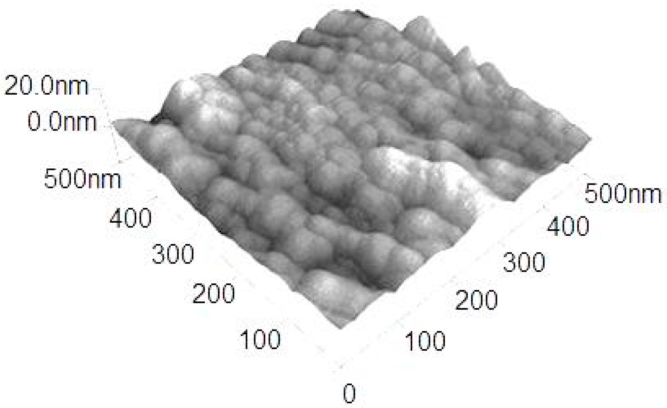
3.1.1. Microstructure
3.1.2. Indentation Hardness and Young′s Modulus
3.1.3. Coefficient of Friction
3.2. Ar Effect
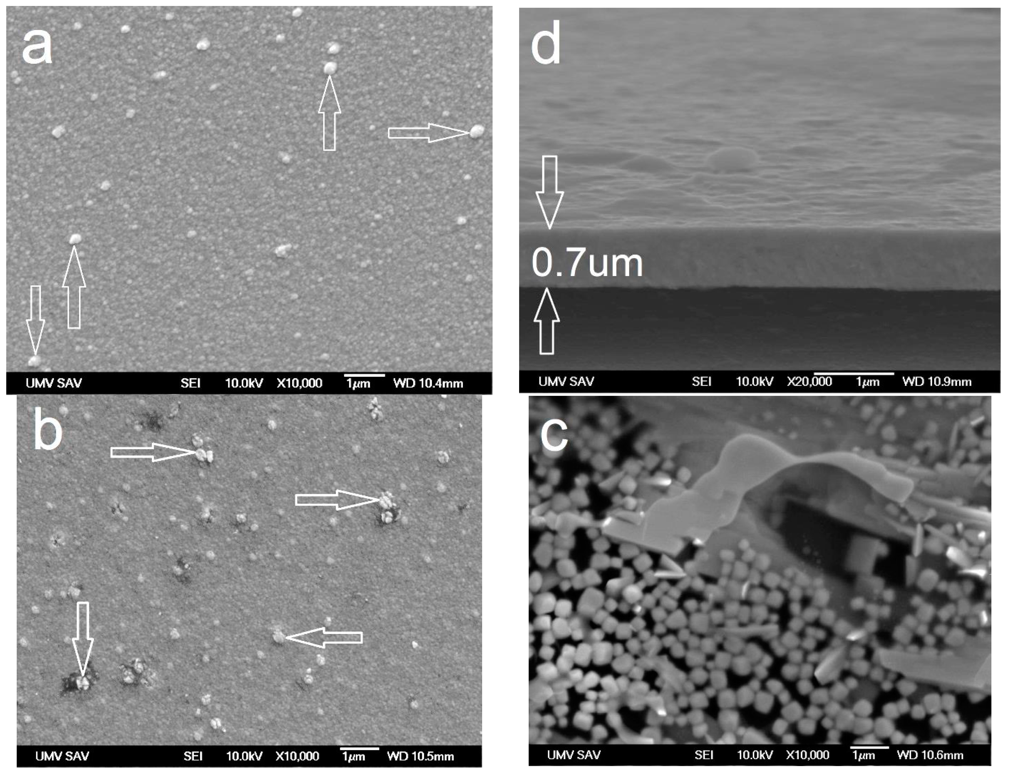
3.2.1. Morphology, Phase Analysis, and Chemical Composition
3.2.2. Mechanical and Tribological Behavior
3.3. N2 Effect
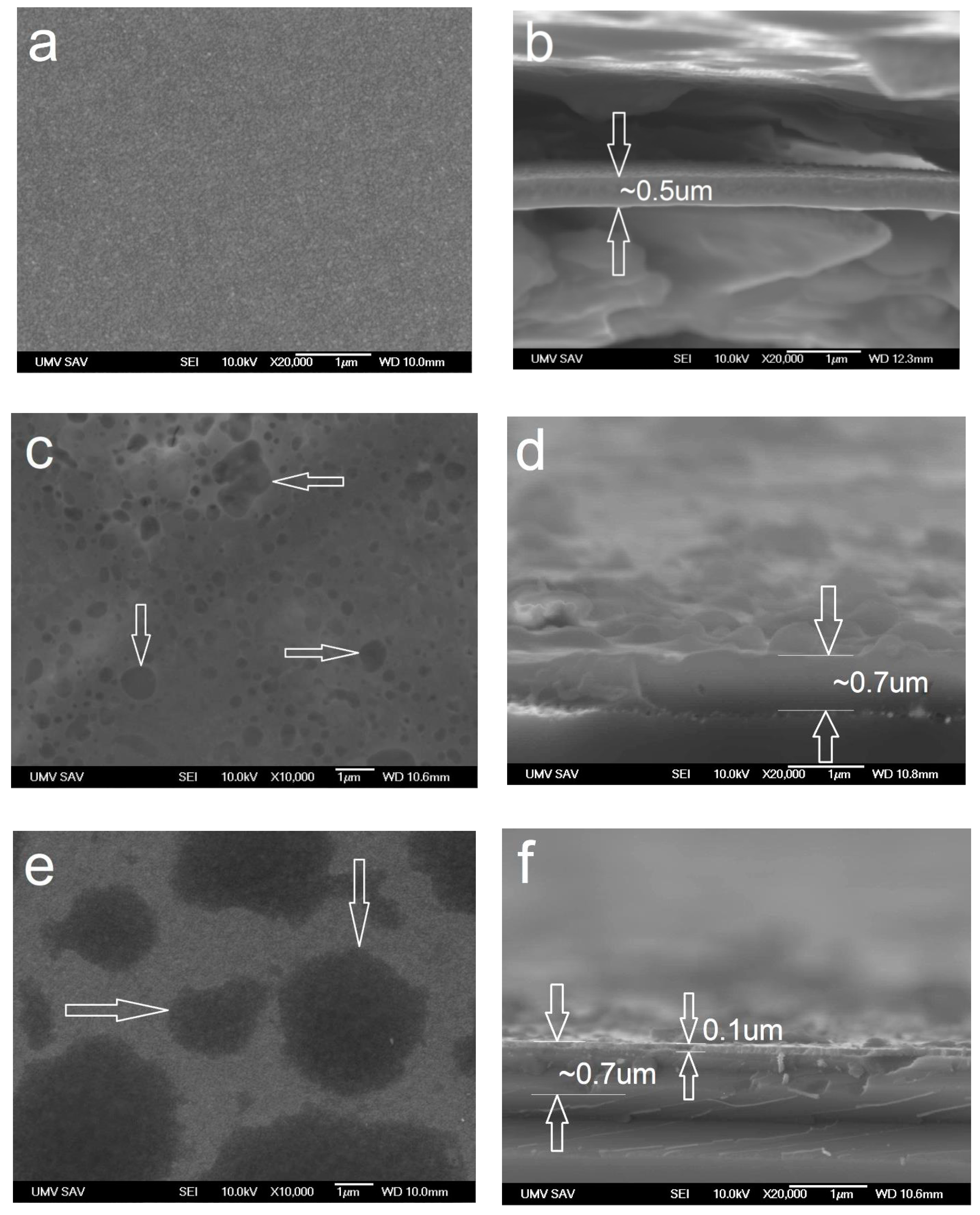
3.3.1. Morphology
3.3.2. Phase Analysis
3.3.3. Mechanical Properties and COF
4. Conclusions
- Maximal values (deposition with W carbonyl as precursor) were HIT = 20.9 ± 2 GPa and EIT = 298 ± 20 GPa, with a bias voltage of −5 kV and pressure of 3.0 Pa. The COF was 0.3.
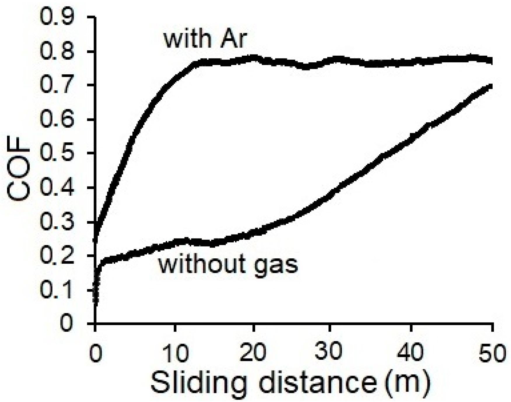
- Additional gases, such as Ar and N2, significantly increased values of HIT. COF value in the case of additional Ar increased more than twofold. Added N2 caused a marked increase of COF at a slight increase in the value of hardness HIT.
- Sample No. 6 with WC/C coating deposited with added gas Ar is the best sample according to values of hardness and COF. Its hardness is equal to 28.5 ± 2 GPa, which is 33% greater, as opposed to the coating deposited without added gas (ca. 20.9 GPa). On the other hand, the COF of the coating deposited with Ar (ca. 0.8) is more than three times greater when compared with the coating deposited without added gas (ca. 0.26). Therefore, when choosing one of these coatings, it is necessary to consider the conditions of the components′ coated surface usage.
- During deposition, Ar was built into the coating, which could have caused internal compressive pressure. That could have, in turn, caused an increase of hardness, the opposite of the coating deposited without added gas. In the case of N2, HIT may increase due to the formation of W nitrides in the coating, which has a higher HIT than W.
- The temperature of annealing in the case of added N2 and Ar caused a dramatic decrease of HIT. In the case of Ar, the measured HIT values were significantly smaller.
- In the case of added Ar, the 500 and 800 °C temperatures of annealing caused a dramatic decrease of COF, from 0.77 ± 0.02 to 0.27 ± 0.05 and 0.37 ± 0.06. In the case of added N2, the annealing temperatures caused a similar decrease in COF.
- In the process of annealing in an unprotected atmosphere at the temperatures of 500 and 800 °C, the WC/C coatings were degraded mainly due to oxidation, which was partially accompanied by swelling. WC/C coating deposited with added Ar and annealed at the temperature of 800 °C was significantly degraded due to the aforementioned mechanisms.
- It is appropriate to use N2 as an added gas, to improve the resistance against oxidation of the WC/C coating deposited using the PECVD method with W hexacarbonyl.
Author Contributions
Funding
Acknowledgments
Conflicts of Interest
References
- Bhushan, B.; Gupta, B.K. Handbook of Tribology: Materials, Coatings, and Surface Treatments; McGraw-Hill: New York, NY, USA, 1991; p. 1643. [Google Scholar]
- Makowka, M.; Pawlak, W.; Konarski, P.; Wendler, B. Hydrogen content influence on tribological properties of nc-WC/a-C:H coatings. Diam. Relat. Mater. 2016, 67, 16–25. [Google Scholar] [CrossRef]
- Lofaj, F.; Kabátová, M.; Klich, M.; Vaňa, D.; Dobrovodský, J. The comparison of structure and properties in DC magnetron sputtered and HiPIMS W-C:H coatings with different hydrogen content. Ceram. Int. 2019, 45, 9502–9514. [Google Scholar] [CrossRef]
- Horňák, P.; Kottfer, D.; Kaczmarek, L.; Kianicová, M.; Balko, J.; Rehák, F.; Pekarčíková, M.; Čižnár, P. The effect of pressure, bias voltage and annealing temperature on N2 and N2 + SiH4 doped WC/C DC magnetron sputtered layers. Ceram. Silik. 2018, 62, 97–107. [Google Scholar] [CrossRef]
- Abad, M.D.; Muñoz-Márquez, M.A.; El Mrabet, S.; Justo, A.; Sánchez-López, J.C. Tailored synthesis of nanostructured WC/a-C layers by dual magnetron sputtering. Surf. Coat. Technol. 2010, 204, 3490–3500. [Google Scholar] [CrossRef]
- Zhou, S.G.; Wang, L.; Wang, S.C.; Xue, Q. Comparative study of simplex doped nc-WC/a-C and duplex doped nc- WC/a-C(Al) nanocomposite layers. Appl. Surf. Sci. 2011, 257, 6971–6979. [Google Scholar] [CrossRef]
- Kosinskiy, M.; Ahmed, S.I.U.; Liu, Y.; Gubisch, M.; Mastylo, R.; Spiess, L.; Schaefer, J.A. Friction and wear properties of WC/C nano-scale multilayer layers on technical surfaces. Tribol. Lett. 2011, 44, 89–98. [Google Scholar] [CrossRef]
- Agudelo-Morimitsu, L.C.; DeLaRoche, J.; Escobar, D.; Ospina, R.; Restrepo-Parra, E. Substrate heating and post-annealing effect on tungsten/tungsten carbide bilayers grown by non-reactive DC magnetron sputtering. Ceram. Int. 2013, 39, 7355–7365. [Google Scholar] [CrossRef]
- El Mrabet, S.; Abad, M.D.; Sánchez-López, J.C. Identification of the wear mechanism on WC/C nanostructured coatings. Surf. Coat. Technol. 2011, 206, 1913–1920. [Google Scholar] [CrossRef]
- Novák, M.; Lofaj, F.; Hviščová, P.; Podoba, R.; Haršáni, M.; Sahul, M.; Čaplovič, Ľ. Nanohardness of DC magnetron sputtered W–C layers as a function of composition and residual stresses. Key Eng. Mater. 2015, 662, 107–110. [Google Scholar] [CrossRef]
- Park, Y.S.; Park, Y.; Jung, H.; Jung, T.H.; Lim, D.G.; Choi, W.S. Tribological properties of a-C:W film deposited by radio frequency magnetron Co-sputtering method. Thin Solid Film. 2012, 521, 107–111. [Google Scholar] [CrossRef]
- Li, Y.; Zhang, A.; Li, G. The influence of microstructure on mechanical property of polytypic TiC/WC nanomultilayers. Vacuum 2015, 117, 23–26. [Google Scholar] [CrossRef]
- Zhao, H.; Ni, Z.; Ye, F. Effect of carbon content on structure and properties of WCN coatings prepared by RF magnetron sputtering. Surf. Coat. Technol. 2016, 287, 129–137. [Google Scholar] [CrossRef]
- Hornak, P.; Kottfer, D.; Kaczmarek, L.; Kyziol, K.; Vavro, J.; Klich, M.; Trebuna, J.; Vrabel, M.; Frankova, M. Microstructure and mechanical properties of annealed WCC coatings deposited with different gas mixtures in an RFMS process. Ceram. Silikáty 2019, 63, 213–222. [Google Scholar] [CrossRef]
- Lofaj, F.; Kvetková, L.; Hviščová, P.; Gregor, M.; Ferdinandy, M. Reactive processes in the high target utilization sputtering (HiTUS) W–C based coatings. J. Eur. Ceram. Soc. 2016, 36, 3029–3040. [Google Scholar] [CrossRef]
- Gesheva, K.A.; Vlakhov, E.S.; Stoyanov, G.I.; Beshkod, G.D.; Marinov, M. Deposition CVD-tungsten and characterization of and tungsten carbonitrides on (100) Si. Ceram. Int. 1996, 22, 87–89. [Google Scholar] [CrossRef]
- Neto, M.A.; Silva, E.L.; Fernandes, A.J.S.; Oliveira, F.J.; Silva, R.F. Deposition of α-WC/a-C nanocomposite thin films by hot-filament CVD. Surf. Coat. Technol. 2011, 206, 103–106. [Google Scholar] [CrossRef]
- Gesheva, K.; Abrosimova, V.; Beshkov, G. CVD carbonyl thin films of tungsten and molybdenum and their silicides—a good alternative to CVD fluoride tungsten technology. J. Phys. IV 1991, 2, 865–871. [Google Scholar] [CrossRef]
- Sagalovych, A.; Popov, V.; Sagalovych, V.; Dudnik, S.; Popenchuk, R. Development of the chemical vapor deposition process for applying molybdenum coatings on the components in assembly and engine construction. East.Eur. J. Enterp. Technol. 2020, 2, 6–15. [Google Scholar] [CrossRef]
- Erokhin, M.N.; Kazantsev, S.P.; Chupyatov, N.N. Wear-resistance of carbide-containing chrome coatings obtained from gas phase (in Russian). Vestn. Fed. State Educ. Inst. High. Prof. Educ. Mosc. State Agroeng. Univ. Named VP Goryachkin 2017, 5, 48–53. [Google Scholar]
- Ferdinandy, M.; Lofaj, F.; Dusza, J.; Kottfer, D. Preparation of WC coatings by W(CO)6 decomposition using PE CVD method (in Slovak). Chem. Lett. 2011, 105, s442–s444. [Google Scholar]
- Lofaj, F.; Ferdinandy, M.; Cempura, G.; Horňák, P.; Vnouček, M. Transfer film in a friction contact in the nanocomposite WC-C coatings. J. Aust. Ceram. Soc. 2013, 49, 34–43. [Google Scholar]
- Lofaj, F.; Ferdinandy, M.; Kottfer, D.; Dusza, J.; Němeček, J. Tribological properties of the Cr-C and W-C based PECVD nanocomposite coatings (CD room). In Proceedings of the 11th Conference (ECERS 2009), Krakow, Poland, 20–25 June 2009; pp. 642–646. [Google Scholar]
- Ferdinandy, M.; Kottfer, D.; Hviščová, P.; Balko, J. Preparation of WCrC coatings by W(CO)6 and Cr(CO)6 decomposition using PECVD method (in Slovak). In Proceedings of the 14th Conference Layers and Coatings, Trenčianska Teplá, Slovakia, 19–20 October 2015; pp. 87–89. [Google Scholar]
- Usoltsev, I.; Eichler, R.; Wang, Y.; Even, J.; Yakushev, A.; Haba, H.; Asai, M.; Brand, H.; Di Nitto, A.; Düllmann, C.E.; et al. Decomposition studies of group 6 hexacarbonyl complexes. Part 1: Production and decomposition of Mo(CO)6 and W(CO)6. Radiochim. Acta 2015, 104, 141–151. [Google Scholar] [CrossRef]
- Rezuchina, T.N.; Švyrev, V.V. Saturated vapor pressure and sublimation temperature of Mo(CO)6 and W(CO)6 (in Russian). Vestn. Mosk. Univ. 1952, 6, 41–46. [Google Scholar]
- Garner, M.L.; Chandra, D.; Lau, K.H. Low-temperature vapor pressures of W-, Cr-, and Co-carbonyls. J. Phase Equilibria 1995, 16, 24–29. [Google Scholar] [CrossRef]
- Chellappa, R.; Chandra, D. Assessment of vapor pressure data of solid metal carbonyls. J. Chem. Thermodyn. 2005, 37, 377–387. [Google Scholar] [CrossRef]
- Toby, B.H. CMPR—A powder diffraction toolkit. J. Appl. Crystallogr. 2005, 38, 1040–1041. [Google Scholar] [CrossRef]
- Lofaj, F.; Kaganovskii, Y.S. Kinetics of WC–Co oxidation accompanied by swelling. J. Mater. Sci. 1995, 30, 1811–1817. [Google Scholar] [CrossRef]
- Choy, K.L. Chemical vapour deposition of coatings. Prog. Mater. Sci. 2003, 48, 57–170. [Google Scholar] [CrossRef]


| Sample No. | Pressure (Pa) | Bias (−kV) | Current Density (mA.cm−2) | HIT (GPa) | EIT (GPa) | COF (−) |
|---|---|---|---|---|---|---|
| 1 | 2.0 | 5 | 0.8 | 14.2 | 180 | − |
| 2 | 3.0 | 16.7 | 294.5 | − | ||
| 3 | 1.0 | 1.0 | 17.5 | 305 | 0.8 | |
| 4 | 2.0 | 17.3 | 292 | 0.25 | ||
| 5 | 3.0 | 20.9 | 298 | 0.26 |
| Sample No. | Added Gas | Total Pressure (Pa) | Gas Pressure (Pa) | HIT (GPa) | EIT (GPa) | COF (−) |
|---|---|---|---|---|---|---|
| 6 | Ar | 2.0 | 1.0 | 28.5 ± 2 | 351 ± 28 | 0.8 |
| 7 | N2 | 4.0 | 2.0 | 19.7 ± 4.1 | 292 ± 17 | 0.59 |
© 2020 by the authors. Licensee MDPI, Basel, Switzerland. This article is an open access article distributed under the terms and conditions of the Creative Commons Attribution (CC BY) license (http://creativecommons.org/licenses/by/4.0/).
Share and Cite
Horňák, P.; Kottfer, D.; Kyzioł, K.; Trebuňová, M.; Majerníková, J.; Kaczmarek, Ł.; Trebuňa, J.; Hašuľ, J.; Paľo, M. Microstructure and Mechanical Properties of Annealed WC/C PECVD Coatings Deposited Using Hexacarbonyl of W with Different Gases. Materials 2020, 13, 3576. https://doi.org/10.3390/ma13163576
Horňák P, Kottfer D, Kyzioł K, Trebuňová M, Majerníková J, Kaczmarek Ł, Trebuňa J, Hašuľ J, Paľo M. Microstructure and Mechanical Properties of Annealed WC/C PECVD Coatings Deposited Using Hexacarbonyl of W with Different Gases. Materials. 2020; 13(16):3576. https://doi.org/10.3390/ma13163576
Chicago/Turabian StyleHorňák, Peter, Daniel Kottfer, Karol Kyzioł, Marianna Trebuňová, Janka Majerníková, Łukasz Kaczmarek, Jozef Trebuňa, Ján Hašuľ, and Miroslav Paľo. 2020. "Microstructure and Mechanical Properties of Annealed WC/C PECVD Coatings Deposited Using Hexacarbonyl of W with Different Gases" Materials 13, no. 16: 3576. https://doi.org/10.3390/ma13163576
APA StyleHorňák, P., Kottfer, D., Kyzioł, K., Trebuňová, M., Majerníková, J., Kaczmarek, Ł., Trebuňa, J., Hašuľ, J., & Paľo, M. (2020). Microstructure and Mechanical Properties of Annealed WC/C PECVD Coatings Deposited Using Hexacarbonyl of W with Different Gases. Materials, 13(16), 3576. https://doi.org/10.3390/ma13163576