Review

Atmospheric Pressure Plasma Deposition of TiO2: A Review

1
Radiation Laboratory, University of Notre Dame, Notre Dame, IN 46556, USA
2
Department of Physics, University of Notre Dame, Notre Dame, IN 46556, USA
*
Author to whom correspondence should be addressed.
Materials 2020, 13(13), 2931; https://doi.org/10.3390/ma13132931
Submission received: 4 June 2020 / Revised: 22 June 2020 / Accepted: 26 June 2020 / Published: 30 June 2020
(This article belongs to the Special Issue Atmospheric Pressure Plasmas in Material Science)

Abstract

:
Atmospheric pressure plasma (APP) deposition techniques are useful today because of their simplicity and their time and cost savings, particularly for growth of oxide films. Among the oxide materials, titanium dioxide (TiO2) has a wide range of applications in electronics, solar cells, and photocatalysis, which has made it an extremely popular research topic for decades. Here, we provide an overview of non-thermal APP deposition techniques for TiO2 thin film, some historical background, and some very recent findings and developments. First, we define non-thermal plasma, and then we describe the advantages of APP deposition. In addition, we explain the importance of TiO2 and then describe briefly the three deposition techniques used to date. We also compare the structural, electronic, and optical properties of TiO2 films deposited by different APP methods. Lastly, we examine the status of current research related to the effects of such deposition parameters as plasma power, feed gas, bias voltage, gas flow rate, and substrate temperature on the deposition rate, crystal phase, and other film properties. The examples given cover the most common APP deposition techniques for TiO2 growth to understand their advantages for specific applications. In addition, we discuss the important challenges that APP deposition is facing in this rapidly growing field.

1. Introduction

Plasma is defined as fully or partially ionized gas with many unique properties attributable to the long-range electromagnetic interaction between charged species. It consists of electrons, excited heavy species such as ions and neutrals, electromagnetic radiation (i.e., photons), and electromagnetic fields. Further, plasma possesses a quasi-neutral property, one of the unique properties of plasma as a state of the matter, which means that it is electrically neutral with approximately equal numbers of positively and negatively charged species. Plasma is classified into two groups based on temperature and equilibrium conditions: (1) thermal or equilibrium plasma, and (2) non-thermal or non-equilibrium plasma [1]. A thermal plasma is characterized by a high level of ionization, and all charged species achieve thermal equilibrium at a high temperature (~104 K), while a non-thermal plasma, also referred to as a cold plasma, is characterized by weak ionization, and the electrons are not in thermal equilibrium with heavy species. Therefore, the gas temperature in cold plasma is equivalent to room temperature or slightly above, and ranges from approximately ~40 °C to ~150 °C. The electron density of cold plasma is typically less than 1019 m−3 [2]. Non-thermal plasmas can be generated at both low pressure and atmospheric pressure. Overall, the temperature of each plasma species is usually defined based on the average kinetic energy of the individual species:
T i = 2 3 K B E i ,   i = 1 ,   2 ,   3 ,  
in which KB is the Boltzmann constant, Ei is the kinetic energy of an individual species (i) in thermal motion, and the angular brackets denote averaging over the entire number of species. In plasma physics, such temperatures are commonly measured in electron volts: 1 eV ≃ 11600 K [3]. For more detailed information on weakly ionized plasmas, we refer the reader to the most recent review article that covers their basic principles and applications [4].
Thermal (equilibrium) plasmas have been used for material processing for more than 100 years. One common example of thermal plasma in material processing is electric welding. In general, most of the electrical power used to ignite plasma is converted into heat, and, therefore, thermal plasmas can melt metallic surfaces as well as the electrodes used to ignite the plasma. However, it is undesirable to have such excessive heat in contact with the heat-sensitive or softer surfaces used in material processing, such as coating, cleaning, and etching. For these applications, cold plasmas may be a good alternative, as the electrons have high thermal energy, while the heavier species remain “cold”. Thus far, large-scale industrial technology is generally based on non-thermal plasmas ignited at reduced or low gas pressures, in which the neutral gas temperature is low enough to prevent damage to processing materials. There is also a long history of using non-thermal (non-equilibrium) plasmas in material processing; however, using atmospheric pressure plasmas (APPs) to do so is recent. This novel approach to material processing is appealing because of the combination of simplicity, low cost, and the wide range of possibilities for surface treatment and modification [5,6]. Therefore, there has been a rapidly growing interest in recent years in replacing a low-pressure plasma with a cold atmospheric plasma, as expensive vacuum equipment can be eliminated. Currently, there are several methods to generate APPs from microwave or radio frequency (rf) discharge, dielectric barrier discharge (DBD), and direct current glow discharge [5,7]. These methods use various gases or gas mixtures as a feed gas and have unique features that are suitable for numerous applications. For example, a process of plasma-enhanced/assisted chemical vapor deposition (PECVD/PACVD; here we will use the PECVD term hereafter) at atmospheric pressure can be optimized by using a mixture of various gases as well as a gas/liquid precursor in the feed gas to enhance plasma chemistry [8]. The scientific and industrial communities recognize the advantage of using APP already because of rich plasma chemistry, which plays a significant role in material processing techniques, such as PECVD, plasma-assisted etching, and plasma polymerization [1,9,10,11,12]. Plasma can effectively deliver reactive chemical species that promote surface reactions that would otherwise require a high substrate temperature. Thus, APPs are efficient sources to achieve a high deposition rate of thin film at a low substrate temperature, which prevents any thermal damage or other side effects related to heating [6]. Lower substrate temperatures in PECVD are important in electronic applications in which a film is deposited onto device structures with low thermal budgets, particularly in those in which substrates are sensitive to high surface temperatures, such as polymers or organic compounds. Defect-free and strongly adherent thin film deposited over microscopic features is essential in manufacturing microelectronic devices because device structures are sensitive to temperature. Thus, due to the non-equilibrium nature of non-thermal plasmas, films can be deposited at low temperatures with a chemical composition and crystalline morphology that would be unattainable under higher-temperature equilibrium conditions [13].

2. Advantages of Atmospheric Pressure Plasma-Enhanced Deposition

APP discharge is not only a relatively novel and versatile technique but is also an emerging tool in cost-effective solutions for many processing challenges in material sciences. Compared to compact deposition methods under vacuum conditions, APP-based deposition is a more robust technology that allows thin films to be deposited on substrates with various sizes regardless of their geometry [7]. Plasma-enhanced deposition techniques offer the benefit of minimal chemical waste throughout the process and are solvent-free compared to other methods, such as the sol-gel process. Moreover, APP deposition features relatively high deposition rates; however, its efficacy in achieving high deposition rates of coating depends upon numerous parameters, including optimal gas flow rates, concentrations of reactive species, plasma power, and precursors, as well as the type of deposition method used [7]. One of the best APP deposition methods that uses precursors and offers a significant rate of deposition is injection plasma processing [14]. Precursors, in the form of powder or volatile molecules, are introduced downstream of the plasma discharge, where they are vaporized and then interact with reactive species in the plasma discharge. The interaction of precursor molecules with highly reactive species in plasma lowers the activation energy required for deposition. As a result, deposition is achieved when the resulting mixture is sprayed onto the substrate, and the rate of deposition achieved by this method is usually on the order of 10 µm/min.
In the case of titanium dioxide or titania (TiO2) deposition by an injection method, several works [15,16,17,18] have reported the use of different TiO2 solution precursors, but, in numerous studies, Ti-based compounds were used as precursors, among which the most widely used compound is titanium tetraisopropoxide (Ti[OCH(CH3)2]4, TTIP). Other precursors used commonly are titanium tetrachloride (TiCl4), titanium ethoxide (Ti4(OCH2CH3)16, Ti(OEt)4, TEOT), and titanium bis(acetylacetonate) diisopropoxide ([(CH3)2CHO]2Ti(C5H7O2)2, TIPO). However, contrary to other precursors, the former produces toxic by-products and chlorine contamination, and, therefore, is now used less frequently, while the two latter precursors, TEOT and TIPO, possess some advantages, such as low carbon content and relatively high resistance to water, respectively. It has been found that deposition rates using these precursors can even range from 20 to 40 µm/s [16], which is significantly higher than those obtained in traditional deposition techniques. Typically, deposition rates for conventional deposition techniques range on the order of nm/min [19]. For example, the deposition rate of TiO2 films using PECVD is in the range of 1 µm/min, which is roughly three orders of magnitude greater than conventional deposition methods [20].
Moreover, to achieve effective and efficient photocatalytic TiO2 coating, it is imperative to prevent the anatase phase from transforming to rutile. Research has shown that the anatase-to-rutile phase ratio may be tuned by varying the parameters, e.g., the arc current in plasma [21]. Studies have also reported that the transition from the anatase to rutile phase can be controlled and delayed at high temperatures for TiO2 deposited employing injection plasma processing [16].
Another study showed that APP-based deposition of anatase TiO2 nanoparticles can be fabricated on a flexible, transparent plastic substrate to produce dye-sensitized solar cells (DSSCs) at low temperature (190 °C) [22]. Moreover, it has been demonstrated that this methodology can be scaled up to treat large areas (up to several meters), and, thus, it can be considered compatible with high-throughput, roll-to-roll manufacturing [22]; see Figure 1.
Specific descriptions of APP benefits are presented below for the specific methodologies, including PECVD, plasma-enhanced atomic layer deposition (PEALD), and atmospheric pressure dielectric barrier discharge deposition (APDBDD).

3. Importance of TiO2

Thin-film capacitors, antireflection coatings, optical waveguides, photo-electrochemical (PEC) cells, sensors, and mechanical or corrosion-resistant barriers are some selected applications of TiO2. Further, because of miniaturization in data-storage technology, the thickness of the oxide layer of dynamic random-access memory (DRAM) needs to be reduced, which will then, in turn, limit the use of silicon dioxide or silica (SiO2). Research has demonstrated that there is an abrupt increase in leakage current if SiO2 is thinner than 1.5 nm [23]. This is attributable to the low dielectric constants of SiO2 (~3.8), and, therefore, materials with a higher dielectric constant are required to replace silica. Highly dielectric materials, such as tantalum oxide (Ta2O3), aluminum oxide (Al2O3), yttrium oxide (Y2O3), barium/strontium titanate (Ba/Sr)TiO3, lead zirconate titanate (Pb(Zr,Ti)O3), and TiO2 have been studied for the past decade in search of a material with a low leakage current and closed packing density. Among these oxides, TiO2 stands out because of its high dielectric constant (i.e., 30–100) as well as its good thermal stability and sufficient barrier height.
In addition to the generic high dielectric property of TiO2, it can be used in photocatalysis, and has a high hydrophilicity and water splitting capability. These properties are related to different amounts of crystalline phases present in the deposited layer [24]. Therefore, depending on the material structure, TiO2 can be exploited for different applications related to energy conversion and catalysis.
Generally, TiO2 can be found in three crystalline allotropes: anatase, rutile, and brookite. The formation of these different crystal phases depends on the preparation methods, temperature, deposition parameters, types of substrate, and doping [24,25]. For example, TiO2 in the anatase crystalline phase, which is an excellent photocatalytic material, converts to rutile if annealed at higher temperatures. It is generally accepted that the pure anatase phase displays a higher photocatalytic activity compared to rutile TiO2 as was also supported theoretically by the exciton transport model [26]. High activity and the non-toxic properties of anatase TiO2, together with its exceptionally high chemical stability, make this compound ideal as a protective layer in PEC cells [27].
Lastly, anatase TiO2 can be a suitable material for photo-assisted water splitting in a solar cell upon exposure to light with energy greater than the TiO2 band gap (i.e., 3.26 eV) [28]. It is generally accepted that the formation of charge carriers by photon absorption initiates the redox reactions at the surface [29]. Photons with sufficient energy can create an electron–hole pair, and, as a result, the excited electron in the conduction band reduces oxygen to superoxide, while the hole in the valence band oxidizes water molecules to hydroxyl ions [30]. Moreover, titania has high durability as well as chemical activity and stability under ultraviolet (UV) light [31,32], which, in addition to its water splitting ability, makes it useful for antimicrobial treatment, water purification, self-cleaning purposes [33,34,35,36], and material passivation [37]. The species formed through redox reactions at the surface are sufficiently powerful to decompose organic molecules or microbes, leading to the self-cleaning ability of TiO2. Consequently, there is the disadvantage of a wide band gap in TiO2, as it cannot be used in solar cells for visible light. To overcome this issue, the study of titanium oxide band gap engineering by doping with metallic or non-metallic atoms has been initiated [38]. For example, research has found that nitrogen doping can improve visible-light photoactivity by reducing the band gap [39]. Thus, in recent years, more studies have focused on using APPs to deposit nitrogen-doped thin films: titanium oxynitride (TiOxNy) [40,41] and N–doped TiOx [42,43].
Many important studies have been conducted on the properties of TiO2 thin films and nanostructures that make this material versatile for many different applications. We refer the reader to review articles published within the last year that have summarized work on TiO2 characterization and applications in energy- and environment-related processes [44,45,46,47].

4. Atmospheric Pressure Plasma-Enhanced Deposition Methods

This review focuses mainly on the use of APP-enhanced deposition methods for TiO2 films. However, some pioneering works are also reported and are followed by current research findings using plasma deposition methods, such as PECVD, PEALD and APDBDD, including deposition by atmospheric pressure plasma jet (APPJ). These methods have been also employed to deposit TiO2 using APP; among them, the PECVD technique is used most commonly [48]. The wide use of this technique is attributable to its many advantages, primarily its relatively simple and low-cost experimental set-up and its ability to deposit thin films even at low temperatures [49,50,51,52,53,54,55,56,57]. The general process of the PECVD technique to deposit TiO2 employs a Ti-based precursor—TTIP is used most often—which is transferred by a carrier gas, typically an inert gas, and then mixed with a feed gas. Thereafter, this mixture is passed through the plasma-generating region (also referred to as the discharge region), where reactive species are formed from the feed gas and precursor. These species are then directed to be deposited on the desired substrate. An example of a PECVD set-up used by Yoshiki et al. is shown in Figure 2 [49]. The authors used TTIP as the Ti precursor carried by He, which was mixed with O2 (primary feed gas) before passing to a discharge region [49]. In this method, plasma is generated within a quartz tube between parallel electrodes kept outside the tube and TiO2 is deposited on the inner wall of the tube.
In addition to a variety of experimental set-ups, deposition parameters such as the plasma power, flow rate, substrate temperature, and annealing temperature vary in different studies that have used PECVD. Different types of discharges have been also applied. However, most researchers have used either an rf of 13.56 MHz [50,52,53,54,56] or microwave discharges [49,51,55,58,59,60,61] to ignite the plasma. Further, the thickness, morphology, crystallinity, and other properties of the grown films have been diverse in research findings as they depend largely on the deposition parameters.
Although DBD-based techniques [62,63,64,65] are not as popular as PECVD, they have been used to deposit TiO2 in several studies to date. In the DBD technique, a dielectric material is used as a barrier between high-voltage electrodes, which prevents arcing during the plasma discharge at atmospheric pressure. For this type of plasma ignition, most researchers have used a power supply that generates a plasma frequency in the range of kHz rather than MHz. The use of DBD methods for thin film deposition is discussed more extensively in two of Fanelli et al.’s review articles [13,66].
In the PEALD method, thin films are grown at a very low deposition rate per cycle, which results in a thickness comparable to the atomic layer thickness [67,68]. However, the precursor and plasma gas are supplied intermittently in the form of pulses in PEALD, unlike in other deposition techniques, in which they are supplied simultaneously in a continuous mode. The deposition of films is obtained in cycles, in which each cycle is divided into multiple pulses, beginning with the precursor pulse (i.e., when a precursor is fed) and reactant pulse (i.e., when plasma gas is fed as well as when plasma is generated). The purging gas is then fed during the purge pulse, which is generated after each precursor and reactant pulse. Moreover, TiO2 films can be alternated and compositionally controlled by introduction of other materials in a so-called supercycle. In a previous PEALD study, a typical cycle was used to deposit TiO2 thin films, while Al-doped TiO2 thin films were deposited in a supercycle, which was made up of a number of cycles of Ti precursor followed by one cycle of Al precursor [68]. Recently, a supercycle process was used to selectively deposit TiO2 on defined regions over substrates by intercalation of plasma etching cycles in PEALD [69]. In this approach, three steps were performed as is presented in Figure 3.
In another deposition method, Yuji et al. [70] and Ha et al. [71] used a plasma torch to deposit TiO2, where the discharge was created between an anode and a cathode that consisted of a Ti rod to produce plasma in the form of a jet. Moreover, Fakhouri et al. [16] and Jimenez et al. [72] used completely different set-ups to introduce the precursor in the post-discharge zone. Fakhouri et al. sprayed the precursor liquid directly into an open-air APPJ, while Jimenez et al. mixed precursor vapor with a carrier gas before introducing the precursor into the post-discharge zone.
Technical aspects of the APP deposition methods largely vary across research groups because these technologies are still in the development stage and the majority of them are based on lab-built instrumentation; thus, they are only briefly described above.

5. Atmospheric Pressure Plasma-Enhanced Deposition of TiO2

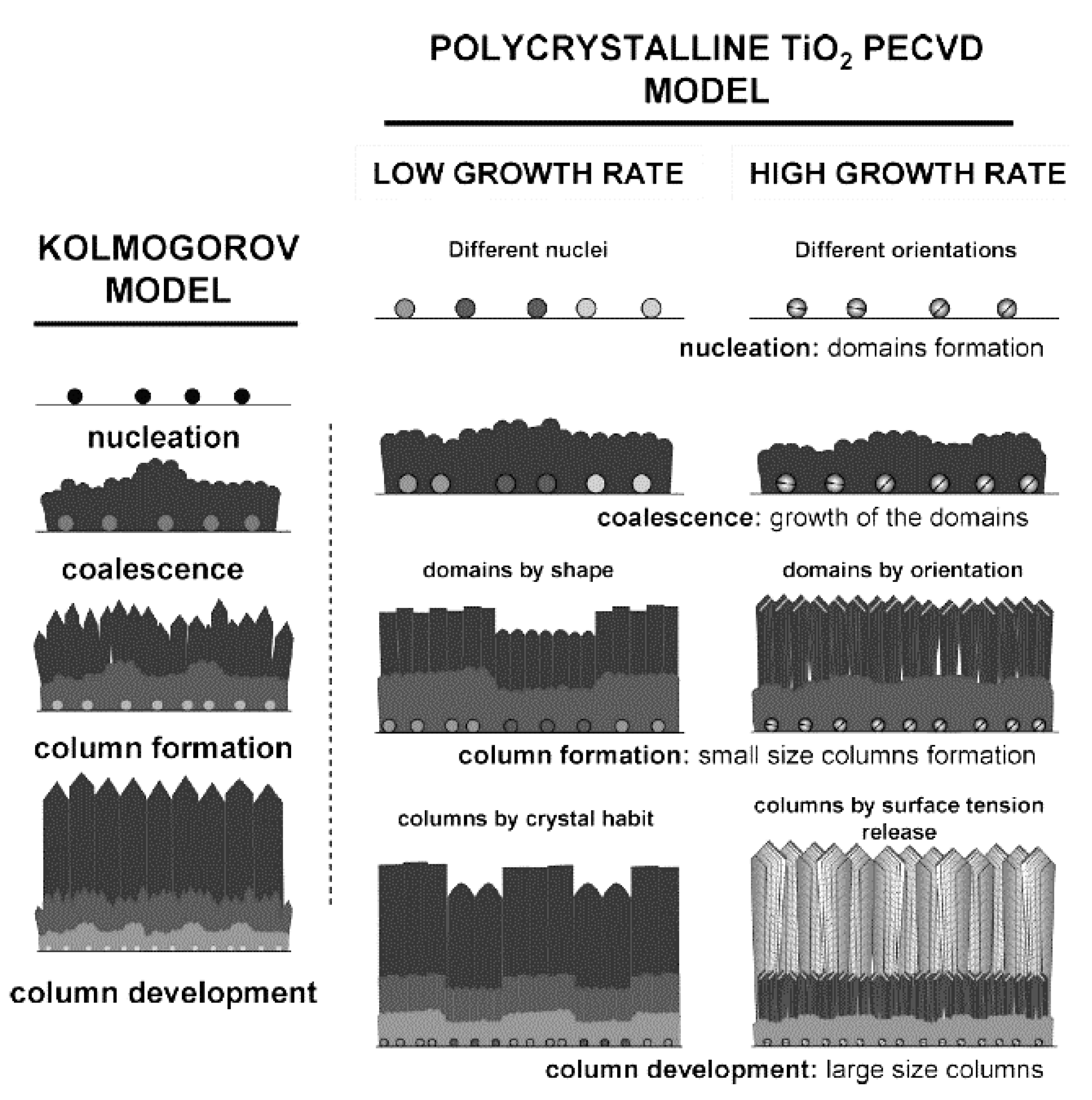
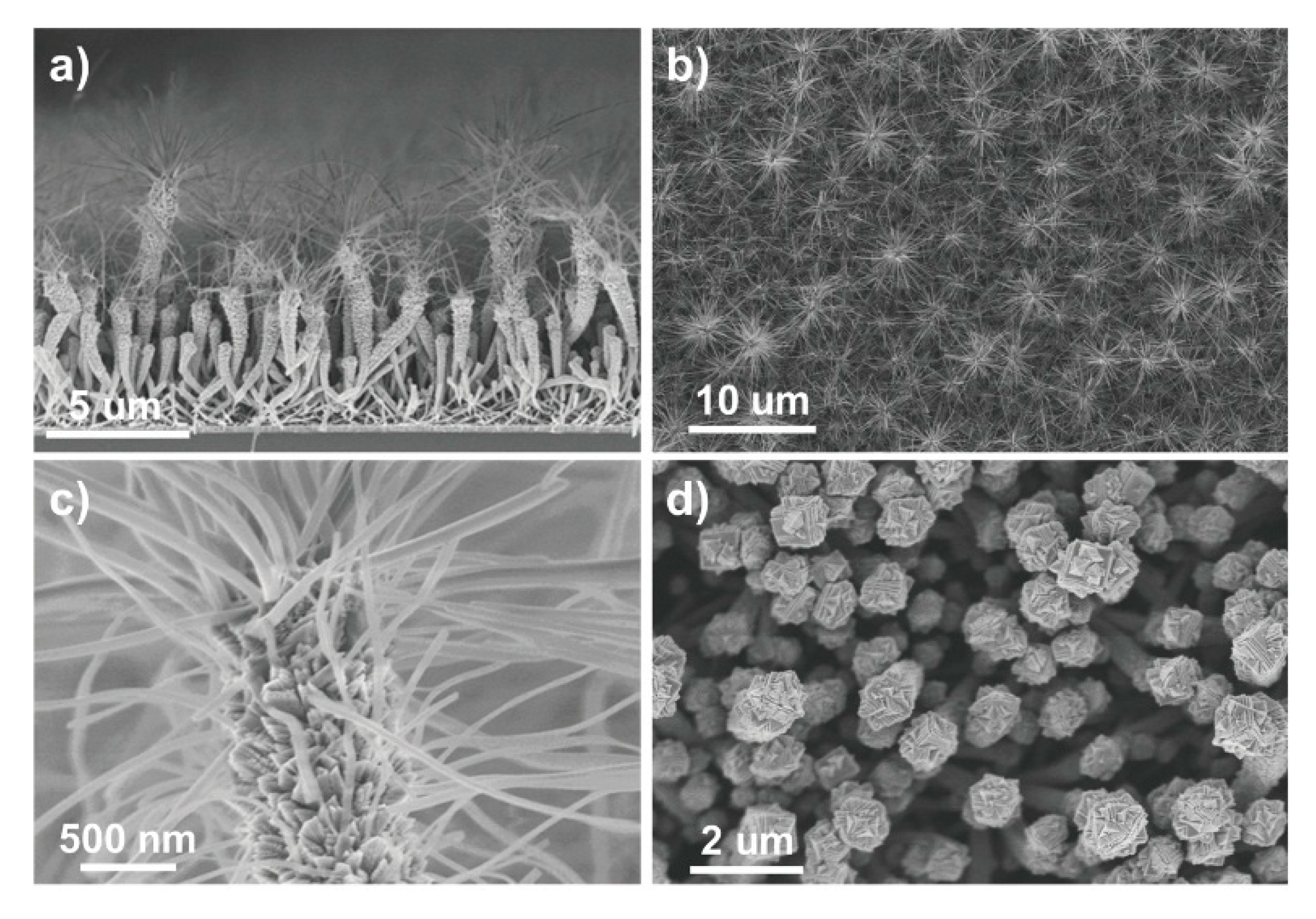
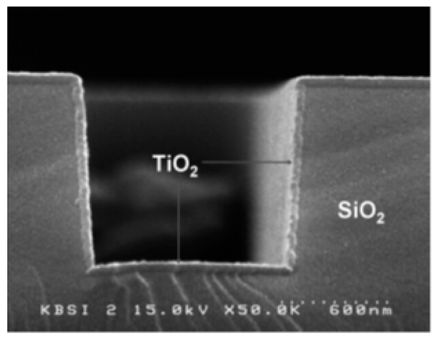
5.1. Plasma-Enhanced Chemical Vapor Deposition

Plasma deposition of TiO2 dates back to the 1960s, but only in the early 1980s, Williams and Hess [73] investigated the structural properties of TiO2 films grown from TiCl4 and O2 mixtures and the correlation between crystalline TiO2 phases and plasma variables. Their research showed significant phase changes in a deposited TiO2 film, from the amorphous to anatase phase and then to rutile, with an increasing post-deposition annealing temperature that ranged from 300 °C to 600 °C. A year later, the authors explored and produced high-quality TiO2 photoanodes on a polycrystalline Ti substrate grown at several different rf powers during PECVD [74]. They observed that, as the rf power increased, the relative quantum efficiencies of the films decreased. More importantly, compared to films grown thermally, the research findings revealed higher quantum efficiency below a wavelength of 330 nm. These superior PEC properties were attributed to better crystalline (in this case the rutile TiO2 phase) quality of the film and smaller amounts of chlorine incorporated. Thus, this finding indicated that particular chemical reactions attainable only by plasma deposition, not conventional methods, can enhance certain PEC properties of a thin film.
In the early 1990s, to avoid chlorine-related hazards from the TiCl4 precursor and to counter chlorine contamination, metalorganic compounds, such as TTIP, TEOT, Ti(O-i-C3H7)4, and Ti(OCH(CH3)2)4, were used to grow TiO2 films. Further, these precursors allowed the surface quality to be improved. For example, a mixture of Ar (or other inert gases) and TTIP was used to deposit an amorphous, carbon-free, scratch-resistant TiO2 film on Si wafers or glass using PECVD [57]. In this study, the stoichiometry of the deposited TiO2 was independent of the gas phase parameters and the substrate temperature, although the film density, which is correlated with the refractive index and stability, varied with the gas phase parameters and substrate temperature during and after deposition. Further, Lee et al. performed a thorough investigation of the structure, chemical composition, and optical and electrical properties of amorphous TiO2 deposited on clean Si(100) using TTIP as a precursor, and found that two parameters, i.e., the deposition rate and refractive index of the TiO2 thin film, changed with varying rf power, gas pressure, and substrate temperature [56]. However, both parameters remained the same for various oxygen flow rates, although spectroscopic studies confirmed the presence of contamination derived from carbonaceous compounds and water. A depth profile indicated that the films prepared under optimal conditions were homogeneous, with an O:Ti ratio of 2, and that carbonaceous contamination decreased gradually with depth. Moreover, a partially crystalline film could be obtained at lower temperatures when the deposition time was long enough to allow the deposited atoms to be displaced sufficiently to form a crystal. Even so, the longer deposition time increased the surface roughness because of a small crystallite growth. It is worth noting that, previously, the deposition time required several hours [56], while the current plasma methods operate with a substantially reduced deposition time (for example, see Figure 4) [75]. While the TiO2 film deposited in Lee et al.’s study exhibited a small capacitance−voltage hysteresis, the dielectric constant increased after the film was treated with N2 and O2 plasma. Overall, the post-deposition plasma treatment of the film by O2 improved the quality of the TiO2–Si interface by reducing the oxygen vacancies and defects [56]. Later, in the early half of the 2000s, the advantages of PECVD were reinforced when Maiti et al. investigated TiO2 thin films deposited on strained Si–Ge layers and strained Si layers with interfacial traps [55,60]. In both of their works, they used TTIP with oxygen in their microwave discharge system for low-temperature deposition. The x-ray diffraction (XRD) results demonstrated that a longer plasma deposition time led the fully amorphous phase to convert to partially crystalline films at a low substrate temperature. In general, such a conversion was observed either when the substrate temperature increased and/or when the layer deposited was thicker. Both of these factors are known to help form crystal structures.
Studies published in 2019 compared the effects of rf APP with thermal treatment on crystallization of amorphous TiO2 films [76] and also reported the effect of plasma synergy with substrate temperature [77]. The study showed that the plasma improved the crystallization significantly, and the phase transition to the anatase film was observed at a lower temperature and in a shorter time [76]. However, some undesired etching also occurred, during which some material was removed [76].
In PECVD, other factors, such as plasma reactive species (e.g., ions), rather than temperature alone, can contribute to the formation of films with different crystalline morphologies. The correlation between plasma species generated in the discharge and the elemental composition of the deposited films is explored often [78]. One of the most common plasma diagnostic methods to identify plasma species is OES, which detects light emitted from excited plasma species and can provide certain useful information, such as plasma species density and their energy distribution, and help interpret the growth mechanism. The presence of specific ions created in plasma in the PECVD technique promotes precursor dissociation at the surface and thus makes deposition possible at a lower temperature compared to conventional deposition techniques [78]. Since PECVD was introduced, much research has been dedicated to understanding the role of plasma-reactive species in TiO2 film growth [12].
For example, in early studies, Lee investigated the role of energetic ions in plasma-enhanced deposition [59] and explained that ions are responsible for both etching and the increased density of the deposited film. Due to the densification of the deposited TiO2 film in rf-biased PECVD, the anatase phase dominated over the rutile phase below 400 °C, while the rutile phase became dominant at a higher annealing temperature. An interesting comparison between low-pressure chemical vapor deposition (LP-CVD) and PECVD-grown films revealed that PECVD produces a smoother, denser, and more continuous TiO2 layer than does LPCVD [79]. However, in contrast to LPCVD, two effects, i.e., a lower deposition rate and poor crystallinity, were drawbacks of PECVD in this particular study. These effects were attributed to the ion bombardment and high fragmentation of the precursor during the process, which hindered the Ti–O bond formation.
Another study, which investigated the mechanism of TiO2 deposition using the PECVD method, revealed that H and OH radicals in an H2/O2 mixture played a key role in this process [80]. The contribution of both radicals was confirmed by a comparative study in which only an O2 gas plasma was used. The deposition rate for the O2 gas plasma, in which O radicals were produced, was insignificant compared to that for the H2/O2 mixture. Moreover, the authors observed that the deposition rate was strongly correlated to the ratio of both radical densities, with the maximum deposition rate reached at 80% H2 [80]. Thus, it was concluded that two competitive factors affected the deposition rate and film morphology in low-temperature deposition: dissociation and activation of precursor molecules by H radicals and deactivation of precursor molecules by OH radicals. Although mixing O2 in the feed gas enhanced the H radical density in the plasma, a high deposition rate could only be achieved by optimizing the gas phase parameters (i.e., gas composition and flow rate) and plasma power. This study also confirmed previous research findings which emphasized the contribution of H2 gas admixture in open-air PECVD used to deposit highly dielectric amorphous films [71]. In the absence of annealing, there was no crystallization in the film grown by PECVD because of the structural defects and vacancies on the surface. Interestingly, the substrate temperature had no significant effect on the deposition rate in this study. However, increasing the substrate temperature decreased the content of OH groups in the film and increased Ti−O−Ti bond formation, thus resulting in a high refractive index and small band gap in the deposited material. Moreover, research has found that efficient fragmentation of precursor molecules on the surface caused lower carbonaceous contamination in PECVD-grown films compared to those grown using LPCVD [81]. Note that the carbon content increased with increasing plasma power. Nonetheless, LPCVD produced a partial anatase phase at a substrate temperature of approximately 350 °C, while the thin film produced by PECVD had to be annealed under ambient pressure at 400 °C to obtain an anatase crystal. This observation indicated that the PECVD film had a considerable number of defects and oxygen vacancies initially, which hindered the crystallinity. However, PECVD film was smoother and highly conformal, exhibiting dense microstructures [82].
A further comparison of PECVD and LPCVD showed that the former exhibited a faster deposition rate, which might result from a reduced activation energy barrier, as was mentioned above [54], and a lower O2 concentration and rf power. A higher O2 concentration led to a high density of atomic oxygen, which then oxidized the precursor molecules before deposition, rendered them inactive, and hence resulted in a low deposition rate. Atmospheric pressure chemical vapor deposition without plasma also led to a much lower deposition rate compared to PECVD when similar experimental set-ups were used for both techniques, and thus makes PECVD attractive for its potential application in industry [83]. A recent study that used APP to coat polymer optical fibers with photocatalytic anatase TiO2 thin films showed greater advantages of this method than other commonly used techniques, such as thermal CVD and wet chemical processes in functional coatings [84].
As mentioned above, in studies that used PECVD, precursor dissociation by reactive oxygen led to a very high deposition rate and crystallinity at lower temperatures compared to conventional deposition techniques [85]. However, this method may sometimes lead to less dense grains and, eventually, poor crystallinity in the deposited thin film compared to LPCVD. To improve the crystallinity, Yamauchi and Imai reported the growth of TiO2 films in the form of nanosized columnar grains using TTIP in PECVD [52]. The authors also investigated the effect of deposition parameters on the photoinduced hydrophilicity of the deposited film [52], as hydrophilic TiO2 can be a very efficient self-cleaning surface [86]. Further, their study showed that the film, which grew at 340 °C, exhibited high hydrophilicity, which increased with increasing temperature up to 380 °C in the absence of UV irradiation and became super-hydrophilic after 5 minutes of UV irradiation [52]. Similarly, super-hydrophilicity and excellent photocatalytic activities were observed for TiO2 films grown by post-discharge of rf atmospheric plasmas supplied with oxygen and argon [75].
Another approach to obtain a smooth crystalline TiO2 film is to use APP with pulsed injection metalorganic chemical vapor deposition. Jiménez et al. used this method and obtained smooth (i.e., average roughness of 1 nm) titania films on a Si substrate using different deposition parameters [72]. In their study, the deposited film crystalized at 275 °C and higher temperatures. In addition, an increase in deposition temperature removed contamination. Jiménez et al. found that the deposition rate also increased with an increased concentration of Ti precursor in plasma at a particular temperature, but, on the other hand, a lower precursor concentration enhanced the crystallization of the film. Battiston et al. compared the properties of amorphous TiO2 deposited with and without oxygen present in nitrogen and argon plasmas [87]. Films prepared in oxygen-free plasmas at low temperatures were smooth, transparent, and highly resistive but had a low conductivity, which increased at higher temperatures. Recently, it was also confirmed that improved transparency to visible light can be achieved when the roughness of TiO2 films is reduced [32], while films prepared in the presence of oxygen were rougher and had little optical absorbance but showed high efficiency in photocurrent generation [87].
At the same time that important factors involved in the deposition rate and crystallinity of TiO2 films have been explored, several film growth models have been proposed. In general, the growth process of TiO2 in PECVD follows a Kolmogorov model, which has four stages: nucleation, coalescence, column formation, and column development (see Figure 5). In the case of a slow deposition rate, the film is controlled by the materials supplied by plasma and formed through crystal habits, while, for faster growth, steps and facets are formed that release the tension [58]. A study also revealed an additional feature of anatase crystal growth in PECVD: the formation of microstructure domains that the nucleation stage potentially controls. Experimentally, low-temperature (150 °C) PECVD was used to grow micro-columnar, porous TiO2 anatase thin films on Si or glass substrates from TTIP [88]. Such a columnar morphology of thin films is beneficial for photocatalytic applications, particularly for membranes in which a high specific surface area and permeability are required.
Gazal et al. proposed another growth model for TiO2 deposition with PECVD and a microwave plasma torch [51]. They found that the reactive species differed at the center and circumference of the deposition area because of a temperature gradient from the center to the periphery of the plasma torch. In the central zone of the deposition area, the mechanism of TiO2 thin film growth followed the Kolmogorov model, which resulted in a film with a crystalline, columnar structure (see Figure 6A). In the peripheral zone, a cauliflower-like, amorphous structure formed that was a result of the agglomeration of titania nanoparticles formed in the plasma (see Figure 6B). Any temperature changes in these two areas resulted in different diffusion rates, which, in turn, altered the deposition process. The cauliflower-like assembly was observed when PECVD was used to prepare TiO2 on various substrates [89,90]. In contrast to studies in which the columnar morphology was observed [88], a plasma jet was incorporated into the experimental set-up in these studies, although both growth processes were carried out at low temperatures. Therefore, the authors concluded that the cauliflower-like structures were grown from deposited TiO2 particles produced by the titanium and oxygen reactive species that formed and collided with each other along the plasma jet [89].
An experimental study carried out in 2019 used PECVD combined with APPJ technology to elucidate the potential growth mechanisms of TiO2 thin films deposited over areas of several square centimeters [91]. In this study, the substrate’s ability to move allowed the column growth mechanism to be controlled in two modes: static and dynamic. The authors showed that, in contrast to static deposition, the movement of the substrate and a fast precursor flow led to the cauliflower-like morphology, while a low precursor flow promoted surface reactions and led to columnar TiO2 anatase thin films [91].
Recently, in parallel to work on the basic principles of film growth, more applied studies have also been carried out that have focused on increasing the photocatalytic efficiency of TiO2 films produced using PECVD. For example, Wang et al. revealed that mesoporous material, which is suitable for organic compound adsorption, could be coated with mixed anatase and rutile phases (with a phase ratio of ~55 and 45, respectively) of TiO2. This system showed up to 40% photocatalytic efficiency under fluorescent light, which the authors attributed to semiconductor–semiconductor coupling [53]. However, the efficiency under UV light differed. In addition, PECVD was used to coat microporous ceramic supports with nanocrystal anatase films to form composite membranes with photocatalytic activities comparable with those obtained from membranes prepared by the sol-gel process [92]. The authors mentioned that it might be unsuitable to use this method for polymer membranes because of the particular experimental conditions used for this deposition [92], but, later, another group that used a different set-up of APP at low temperature was able to deposit anatase films on polymer optical fiber [84].
Di et al. tested the photocatalytic properties of “as-deposited” and thermally treated TiO2 film produced by PECVD at atmospheric pressure [65]. Thermally treated TiO2 in air (calcination) exhibited better photocatalytic activity compared to “as-deposited” TiO2 by converting formaldehyde into CO2 without releasing CO, a toxic by-product. In another study, calcination of hybrid titanium butoxide/polyvinylpyrrolidone fibers was also used to prepare TiO2 submicron fibers using diffuse coplanar surface barrier discharge plasma at atmospheric pressure by removing the base polymer and organic part of the precursor [62].
Further, TiO2 nanotubes were used to prepare photoanodes in DSSCs [50]. In this study, not only was a TiO2 thin film deposited, but anatase hierarchical nanotubes and nanotree multistacks were grown on an organic nanowire template using PECVD (see Figure 7). DSSCs fabricated with these nanostructures revealed exceptional efficiency because of the high surface area of the nanostructures, with a much lower film thickness compared to those reported in previous studies [50].
The most important plasma and deposition parameters and post-treatment conditions, and their effects on film morphology, as well as the scope and applications of selected studies using the PECVD technique, are summarized in Table 1.

5.2. Plasma-Enhanced Atomic Layer Deposition

PECVD, as described above, is an excellent technique when fast, low-temperature deposition is necessary. However, it has its limitations when electronic-grade and precisely controlled thin film is required because it is challenging to achieve accurate control with this method. The principal difficulty is multilayer diffusion, as this phenomenon degrades the quality of electronic devices. Therefore, low-temperature, plasma-enhanced ALD (also called plasma-assisted ALD) can be beneficial because multilayer diffusion can be avoided with this technique. In one of the earlier studies, Park et al. deposited a very thin, relatively smooth TiO2 film on Si using PEALD [67]. In their approach, they used a Ti(N(CH3)2)4 and O2 plasma and obtained precise thickness control and a highly uniform film with insignificant carbonaceous contamination (see Figure 8) [67].
Similarly, as in the case of PECVD, ongoing research focuses on exploring such important factors as temperature, gas flow, precursor, bias voltage, and plasma power involved in deposition rate and crystallinity of TiO2 films during PEALD, as well as other film properties [95,96,97,98].
For example, it has been shown that a substrate bias played a significant role in deriving a specific phase of PEALD-deposited thin films. Profijt et al.’s work, in which the authors were able to alter the TiO2 thin film phase property by changing the substrate bias voltage explained this in detail first [95]. In their work, anatase TiO2 was obtained at 300 °C without any bias voltage, while the deposited film began to exhibit rutile features in XRD patterns as the negative substrate bias voltage increased (~−100 V). At −200 V, the deposited film exhibited only rutile peaks in the XRD results, which indicated that the crystallization of the film can be controlled by changing the bias voltage rather than the substrate temperature. However, the study did not report other properties of the deposited film with increasing bias voltage at room temperature, such as electrical, optical, or PEC properties, which are essential for future applications of this method.
On the other hand, studies on the electrical properties of Pt/TiO2/Si and Pt/TiO2/Pt systems fabricated using PEALD revealed that the dielectric constant of the film decreased slightly with increasing temperature [67]. Moreover, the leakage current decreased when the sample was annealed in an O2 environment, which improved the interface quality by reducing the localized charges and trap states at the injection interface [55,60]. However, more investigations of TiO2 films produced by PEALD are still necessary.
More recently, Ratzsch et al. showed that varying plasma conditions, i.e., gas flow rate and plasma power, can control the growth rate, refractive index, and surface morphology of deposited TiO2 layers from amorphous to crystalline in the anatase phase [96]. The authors found that the anatase phase on the Si substrate was formed at temperatures as low as 70 °C under low oxygen gas flow rates and high plasma power. There was a much higher number of ions, radicals, and electrons under these conditions, which contributed to surface bombardment and reactions that influenced the morphology [96], confirming the findings of a previous study that stressed the importance of plasma species in determining the surface chemistry [99]. Moreover, as two independent studies have shown [96,97], the growth ratio increased with plasma power when either TTIP or TiCl4 was used as a precursor [97] but decreased with plasma power greater than 100 W for TTIP.
Further, in comparison with the deposition rate of PECVD, conventional ALD is a slow deposition process, which makes it inefficient for large-scale production. Moreover, doping a thin film at the time it is deposited can cause the ALD process to slow even further. On the other hand, PEALD exhibits a significantly higher TiO2 deposition rate, at lower temperatures (150 °C), than does conventional ALD, as was reported for O2-PEALD in comparison to ALD of TiO2 using water and ozone [100]. Later, Theirich et al. demonstrated the APP ALD of TiOx layers at room temperature for the first time using O2/Ar flow [101]. The authors concluded that the metastable excited argon atoms are essential in the TTIP precursor decomposition because the growth was independent of the presence of oxygen. This study also showed that the deposition rate by room-temperature PEALD was at least twice as high than with thermally activated ALD, which can be more beneficial for industrial roll-to-roll manufacturing [101]. Later studies confirmed room-temperature PEALD of amorphous TiO2 films, and also showed the formation of the anatase phase at temperatures over 60 °C and 180 °C using O2/Ar and H2O/Ar plasmas, respectively [98].
Extensive research has been performed to determine whether it is possible to increase the deposition rate of rutile TiO2 grown on Ru using PEALD [68]. In this work, the researchers used O2 or N2O plasmas and investigated effects on the deposition rate, structure, and electrical properties of both pure TiO2 and Al-doped TiO2 films. The results showed that N2O plasma increased the deposition rate by nearly 80% compared to O2 plasma by producing active oxygen atoms more efficiently during the PEALD process [68]. This effect was attributed to the weaker adsorption energy of N2O compared to O2. The study also revealed that nitrogen was adsorbed after the N2O plasma pulse and was then removed during the subsequent precursor pulse and purge steps. Overall, the final film contained no nitrogen species. It was concluded that N¯ ions contributed to ligand removal during the precursor pulse step in addition to the reactions promoted by the reactive oxygen atoms [68]. Not only the deposition rate, but also film density, was higher for N2O plasma in this study because of the greater amount of O¯ ions, which were accelerated to the substrate because of the self-bias effect. The negative ions impinged on the growing film surface physically and resulted in much denser films. It is also important to note that an RuO2 interfacial layer with a rutile crystal structure was formed in this study during plasma deposition of TiO2 and, therefore, caused the formation of rutile TiO2 to be more favorable at low temperature. In the case of N2O plasma, the RuO2 layer was denser because of active O¯ ions, which led to complete rutile TiO2 formation. Despite the structural and compositional changes using O2 or N2O plasmas, the leakage current at a particular thickness of the film grown by N2O was similar to that of the film grown by O2 plasma. In conclusion, this study was the first step toward the development of a plasma deposition process for electronic-grade TiO2 films with the potential for industrial scale-up for mass production.
In addition to exploring the direct effect of ions and excited species on TiO2 film growth, two different plasma modes, i.e., low and high electron current modes, which are characterized by different electron temperatures (lower and higher, respectively) [102], were investigated recently [103]. In the case of the low-current mode, the films obtained were deposited across the substrate areas uniformly. In this mode, the most dominant plasma species observed by OES were atomic oxygen radicals, formed primarily via the dissociative electron attachment process. In contrast, non-uniform film growth was observed with the high-current mode. This observation was attributed to electron avalanches that developed because of the secondary electrons from the substrate [103]. Thus, this mode is not applicable for general PEALD use.
Because it is still challenging to use PEALD to manufacture TiO2 thin films roll-to-roll, other possibilities to use this technique for industrial applications were explored. Very recently, a micro-plasma printer was employed to deposit TiO2 thin film with desired patterns using PEALD at atmospheric pressure with a N2/O2 gas mixture [93]. The properties of TiO2 films deposited by this method showed a higher refractive index and lower level of impurities compared to the properties of films deposited using the CVD technique. Moreover, the patterning resolution was twice as high as those from the latter technique, but it still requires more improvements to be applied in plasma printing technology in area-selective deposition [93].
PEALD is a deposition technique widely used today to grow ultra-thin films of various materials other than TiO2, and the benefits and challenges associated with this technique have been addressed in two review articles published in 2011 [104] and 2019 [105]. Niemelä et al. published another extensive review dedicated solely to TiO2 thin films deposited using ALD techniques, including PEALD [106].
The most important plasma and deposition parameters and post-treatment conditions, and their effects on film morphology, as well as the scope and applications of selected studies using PEALD technique, are summarized in Table 2.

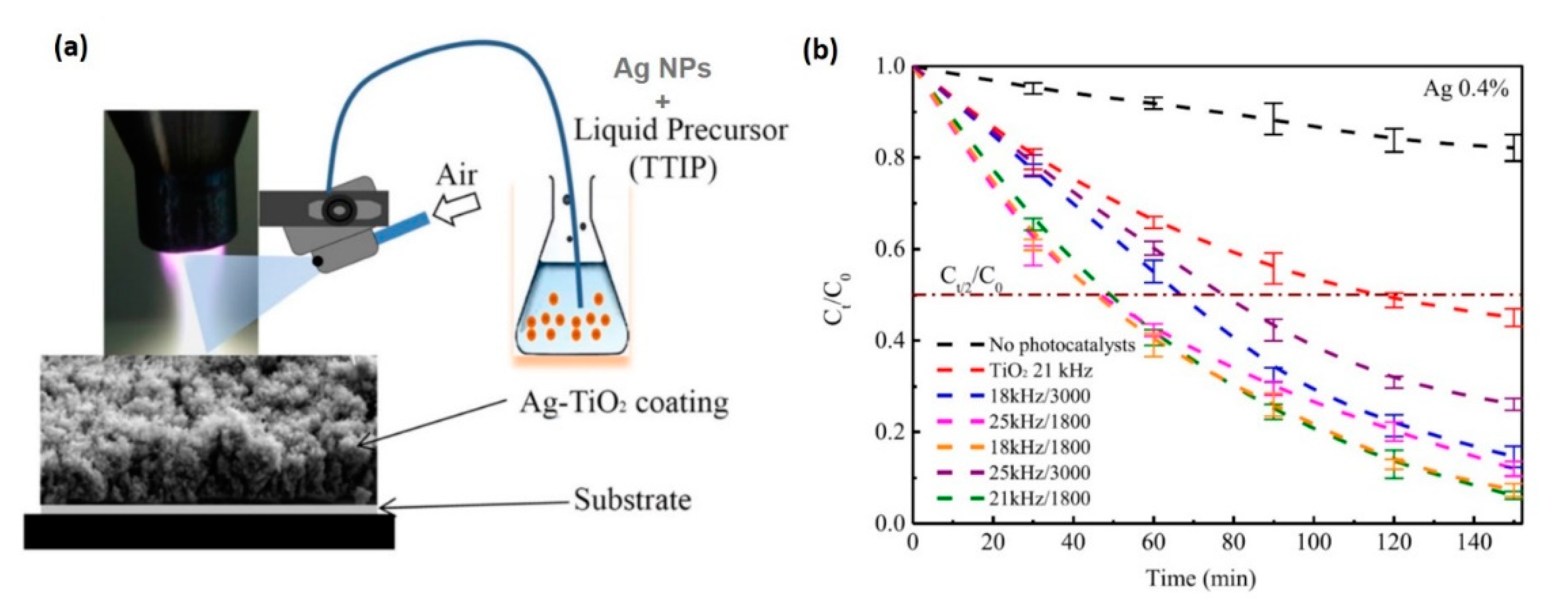
5.3. Atmospheric Pressure Dielectric Barrier Discharge Deposition

Finally, the last method for TiO2 plasma deposition described in this review is APP ignited based on DBD, including atmospheric filamentary discharge [107], diffuse coplanar discharge [108], and APPJ, for which the term “torch” is used sometimes rather than “jet”. Moreover, a combination of two methods, e.g., APPJ with CVD [90,91,109], can be used to synthesize and/or treat materials.
In 2018, atmospheric filamentary DBD was used for the first time to synthesize TiO2 films with a different morphology that can be achieved in a controlled manner [107]. In this work, the effect of various plasma parameters, i.e., gas flow rate, concentration of TTIP precursor, total gas flow, plasma power, and deposition time, was investigated systematically. By tuning these parameters, the density of the deposited films varied from loosely dense powders to a dense and compact anatase crystalline phase with enhanced photocatalytic activity [107]. Moreover, the authors proposed a deposition mechanism that explained the effect of plasma parameters on the film morphology. This mechanism consisted of three stages, including the formation of excited and reactive species in the discharge, chemical reactions that initiate the nucleation process, and growth saturation processes. According to this mechanism, the morphology of the deposited film depends strongly on the energy density in these stages. This study was extended subsequently to N-doped TiO2 films using the same experimental set-up for APP with varying concentrations of NH3 in Ar plasma, which led to the formation of NH radicals [43]. A comparison of N-doped films revealed a lower band gap and a higher (approximately 1.4 times) photocatalytic degradation rate constant than those for the undoped TiO2 films.
Similarly, as in PECVD, the APDBDD methodology was also employed in TiO2 nanoparticle synthesis with controllable size, distribution, and morphology by tuning such plasma parameters as plasma power, frequency, and the molar ratio of precursors and feed gas [110]. The results from this method were compared with those from the furnace reactor and commercial aerosol generators and showed its great potential as an aerosol generator to produce solid spherical particles.
In addition to using APDBDD to synthesize nanoparticles, this method has also been used to deposit pre-synthesized TiO2 nanoparticles in the form of a nanocomposite thin film onto a Si substrate [111]. This study reported that the advantage of this method was its ability to deposit the nanoparticles directly onto a substrate. Moreover, the discharge parameters, particularly the voltage waveform and frequency, controlled the nanoparticle coverage and thickness. This process is particularly beneficial for industrial scale-up, where film thickness needs to be homogeneous over a large surface area of the substrate.
Further, APPJ can be used to obtain highly porous films or nanoparticles, which are important for certain applications, particularly when a high surface-to-volume ratio is desired. Although PECVD provides a high deposition rate for thin uniform films, compared to that using APPJ, porosity is very difficult to achieve with the PECVD process.
In Fakhouri et al.’s recent work [16], a precisely controlled and porous TiO2 film grown on membranes using APPJ was compared with a nonporous thin film deposited by rf magnetron sputtering with respect to PEC and photocatalytic activities. On the one hand, a thin film grown by APPJ showed better photocatalytic activity, inducing rhodamine B (Rh.B) dye (i.e., a fluorescent material) degradation more effectively in the presence of TiO2 with elevated porosity under white light irradiation than in the sputtered deposited film. On the other hand, the PEC responses were superior for rf magnetron-sputtered deposited film [16]. Similarly, Rh.B was used to investigate the photocatalytic activity of nano-Ag–TiO2 coatings deposited by APPJ (Figure 9) [112]. By combining the APPJ with a spraying system, high deposition rates were achieved in the range of 10–20 μm/s. Using this method, large photocatalytic activities were measured for coating from solutions with 0.3% and 0.4% Ag concentrations in TTIP. In this study, the authors concluded that pulse frequencies had a negligible effect on Rh.B degradation, whereas lower air flow rates induced a faster kinetics because such conditions caused higher crystallinity of the coating [112].
In general, the high porosity of APPJ-grown films was attributed to the high deposition rate and high kinetic energy of the reactive plasma species (i.e., radicals) generated and carried in the plasma jet. In this process, the plasma species on the surface have a limited time to diffuse, which promotes higher porosity [16]. The high kinetic energy of plasma species, which is another contributing factor to the high porosity, was also responsible for the lower surface mobility of these species. In addition to investigating the deposition rate, the crystalline phases of APPJ-deposited TiO2 films were explored [16]. This research showed that the anatase crystalline phase was dominant in the case of films with a highly porous morphology. Moreover, regardless of the deposition parameters, the crystal size increased with increasing substrate temperature as well as increasing pulse frequency, which consequently increased the temperature. It is worth noting that carbonaceous contamination of the film quenched with increasing frequency.
Several other investigations that used atmospheric DBD focused on finding optimal conditions for TiO2 film deposition that exhibited high photocatalytic activity. For example, Boscher et al. used an atmospheric pressure N2 blown arc discharge with an injection of TIPO as a precursor to deposit anatase TiO2 thin films, which were then tested for their photocatalytic activity [94]. In this study, key factors, such as power density, the nozzle-to-substrate distance, and the injector-to-substrate distance, were varied to identify the optimal operating conditions. The results showed that reducing both distances led to a shorter residence time and a more reactive zone between the injector and the substrate. These conditions contributed to the formation of anatase crystalline clusters, which improved the photocatalytic activity of films [94].
In another study in which TiO2 was also used for energy conversion-related applications, a mesoporous TiO2 film was fabricated on a small area via an APPJ method using TiCl4/O2 precursor [64]. The results showed that the deposition rate was 25 times higher when this method was used than the ratios reported using PECVD. Some chlorine-based and carbonaceous contamination was present in the “as-deposited” film, but this could be removed by post-deposition annealing. Nevertheless, the films deposited with this method exhibited an almost 50% higher photoconversion efficiency, attributed to high porosity compared to commercial TiO2 nanoparticles, when both were employed as photoanodes in DSSCs [64]. Further, fluorine-doped tin oxide (FTO)-coated glass was used as the substrate in this study, because this material favored the formation of anatase TiO2 at 200 °C. Similarly, TiO2 thin films deposited on a FTO substrate were treated by Ar/N2 APPJ to dope the surface with nitrogen atoms [70]. The anatase crystalline phase increased because of plasma treatment, which was then used for DSSC assembly. Overall, this treatment reduced any impurities and incorporated nitrogen atoms on the surface, which enhanced DSSC’s performance by approximately 1.5%. The studies above have shown that post-deposition treatment of thin films by APPJs was beneficial in these cases, particularly those in which chemical composition and intrinsic thin film properties were changed in a controlled manner. Another advantage of APPJ (as well as diffuse coplanar DBD [108]) is to use plasma for sintering in DSSC applications [22,113,114]. Several studies that have used various analyses of TiO2 films and nanoparticles demonstrated plasma’s ability to reduce time and temperature in material sintering significantly in comparison to thermal sintering.
In another study, Chou et al. also showed the benefits of APPJ treatment used to calcinate a TiO2 photoanode incorporated into a DSSC [115]. The authors were able to obtain a significantly shorter time for calcination of electrodes for the DSSC, which exhibited cell performance comparable to that obtained from a cell for which a furnace was used for electrode calcination. APPJ’s ultrafast deposition and calcination of photoanodes enables the rapid preparation of DSSCs, which makes this technology suitable for industrial roll-to-roll fabrication [115]. A recent review summarized a large number of studies and indicated future directions for the technology, in which APPJ can be used to process porous materials, including TiO2, to advance its applications in energy harvesting and storage devices [116].
In addition to using APPJ to form porous films, this methodology was also used to produce TiO2 powders from a TiCl4 precursor and air [117]. In this study, the morphology varied when the distance between the plasma nozzle and the substrate was changed, demonstrating the appearance of the anatase crystalline size for powders deposited at short distances when the gas temperature was the highest, while, at greater distances, the size of powder granules and Cl contamination increased [117].
The use of APPJ based on DBD to coat and treat materials has been a rapidly growing methodology over the past two decades. Because of its undeniable industrial advantages, such as the reduced cost of instrumentation, lower operating temperatures, easier handling and maintenance, convenient operation, and possibility of combining it with other methods, it is an appealing tool as an alternative deposition technique. Its drawbacks are the greater number of plasma parameters that need to be tuned to obtain the desired effect, as well as the possibility of material/surface contamination and more complex physical and chemical processes in plasma, as APPJs are often operated in open air. A recent review paper provided a critical view of APPJ technology in surface processing of materials, including TiO2 [66].
The most important plasma and deposition parameters and post-treatment conditions and their effects on film morphology, as well as the scope and applications of selected studies using different types of atmospheric pressure DBD-based discharge deposition technique, are summarized in Table 3.

6. Summary and Outlook

This review reported three common APP-enhanced methods to deposit TiO2 thin films: plasma-enhanced chemical deposition, atomic layer deposition, and atmospheric pressure–dielectric barrier discharge deposition. In most of the works reported in the literature, the TiO2 thin film was deposited using the plasma-enhanced chemical deposition method because of its simplicity, low cost, rapid deposition, and low-temperature regime. Other methods were also used, but they were explored for specific applications, such as photocatalytic and photo-electrochemical processes.
This review also summarized recent findings on the effects of various deposition parameters on the structural, electronic, and optical properties of TiO2 films using these three methods. An excellent benefit of these methods is that, by tuning the deposition parameters, one can engineer TiO2 films that can then be exploited for a range of applications, particularly energy conversion devices.
One of the focuses here was on comparing the deposition rates using these different methods. As is now well established, PECVD and APPJ can be used for much faster deposition than conventional deposition methods, while PEALD can be used for slow and more controlled layer-by-layer deposition. However, researchers have recently shown that PEALD can also be useful for commercial production.
Further, the formation of the final phase of TiO2 thin films or nanostructures, as well as the transition between phases, was another particular focus in this review. For example, amorphous smooth films can be obtained at room temperature using PECVD, while the anatase phase was found only when a substrate was at an elevated temperature during growth or post-deposition annealing (between 200–300 °C). Further, the rutile phase is obtained at an even higher temperature. However, the latest studies have also shown the formation of TiO2 anatase films using room-temperature PEALD.
Nevertheless, conventional deposition techniques need a higher temperature to achieve crystallinity than the plasma-enhanced methods. This is because reactive species produced in the plasma discharge can help produce crystalline film. This is a significant advantage in certain specific applications in which high temperatures could lead to undesired material alteration.
Moreover, because the crystal phase influences film properties—for example, the anatase phase exhibits a lower dielectric coefficient—the anatase/rutile mixture ratio can be controlled by changing the plasma reactive species energy. In the case when ions and electrons possess excessively high energy, they can hinder film growth and crystallization by preventing the densification and creating defects and vacancies. In contrast, post-deposition plasma treatment can produce better crystallinity by removing the oxygen vacancies, which increases the photocatalytic efficiency of TiO2 films.
In addition to deposition rate and crystal phase transition, the possibility of impurity incorporation was also addressed in this review when the results obtained with a particular deposition method were described.
Although TiO2 deposition by APPs has been studied and examined in detail, there are numerous unexplored areas that remain to be addressed. More research on consistency is needed with respect to the replicability of crystal phases, which requires a complete understanding of fundamental processes, including plasma reactive species interactions with the surface. Understanding such surface reactions will provide further opportunities to control the structural, electric, and optical properties, which several factors can influence. Among these, deposition parameters, e.g., flow rate of plasma gases and precursors, choice of precursors, plasma power, substrate temperature, deposition duration, and so on, as well as their synergistic interactions, are crucial in altering films. In addition to empirical effort toward improving the description of the effects of the plasma parameters on the attributes of deposited films and their evolution, theoretical and computational efforts are required to deepen our understanding and fill in the knowledge gaps that are challenging and more time-consuming, and thus, more expensive to investigate experimentally. Therefore, predictive modeling of various features of deposited films for any plasma parameter can provide immense opportunities to shed light on this challenge. Nowadays, predictive modeling with machine learning is emerging as a ubiquitous technology, and its scope and application to material science and specifically to material design is receiving significant research attention. There are reported works on using machine learning algorithms to model plasma surface interactions occurring in a given target [118,119,120]. Employing machine-learning-based models not only helps to predict a given outcome, but it also opens possibilities to find the optimal and desired parameter combinations that would be ideal for the deposition process. The scope of implementing and blending predictive modeling, specifically with modern machine learning algorithms, provides great prospects and should be considered to explore the APP field further. Moreover, in order to apply machine learning algorithms, a large, high-quality and reproducible data set from experimental studies is needed. However, impurities and defects can be either beneficial or disadvantageous, depending on the applications of the synthesized materials. Hence, more insight is required into plasma deposition techniques that can be used to control impurities and defects. Although the plasma-enhanced deposition rate is typically higher than that of other conventional techniques, it is still far from industrial scale-up and replicability of the electronic grade of TiO2 thin films. Synthesizing different nanostructures, deposition of pre-synthesized nanoparticles of TiO2 by plasma, and plasma treatment also face similar challenges.
Research on APP deposition has immense potential to be one of the most popular research topics in the coming decades. Overall, APP deposition can compete with the conventional deposition techniques used in scientific laboratories as well as in industrial research.

Author Contributions

Collecting materials, writing, and editing, S.B., E.A., P.S., A.S. and S.P. All authors have read and agreed to the published version of the manuscript.

Funding

This material is based upon work supported by the U.S. Department of Energy Office of Science, Office of Basic Energy Sciences under Award Number DE-FC02-04ER15533. This is contribution number NDRL 5288 from the Notre Dame Radiation Laboratory.

Conflicts of Interest

The authors declare no conflict of interest.

References

  1. Dowling, D.P.; Stallard, C.P. Achieving enhanced material finishing using cold plasma treatments. Trans. IMF 2015, 93, 119–125. [Google Scholar] [CrossRef]
  2. Tendero, C.; Tixier, C.; Tristant, P.; Desmaison, J.; Leprince, P. Atmospheric pressure plasmas: A review. Spectrochim. Acta Part B Spectrosc. 2006, 61, 2–30. [Google Scholar] [CrossRef]
  3. Chen, F.F. Introduction to Plasma Physics and Controlled Fusion, 2nd ed.; Plenum Press: New York, NY, USA, 1984. [Google Scholar]
  4. Park, S.; Choe, W.; Moon, S.Y.; Yoo, S.J. Electron characterization in weakly ionized collisional plasmas: From principles to techniques. Adv. Phys. X 2019, 4, 1526114. [Google Scholar] [CrossRef] [Green Version]
  5. Penkov, O.V.; Khadem, M.; Lim, W.S.; Kim, D.E. A review of recent applications of atmospheric pressure plasma jets for materials processing. J. Coat. Technol. Res. 2015, 12, 225–235. [Google Scholar] [CrossRef]
  6. Kakiuchi, H.; Ohmi, H.; Yasutake, K. Atmospheric-pressure low-temperature plasma processes for thin film deposition. J. Vac. Sci. Technol. A Vac. Surf. Film. 2014, 32, 030801-1–030801-16. [Google Scholar] [CrossRef]
  7. Schutze, A.; Jeong, J.J.Y.; Babayan, S.E.; Park, J.; Selwyn, G.S.; Hicks, R.F. The Atmospheric-Pressure Plasma Jet: A Review and Comparison to Other Plasma Sources. IEEE Trans. Plasma Sci. 1998, 26, 1685–1694. [Google Scholar] [CrossRef] [Green Version]
  8. Pappas, D. Status and potential of atmospheric plasma processing of materials. J. Vac. Sci. Technol. A Vac. Surf. Film. 2011, 29, 020801-1–020801-17. [Google Scholar] [CrossRef] [Green Version]
  9. Thornton, J.A. Plasma-assisted deposition processes: Theory, mechanisms and applications. Thin Solid Film. 1983, 107, 3–19. [Google Scholar] [CrossRef]
  10. Taylor, P.R.; Pirzada, S.A. Thermal plasma processing of materials: A review. Adv. Perform. Mater. 1994, 1, 35–50. [Google Scholar] [CrossRef]
  11. Peng, X.; Matthews, A.; Xue, S. Plasma-based processes and thin film equipment for nano-scale device fabrication. J. Mater. Sci. 2011, 46, 1–37. [Google Scholar] [CrossRef]
  12. Vallée, C.; Bonvalot, M.; Belahcen, S.; Yeghoyan, T.; Jaffal, M.; Vallat, R.; Chaker, A.; Lefèvre, G.; David, S.; Bsiesy, A.; et al. Plasma deposition—Impact of ions in plasma enhanced chemical vapor deposition, plasma enhanced atomic layer deposition, and applications to area selective deposition. J. Vac. Sci. Technol. A 2020, 38, 033007. [Google Scholar] [CrossRef]
  13. Fanelli, F.; Bosso, P.; Mastrangelo, A.M.; Fracassi, F. Thin film deposition at atmospheric pressure using dielectric barrier discharges: Advances on three-dimensional porous substrates and functional coatings. Jpn. J. Appl. Phys. 2016, 55, 07LA01. [Google Scholar] [CrossRef]
  14. Fauchais, P.; Vardelle, M.; Vardelle, A.; Bianchi, L. Plasma spray: Study of the coating generation. Ceram. Int. 1996, 22, 295–303. [Google Scholar] [CrossRef]
  15. Takahashi, Y.; Shibata, Y.; Maeda, M.; Miyano, Y.; Murai, K.; Ohmori, A. Plasma-spraying synthesis of high-performance photocatalytic TiO2 coatings. IOP Conf. Ser. Mater. Sci. Eng. 2014, 61, 012039-1–012039-10. [Google Scholar] [CrossRef]
  16. Fakhouri, H.; Salem, D.B.; Carton, O.; Pulpytel, J.; Arefi-Khonsari, F. Highly efficient photocatalytic TiO2 coatings deposited by open air atmospheric pressure plasma jet with aerosolized TTIP precursor. J. Phys. D Appl. Phys. 2014, 47, 265301-1–265301-11. [Google Scholar] [CrossRef]
  17. Chen, D.; Jordan, E.H.; Gell, M. Porous TiO2 coating using the solution precursor plasma spray process. Surf. Coat. Technol. 2008, 202, 6113–6119. [Google Scholar] [CrossRef]
  18. Chen, D.; Jordan, E.H.; Gell, M.; Ma, X. Dense TiO2 Coating Using the Solution Precursor Plasma Spray Process. J. Am. Ceram. Soc. 2008, 91, 865–872. [Google Scholar] [CrossRef]
  19. Bessergenev, V.G.; Khmelinskii, I.V.; Pereira, R.J.F.; Krisuk, V.V.; Turgambaeva, A.E.; Igumenov, I.K. Preparation of TiO2 films by CVD method and its electrical, structural and optical properties. Vacuum 2002, 64, 275–279. [Google Scholar] [CrossRef]
  20. O’Neill, S.A.; Parkin, I.P.; Clark, R.J.H.; Mills, A.; Elliott, N. Atmospheric pressure chemical vapour deposition of titanium dioxide coatings on glass. J. Mater. Chem. 2003, 13, 56–60. [Google Scholar] [CrossRef]
  21. Kanazawa, T.; Ohmori, A. Behavior of TiO2 coating formation on PET plate by plasma spraying and evaluation of coating’s photocatalytic activity. Surf. Coat. Technol. 2005, 197, 45–50. [Google Scholar] [CrossRef]
  22. Jung, H.; Park, J.; Yoo, E.S.; Han, G.-S.; Jung, H.S.; Ko, M.J.; Park, S.; Choe, W. Functionalization of nanomaterials by non-thermal large area atmospheric pressure plasmas: Application to flexible dye-sensitized solar cells. Nanoscale 2013, 5, 7825–7830. [Google Scholar] [CrossRef] [PubMed]
  23. Guo, X.; Ma, T.P. Tunneling leakage current in oxynitride: Dependence on oxygen/nitrogen content. IEEE Electron Device Lett. 1998, 19, 207–209. [Google Scholar] [CrossRef]
  24. Fujishima, A.; Rao, T.N.; Tryk, D.A. Titanium dioxide photocatalysis. J. Photochem. Photobiol. C Photochem. Rev. 2000, 1, 1–21. [Google Scholar] [CrossRef]
  25. Malagutti, A.R.; Mourão, H.A.J.L.; Garbin, J.R.; Ribeiro, C. Deposition of TiO2 and Ag:TiO2 thin films by the polymeric precursor method and their application in the photodegradation of textile dyes. Appl. Catal. B Environ. 2009, 90, 205–212. [Google Scholar] [CrossRef]
  26. Luttrell, T.; Halpegamage, S.; Tao, J.; Kramer, A.; Sutter, E.; Batzill, M. Why is anatase a better photocatalyst than rutile?—Model studies on epitaxial TiO2 films. Sci. Rep. 2015, 4, 1–8. [Google Scholar] [CrossRef] [Green Version]
  27. Davidsdóttir, S.; Canulescu, S.; Dirscherl, K.; Schou, J.; Ambat, R. Investigation of photocatalytic activity of titanium dioxide deposited on metallic substrates by DC magnetron sputtering. Surf. Coat. Technol. 2013, 216, 35–45. [Google Scholar] [CrossRef]
  28. Carp, O.; Huisman, C.L.; Reller, A. Photoinduced reactivity of titanium dioxide. Prog. Solid State Chem. 2004, 32, 33–177. [Google Scholar] [CrossRef]
  29. Augugliaro, V.; Loddo, V.; Pagliaro, M.; Palmisano, G.; Palmisano, L. Clean by Light Irradiation: Practical Applications of Supported TiO2; The Royal Society of Chemistry: London, UK, 2011. [Google Scholar]
  30. Fujishima, A.; Zhang, X.; Tryk, D.A. TiO2 photocatalysis and related surface phenomena. Surf. Sci. Rep. 2008, 63, 515–582. [Google Scholar] [CrossRef]
  31. Fujishima, A.; Hashimoto, K.; Watanabe, T. TiO2 Photocatalysis: Fundamentals and Applications; Tokyo Bkc Inc.: Tokyo, Japan, 1999. [Google Scholar]
  32. Xu, J.; Nagasawa, H.; Kanezashi, M.; Tsuru, T. UV-Protective TiO2 Thin Films with High Transparency in Visible Light Region Fabricated via Atmospheric-Pressure Plasma-Enhanced Chemical Vapor Deposition. ACS Appl. Mater. Interfaces 2018, 10, 42657–42665. [Google Scholar] [CrossRef]
  33. Evans, P.; Sheel, D.W. Photoactive and antibacterial TiO2 thin films on stainless steel. Surf. Coat. Technol. 2007, 201, 9319–9324. [Google Scholar] [CrossRef]
  34. Karches, M.; Morstein, M.; von Rohr, R.P.; Pozzo, R.L.; Giombi, J.L.; Baltanás, M.A. Plasma-CVD-coated glass beads as photocatalyst for water decontamination. Catal. Today 2002, 72, 267–279. [Google Scholar] [CrossRef]
  35. Fagan, R.; McCormack, D.E.; Dionysiou, D.D.; Pillai, S.C. A review of solar and visible light active TiO2 photocatalysis for treating bacteria, cyanotoxins and contaminants of emerging concern. Mater. Sci. Semicond. Process. 2016, 42, 2–14. [Google Scholar] [CrossRef] [Green Version]
  36. Thukkaram, M.; Cools, P.; Nikiforov, A.; Rigole, P.; Coenye, T.; Van Der Voort, P.; Du Laing, G.; Vercruysse, C.; Declercq, H.; Morent, R.; et al. Antibacterial activity of a porous silver doped TiO2 coating on titanium substrates synthesized by plasma electrolytic oxidation. Appl. Surf. Sci. 2020, 500, 144235. [Google Scholar] [CrossRef]
  37. Lee, D.G.; Lee, D.; Yoo, J.S.; Lee, S.; Jung, H.S. Effective passivation of Ag nanowire-based flexible transparent conducting electrode by TiO2 nanoshell. Nano Converg. 2016, 3. [Google Scholar] [CrossRef] [PubMed] [Green Version]
  38. Schneider, J.; Matsuoka, M.; Takeuchi, M.; Zhang, J.; Horiuchi, Y.; Anpo, M.; Bahnemann, D.W. Understanding TiO2 Photocatalysis: Mechanisms and Materials. Chem. Rev. 2014, 114, 9919–9986. [Google Scholar] [CrossRef] [PubMed]
  39. Asahi, R.; Morikawa, T.; Ohwaki, T.; Aoki, K.; Taga, Y. Visible-Light Photocatalysis in Nitrogen-Doped Titanium Oxides. Science 2001, 293, 269–271. [Google Scholar] [CrossRef]
  40. Hovish, M.Q.; Dauskardt, R.H. Optical properties of metal oxynitride thin films grown with atmospheric plasma deposition. J. Phys. D Appl. Phys. 2016, 49. [Google Scholar] [CrossRef]
  41. Kot, M.; Łobaza, J.; Naumann, F.; Gargouri, H.; Henkel, K.; Schmeißer, D. Long-term ambient surface oxidation of titanium oxynitride films prepared by plasma-enhanced atomic layer deposition: An XPS study. J. Vac. Sci. Technol. A 2018, 36, 01A114. [Google Scholar] [CrossRef]
  42. Hovish, M.Q.; Hilt, F.; Rolston, N.; Xiao, Q.; Dauskardt, R.H. Open Air Plasma Deposition of Superhydrophilic Titania Coatings. Adv. Fun. Mat. 2019, 29, 1806421. [Google Scholar] [CrossRef]
  43. Chen, Q.; Ozkan, A.; Chattopadhyay, B.; Baert, K.; Poleunis, C.; Tromont, A.; Snyders, R.; Delcorte, A.; Terryn, H.; Delplancke-Ogletree, M.-P.; et al. N-Doped TiO2 Photocatalyst Coatings Synthesized by a Cold Atmospheric Plasma. Langmuir 2019, 35, 7161–7168. [Google Scholar] [CrossRef] [Green Version]
  44. Haidera, A.J.; Jameel, Z.N.; Al-Hussainib, I.H.M. Review on: Titanium Dioxide Applications. Energy Procedia 2019, 157, 17–29. [Google Scholar] [CrossRef]
  45. Kumaravel, V.; Mathew, S.; Bartlett, J.; Pillaiab, S.C. Photocatalytic hydrogen production using metal doped TiO2: A review of recent advances. App. Catal. B 2019, 244, 1021–1064. [Google Scholar] [CrossRef]
  46. Rajaraman, T.S.; Parikh, S.P.; Gandhi, V.G. Black TiO2: A review of its properties and conflicting trends. Chem. Eng. J. 2020, 389, 123918. [Google Scholar] [CrossRef]
  47. Noman, M.T.; Ashraf, M.A.; Ali, A. Synthesis and applications of nano-TiO2: A review. Environ. Sci. Pollut. Res. 2019, 26, 3262–3291. [Google Scholar] [CrossRef] [PubMed]
  48. Martinu, L.; Poitras, D. Plasma deposition of optical films and coatings: A review. J. Vac. Sci. Technol. A Vac. Surf. Film. 2000, 18, 2619–2645. [Google Scholar] [CrossRef]
  49. Yoshiki, H.; Saito, T. Preparation of TiO2 thin films on the inner surface of a quartz tube using atmospheric-pressure microplasma. J. Vac. Sci. Technol. A Vac. Surf. Film. 2008, 26, 338–343. [Google Scholar] [CrossRef]
  50. Filippin, A.N.; Sanchez-Valencia, J.R.; Idígoras, J.; Rojas, T.C.; Barranco, A.; Anta, J.A.; Borras, A. Plasma enhanced deposition of single and multistacked TiO2 hierarchical nanotube photoanodes. Nanoscale 2017, 9, 8133–8141. [Google Scholar] [CrossRef]
  51. Gazal, Y.; Dublanche-Tixier, C.; Chazelas, C.; Colas, M.; Carles, P.; Tristant, P. Multi-structural TiO2 film synthesised by an atmospheric pressure plasma-enhanced chemical vapour deposition microwave torch. Thin Solid Film. 2016, 600, 43–52. [Google Scholar] [CrossRef]
  52. Yamauchi, S.; Imai, Y. Plasma-Assisted Chemical Vapor Deposition of TiO2 Thin Films for Highly Hydrophilic Performance. Cryst. Struct. Theory Appl. 2013, 2, 1–7. [Google Scholar] [CrossRef] [Green Version]
  53. Wang, S.; Wang, K.; Jehng, J.; Liu, L. Preparation of TiO2/MCM-41 by plasma enhanced chemical vapor deposition method and its photocatalytic activity. Front. Environ. Sci. Eng. 2012, 6, 304–312. [Google Scholar] [CrossRef]
  54. Yang, W.; Wolden, C.A. Plasma-enhanced chemical vapor deposition of TiO2 thin films for dielectric applications. Thin Solid Film. 2006, 515, 1708–1713. [Google Scholar] [CrossRef]
  55. Dalapati, G.K.; Chatterjee, S.; Samanta, S.K.; Maiti, C.K. Electrical characterization of low temperature deposited TiO2 films on strained-SiGe layers. Appl. Surf. Sci. 2003, 210, 249–254. [Google Scholar] [CrossRef]
  56. Lee, G.W.; Woo, S.I.; Kim, J.C.; Oh, K.H. Preparation and properties of amorphous TiO2 thin films by plasma enhanced chemical vapor deposition. Thin Solid Film. 1994, 237, 105–111. [Google Scholar] [CrossRef]
  57. Frenck, H.J.; Kulisch, W.; Kuhr, M.; Kassing, R. Deposition of TiO2 thin films by plasma-enhanced decompostion of tetraisopropyltitanate. Thin Solid Film. 1991, 201, 327–335. [Google Scholar] [CrossRef]
  58. Borras, A.; Sanchez-Valencia, J.R.; Widmer, R.; Rico, V.J.; Justo, A.; Gonzalez-Elipe, A.R. Growth of Crystalline TiO2 by Plasma Enhanced Chemical Vapor Deposition. Cryst. Growth Des. 2009, 9, 2868–2876. [Google Scholar] [CrossRef]
  59. Lee, Y.H. A role of energetic ions in RF-biased PECVD of TiO2. Vacuum 1998, 51, 503. [Google Scholar] [CrossRef]
  60. Maiti, C.K.; Samanta, S.K.; Dalapati, G.K.; Nandi, S.K.; Chatterjee, S. Electrical characterization of TiO2 gate oxides on strained-Si. Microelectron. Eng. 2004, 72, 253–256. [Google Scholar] [CrossRef]
  61. Hao, Q.; Fu, X.; Song, S.; Gibson, D.; Li, C.; Chu, H.O.; Shi, Y. Investigation of TiO2 Thin Film Deposited by Microwave Plasma Assisted Sputtering and Its Application in 3D Glasses. Coatings 2018, 8, 270. [Google Scholar] [CrossRef] [Green Version]
  62. Medvecká, V.; Kováčik, D.; Zahoranová, A.; Černák, M. Atmospheric pressure plasma enhanced calcination by the preparation of TiO2 fibers in submicron scale. Appl. Surf. Sci. 2018, 428, 609–615. [Google Scholar] [CrossRef]
  63. Mertens, J.; Hubert, J.; Vandencasteele, N.; Raes, M.; Terryn, H.; Reniers, F. Chemical and physical effect of SiO2 and TiO2 nanoparticles on highly hydrophobic fluorocarbon hybrid coatings synthesized by atmospheric plasma. Surf. Coat. Technol. 2017, 315, 274–282. [Google Scholar] [CrossRef]
  64. Seo, H.K.; Elliott, C.M.; Shin, H.S. Mesoporous TiO2 films fabricated using atmospheric pressure dielectric barrier discharge jet. ACS Appl. Mater. Interfaces 2010, 2, 3397–3400. [Google Scholar] [CrossRef]
  65. Di, L.B.; Li, X.S.; Shi, C.; Xu, Y.; Zhao, D.Z.; Zhu, A.M. Atmospheric-pressure plasma CVD of TiO2 photocatalytic films using surface dielectric barrier discharge. J. Phys. D Appl. Phys. 2009, 42, 032001–032004. [Google Scholar] [CrossRef]
  66. Fanelli, F.; Fracassi, F. Atmospheric pressure non-equilibrium plasma jet technology: General features, specificities and applications in surface processing of materials. Surf. Coat. Technol. 2017, 322, 174–201. [Google Scholar] [CrossRef]
  67. Park, J.J.; Lee, W.J.; Lee, G.H.; Kim, I.S.; Shin, B.C.; Yoon, S.G. Very thin TiO2 films Prepared by Plasma Enhanced Atomic Layer Deposition (PEALD). Integr. Ferroelectr. 2004, 68, 129–137. [Google Scholar] [CrossRef]
  68. Choi, G.; Kim, S.K.; Won, S.; Kim, H.J.; Hwang, C.S. Plasma-Enhanced Atomic Layer Deposition of TiO2 and Al-Doped TiO2 Films Using N2O and O2 Reactants. J. Electrochem. Soc. 2009, 156, G138–G143. [Google Scholar] [CrossRef]
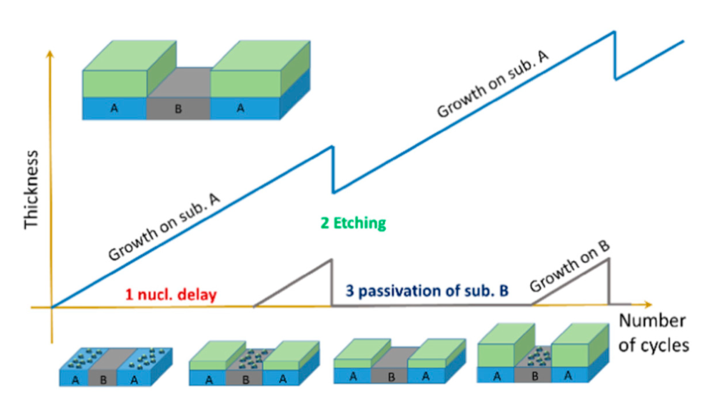
  69. Vallat, R.; Gassilloud, R.; Salicio, O.; El Hajjam, K.; Molas, G.; Pelissier, B.; Vallée, C. Area selective deposition of TiO2 by intercalation of plasma etching cycles in PEALD process: A bottom up approach for the simplification of 3D integration scheme. J. Vac. Sci. Technol. A 2019, 37, 020918. [Google Scholar] [CrossRef]
  70. Yuji, T.; Akatsuka, H.; Mungkung, N.; Park, B.W.; Sung, Y.M. Surface treatment of TiO2 films for dye-sensitized solar cells using atmospheric-pressure non-equilibrium DC pulse discharge plasma jet. Vacuum 2009, 83, 124–127. [Google Scholar] [CrossRef]
  71. Ha, H.; Yoshimoto, M.; Koinuma, H.; Moon, B.; Ishiwara, H. Open air plasma chemical vapor deposition of highly dielectric amorphous TiO2 films. Appl. Phys. Lett. 1996, 68, 2965–2967. [Google Scholar] [CrossRef]
  72. Jiménez, C.; De Barros, D.; Darraz, A.; Deschanvres, J.-L.; Rapenne, L.; Chaudouët, P.; Méndez, J.E.; Weiss, F.; Thomachot, M.; Sindzingre, T.; et al. Deposition of TiO2 thin films by atmospheric plasma post-discharge assisted injection MOCVD. Surf. Coat. Technol. 2007, 201, 8971–8975. [Google Scholar] [CrossRef] [Green Version]
  73. Williams, L.M.; Hess, D.W. Structural properties of titanium dioxide films deposited in an rf glow discharge. J. Vac. Sci. Technol. A 1983, 1, 1810–1819. [Google Scholar] [CrossRef]
  74. Williams, L.M.; Hess, D.W. Photoelectrochemical properties of plasma-deposited TiO2 thin films. Thin Solid Film. 1984, 115, 13–18. [Google Scholar] [CrossRef]
  75. Collette, S.; Hubert, J.; Batan, A.; Baert, K.; Raes, M.; Vandendael, I.; Daniel, A.; Archambeau, C.; Terryn, H.; Reniers, F. Photocatalytic TiO2 thin films synthesized by the post-discharge of an RF atmospheric plasma torch. Surf. Coat. Technol. 2016, 289, 172–178. [Google Scholar] [CrossRef]
  76. Xu, Y.; Zhang, Y.; He, T.; Ding, K.; Huang, X.; Li, H.; Shi, J.; Guo, Y.; Zhang, J. The Effects of Thermal and Atmospheric Pressure Radio Frequency Plasma Annealing in the Crystallization of TiO2 Thin Films. Coatings 2019, 9, 357. [Google Scholar] [CrossRef] [Green Version]
  77. Xu, Y.; Zhang, Y.; Li, L.; Ding, K.; Guo, Y.; Shi, J.; Huang, X.; Zhang, J. Synergistic Effect of Plasma Discharge and Substrate Temperature in Improving the Crystallization of TiO2 Film by Atmospheric Pressure Plasma Enhanced Chemical Vapor Deposition. Plasma Chem. Plasma Process. 2019, 39, 937–947. [Google Scholar] [CrossRef]
  78. Mauchauffé, R.; Kang, S.; Kim, J.; Kim, J.H.; Moon, S.Y. Spectroscopic study of an atmospheric pressure plasma generated for the deposition of titanium dioxide thin films. Curr. Appl. Phys. 2019, 19, 1296–1304. [Google Scholar] [CrossRef]
  79. Huang, S.S.; Chen, J.S. Comparison of the characteristics of TiO2 films prepared by low-pressure and plasma-enhanced chemical vapor deposition. J. Mater. Sci. Mater. Electron. 2002, 13, 77–81. [Google Scholar] [CrossRef]
  80. Nakamura, M.; Kato, S.; Aoki, T.; Sirghi, L.; Hatanaka, Y. Formation mechanism for TiOx thin film obtained by remote plasma enhanced chemical vapor deposition in H2–O2 mixture gas plasma. Thin Solid Film. 2001, 401, 138–144. [Google Scholar] [CrossRef]
  81. Mathur, S.; Kuhn, P. CVD of titanium oxide coatings: Comparative evaluation of thermal and plasma enhanced processes. Surf. Coat. Technol. 2006, 201, 807–814. [Google Scholar] [CrossRef]
  82. Rie, K.T.; Gebauer, A.; Wohle, J. Plasma assisted CVD for low temperature coatings to improve the wear and corrosion resistance. Surf. Coat. Technol. 1996, 86–87, 498–506. [Google Scholar] [CrossRef]
  83. Kang, S.; Mauchauffé, R.; You, Y.S.; Moon, S.Y. Insights into the Role of Plasma in Atmospheric Pressure Chemical Vapor Deposition of Titanium Dioxide Thin Films. Sci. Rep. 2018, 8, 16684-1–16684-13. [Google Scholar] [CrossRef] [Green Version]
  84. Baba, K.; Bulou, S.; Choquet, P.; Boscher, N.D. Photocatalytic Anatase TiO2 Thin Films on Polymer Optical Fiber Using Atmospheric-Pressure Plasma. ACS Appl. Mater. Interfaces 2017, 9, 13733–13741. [Google Scholar] [CrossRef] [PubMed]
  85. Ahn, K.H.; Park, Y.B.; Park, D.W. Kinetic and mechanistic study on the chemical vapor deposition of titanium dioxide thin films by in situ FT-IR using TTIP. Surf. Coat. Technol. 2003, 171, 198–204. [Google Scholar] [CrossRef]
  86. Rong, W.; Kazuhito, H.; Akira, F.; Makoto, C.; Eiichi, K.; Astushi, K.; Mitsuhide, S.; Toshiya, W. Light-induced amphiphilic surfaces. Nature 1997, 338, 431–432. [Google Scholar] [CrossRef]
  87. Battistona, G.A.; Gerbasia, R.; Gregoria, A.; Porchiaa, M.; Cattarinb, S.; Rizzic, G.A. PECVD of amorphous TiO2 thin films: Effect of growth temperature and plasma gas composition. Thin Solid Film. 2000, 371, 126–131. [Google Scholar] [CrossRef]
  88. Zhou, M.; Roualdès, S.; Zhao, J.; Autès, V.; Ayral, A. Nanocrystalline TiO2 thin film prepared by low-temperature plasma-enhanced chemical vapor deposition for photocatalytic applications. Thin Solid Film. 2015, 589, 770–777. [Google Scholar] [CrossRef]
  89. Perraudeau, A.; Dublanche-Tixier, C.; Tristant, P.; Chazelas, C.; Vedraine, S.; Ratier, B. Low-temperature deposition of TiO2 by atmospheric pressure PECVD towards photoanode elaboration for perovskite and solid-state dye-sensitized solar cells. EPJ Photovolt. 2019, 5, 1–5. [Google Scholar] [CrossRef] [Green Version]
  90. Gazal, Y.; Chazelas, C.; Dublanche-Tixier, C.; Tristant, P. Contribution of optical emission spectroscopy measurements to the understanding of TiO2 growth by chemical vapor deposition using an atmospheric-pressure plasma torch. J. Appl. Phys. 2017, 121. [Google Scholar] [CrossRef]
  91. Perraudeau, A.; Dublanche-Tixier, C.; Tristant, P.; Chazelas, C. Dynamic mode optimization for the deposition of homogeneous TiO2 thin film by atmospheric pressure PECVD using a microwave plasma torch. Appl. Surf. Sci. 2019, 493, 703–709. [Google Scholar] [CrossRef]
  92. Zhou, M.; Roualdès, S.; Ayral, A. New photocatalytic contactors obtained by PECVD deposition of TiO2 thin layers on the surface of macroporous supports: PECVD TiO2-based membranes as photocatalytic contactors. Eur. Phys. J. Spec. Top. 2015, 224, 1871–1882. [Google Scholar] [CrossRef]
  93. Aghaee, M.; Verheyen, J.; Stevens, A.A.E.; Kessels, W.M.M.; Creatore, M. TiO2 thin film patterns prepared by chemical vapor deposition and atomic layer deposition using an atmospheric pressure microplasma printer. Plasma Process. Polym. 2019, 16, 12. [Google Scholar] [CrossRef] [Green Version]
  94. Boscher, N.D.; Olivier, S.; Maurau, R.; Bulou, S.; Sindzingre, T.; Belmonte, T.; Choquet, P. Photocatalytic anatase titanium dioxide thin films deposition by an atmospheric pressure blown arc discharge. Appl. Surf. Sci. 2014, 311, 721–728. [Google Scholar] [CrossRef]
  95. Profijt, H.B.; van de Sanden, M.C.M.; Kessels, W.M.M. Substrate-biasing during plasma-assisted atomic layer deposition to tailor metal-oxide thin film growth. J. Vac. Sci. Technol. A Vac. Surf. Film. 2012, 31, 01A106-1–01A106-9. [Google Scholar] [CrossRef] [Green Version]
  96. Ratzsch, S.; Kley, E.B.; Tünnermann, A.; Szeghalmi, A. Influence of the oxygen plasma parameters on the atomic layer deposition of titanium dioxide. Nanotechnology 2015, 26, 024003. [Google Scholar] [CrossRef] [PubMed]
  97. Chiappim, W.; Testoni, G.E.; Doria, A.C.O.C.; Pessoa, R.S.; Fraga, M.A.; Galvão, N.K.A.M.; Grigorov, K.G.; Vieira, L.; Maciel, H.S. Relationships among growth mechanism, structure and morphology of PEALD TiO2 films: The influence of O2 plasma power, precursor chemistry and plasma exposure mode. Nanotechnology 2016, 27, 305701. [Google Scholar] [CrossRef]
  98. Strobel, A.; Schnabel, H.-D.; Reinhold, U.; Rauer, S.; Neidhardt, A. Room temperature plasma enhanced atomic layer deposition for TiO2 and WO3 films. J. Vac. Sci. Technol. A 2016, 34, 01A118. [Google Scholar] [CrossRef]
  99. Rai, V.R.; Agarwal, S. In situ diagnostics for studying gas-surface reactions during thermal and plasma-assisted atomic layer deposition. J. Vac. Sci. Technol. A 2012, 30, 01A158. [Google Scholar] [CrossRef]
  100. Rai, V.R.; Agarwal, S. Surface reaction mechanisms during plasma-assisted atomic layer deposition of titanium dioxide. J. Phys. Chem. C 2009, 113, 12962–12965. [Google Scholar] [CrossRef]
  101. Theirich, D.; Müller, R.; Zilberberg, K.; Trost, S.; Behrendt, A.; Riedl, T. Atmospheric pressure plasma ALD of titanium oxide. Chem. Vap. Depos. 2013, 19, 167–173. [Google Scholar] [CrossRef]
  102. Lisovskiy, V.A.; Yegorenkov, V.D. Alpha–gamma transition in RF capacitive discharge in low-pressure oxygen. Vacuum 2004, 74, 19–28. [Google Scholar] [CrossRef] [Green Version]
  103. Napari, M.; Tarvainen, O.; Kinnunen, S.; Arstila, K.; Julin, J.; Fjellvåg, Ø.S.; Weibye, K.; Nilsen, O.; Sajavaara, T. The α and γ plasma modes in plasma-enhanced atomic layer deposition with O2–N2 capacitive discharges. J. Phys. D 2017, 50, 095201. [Google Scholar] [CrossRef] [Green Version]
  104. Profijt, H.B.; Potts, S.E.; van de Sanden, M.C.M.; Kessels, W.M.M. Plasma-Assisted Atomic Layer Deposition: Basics, Opportunities, and Challenges. J. Vac. Sci. Technol. A 2011, 29, 050801. [Google Scholar] [CrossRef] [Green Version]
  105. Knoops, H.C.M.; Faraz, T.; Arts, K.; Kessels, W.M.M. Status and prospects of plasma-assisted atomic layer deposition featured. J. Vac. Sci. Technol. A 2019, 37, 030902. [Google Scholar] [CrossRef] [Green Version]
  106. Niemelä, J.P.; Marin, G.; Karppinen, M. Titanium dioxide thin films by atomic layer deposition: A review. Semicond. Sci. Technol. 2017, 32, 093005. [Google Scholar] [CrossRef]
  107. Chen, Q.; Liu, Q.; Ozkan, A.; Chattopadhyay, B.; Wallaert, G.; Baert, K.; Terryn, H.; Delplancke-Ogletree, M.P.; Geerts, Y.; Reniers, F. Atmospheric pressure dielectric barrier discharge synthesis of morphology-controllable TiO2 films with enhanced photocatalytic activity. Thin Solid Film. 2018, 664, 90–99. [Google Scholar] [CrossRef]
  108. Homola, T.; Dzik, P.; Veselý, M.; Kelar, J.; Černák, M.; Weiter, M. Fast and Low-Temperature (70 °C) Mineralization of Inkjet Printed Mesoporous TiO2 Photoanodes Using Ambient Air Plasma. ACS Appl. Mater. Interfaces 2016, 8, 33562–33571. [Google Scholar] [CrossRef] [PubMed]
  109. Pandiyaraj, K.N.; Vasu, D.; Padmanabhan, P.V.A.; Ghobeira, R.; Tabaei, P.S.E.; Coolsb, P.; De Geyter, N.; Morent, R.; Deshmukh, R.R.; Pichumanid, M. Synergetic effect of the catalytic action of plasma jet deposited TiOx coatings and atmospheric pressure plasma treatment on the degradation of RYRR. Surf. Coat. Technol. 2020, 389, 125642. [Google Scholar] [CrossRef]
  110. Chen, C.; Bai, H.; Chein, H.M.; Chen, T.M. Continuous generation of TiO2 nanoparticles by an atmospheric pressure plasma-enhanced process. Aerosol Sci. Technol. 2007, 41, 1018–1028. [Google Scholar] [CrossRef]
  111. Profili, J.; Gherardi, N.; Naudé, N.; Stafford, L. Deposition of TiO2-SiO2 nanocomposite coatings using atmospheric-pressure plasmas. In Proceedings of the IEEE Nanotechnology Materials and Devices Conference, Toulouse, France, 9–12 October 2016; IEEE: Piscataway, NJ, USA, 2016; p. 3. [Google Scholar] [CrossRef]
  112. Peng, T.; Pulpytel, J.; Horovitz, I.; Jaiswal, A.K.; Avisar, D.; Mamane, H.; Lalman, J.A.; Arefi-Khonsari, F. One-step deposition of nano-Ag-TiO2 coatings by atmospheric pressure plasma jet for water treatment: Application to trace pharmaceutical removal using solar photocatalysis. Plasma Process. Polym. 2019, 16, 1800213. [Google Scholar] [CrossRef]
  113. Liao, W.Y.; Yang, Y.J.; Hsu, C.M.; Hsu, C.C.; Cheng, I.C.; Chen, J.Z. Atmospheric-pressure-plasma-jet sintered dual-scale porous TiO2 using an economically favorable NaCl solution. J. Power Sources 2015, 281, 252–257. [Google Scholar] [CrossRef]
  114. Chang, H.; Yang, Y.-J.; Hsu, C.-M.; Hsu, C.-C.; Cheng, I.-C.; Chen, J.-Z. Atmospheric-Pressure-Plasma-Jet Particulate TiO2 Scattering Layer Deposition Processes for Dye-Sensitized Solar Cells. ECS J. Solid State Sci. Technol. 2014, 3, Q177–Q181. [Google Scholar] [CrossRef]
  115. Chou, C.-Y.; Chang, H.; Liu, H.-W.; Yang, Y.-J.; Hsu, C.-C.; Cheng, I.-C.; Chen, J.-Z. Atmospheric-pressure-plasma-jet processed nanoporous TiO2 photoanodes and Pt counter-electrodes for dye-sensitized solar cells. RSC Adv. 2015, 5, 45662. [Google Scholar] [CrossRef]
  116. Chen, J.-Z.; Hsu, C.-C.; Wang, C.; Liao, W.-Y.; Wu, C.-H.; Wu, T.-J.; Liu, H.-W.; Chang, H.; Lien, S.-T.; Li, H.-C.; et al. Rapid Atmospheric-Pressure-Plasma-Jet Processed Porous Materials for Energy Harvesting and Storage Devices. Coatings 2015, 5, 26–38. [Google Scholar] [CrossRef]
  117. Liu, Z.; Chen, Q.; Wang, Z.; Yang, L.; Wang, C. Production of titanium dioxide powders by atmospheric pressure plasma jet. Phys. Procedia 2011, 18, 168–173. [Google Scholar] [CrossRef] [Green Version]
  118. Krüger, F.; Gergs, T.; Trieschmann, J. Machine learning plasma-surface interface for coupling sputtering and gas phase transport simulations. Plasma Sources Sci. Technol. 2019, 28, 035002. [Google Scholar] [CrossRef] [Green Version]
  119. Gidon, D.; Pei, X.; Bonzanini, A.D.; Graves, D.B.; Mesbah, A. Machine Learning for Real-Time Diagnostics of Cold Atmospheric Plasma Sources. IEEE Trans. Radiat. Plasma Med. Sci. 2019, 3, 597–605. [Google Scholar] [CrossRef]
  120. Pakseresht, A.H.; Ghasali, E.; Nejati, M.; Shirvanimoghaddam, K.; Javadi, A.H.; Teimouri, R. Development empirical-intelligent relationship between plasma spray parameters and coating performance of yttria-stabilized zirconia. Int. J. Adv. Manuf. Technol. 2015, 76, 1031–1045. [Google Scholar] [CrossRef]
Figure 1. Flexible photoelectrode and DSSC fabricated by the APP process. (a) Schematic illustrations and real photo images of the flexible TiO2 photoelectrode and DSSC based on a tin-doped indium oxide (In2O3:Sn)-coated polyethylene naphthalate substrate. (b) Current density–voltage characteristics of the flexible DSSC under 1 sun illumination. The photovoltaic properties (JSC—the short-circuit current density, VOC—the open circuit voltage, FF—the fill factor, and η—energy conversion efficiency) of the flexible DSSC with a TiO2 film thickness of 3 μm are summarized in the inset of (b). Republished with the permission of the Royal Society of Chemistry, from [22]; permission conveyed through Copyright Clearance Center, Inc.
Materials 13 02931 g001
Figure 2. Schematic of the experimental set-up for TiO2 deposition on the inner surface of a quartz tube using PECVD. Parallel-plate electrodes were attached to the outer surface of the quartz tube. One electrode was connected to an rf (13.56 MHz) generator via a matching box (MB), while the other was grounded. One end of the quartz tube was connected to a gas line that was heated to 40 °C to prevent condensation of TTIP vapor during transfer. The gas flow to the tube was adjusted by mass flow controllers (MFCs). The other end of the quartz tube was open to the air; thus, in this experiment, APP, specifically microplasma, was generated. Light emitted from the APP was collected by an optical fiber and monitored by optical emission spectroscopy (OES). Reprinted with permission from Ref. [49]. Copyright 2008, American Vacuum Society.
Materials 13 02931 g002
Figure 3. Schematic of an atomic layer selective deposition process as an alternative method for three-dimensional patterning. The supercycle consists of three steps, in which (1) nucleation times on two substrates (A and B) differ due to different surface chemistries on each surface; (2) a precise and selective plasma etching process is used to remove undesired growth on substrate B; and (3) chemical passivation is used to prevent material growth on substrate B. Reprinted with permission from [69]. Copyright (2019), American Vacuum Society.
Materials 13 02931 g003
Figure 4. Surface morphology of TiO2 films on a Si wafer with increasing deposition time (ac). Insets showing histograms of particle size distribution. As the deposition time increases, the film thickness and roughness increase (df). These scanning electron microscopy (SEM) images were reprinted from [75], with permission from Elsevier.
Materials 13 02931 g004
Figure 5. Schematic diagram of a Kolmogorov model (left) and TiO2 film grown with low and high deposition (growth) rates (right). Reprinted with permission from Ref. [58]. Copyright (2009) American Chemical Society.
Materials 13 02931 g005
Figure 6. Different growth mechanisms of TiO2 films in the (A) central and (B) peripheral zones during PECVD using a microwave plasma torch. Reprinted with permission from Ref. [51]. Copyright (2016) American Chemical Society.
Materials 13 02931 g006
Figure 7. SEM images of TiO2 multistacked nanotrees. The images show the different steps in multistacked nanotree formation (ad). Used with the permission of the Royal Society of Chemistry, from Ref. [50]; permission conveyed through Copyright Clearance Center, Inc.
Materials 13 02931 g007
Figure 8. Cross-sectional SEM image of a TiO2 thin film obtained using PEALD on a patterned SiO2/Si surface maintained at 200 °C. Reprinted from Park et al. [67]. Copyright © 2004 Taylor & Francis Group.
Materials 13 02931 g008
Figure 9. (a) Schematic of the APPJ system coupled with a homemade spraying system for one-step deposition of nano-Ag–TiO2 coatings from the injection of Ag nanoparticles (NPs, with an average particle size of 100 nm) dispersed in TTIP liquid precursor on two different substrates, glass or Si(100), at 200 °C. All the coatings were annealed in ambient air for 1 hr at 450 °C. (b) Photocatalytic degradation kinetics for rhodamine B over 2.5 h on glass coated with the Ag–TiO2 catalyst under a 125-W Philips white light source at a fixed concentration of Ag NPs (0.4%) and under different pulse frequencies (kHz) and air flow rates (L/h), compared with the substrate without any photocatalyst, and for the TiO2 coating. In particular, the samples prepared with a pulse frequency of 18 or 21 kHz and an air flow rate of 1800 L/h showed the best photocatalytic activities, with a half-life of ~50 min, by which time the number of Rh.Bs decreased by half compared (Ct/2) to the initial concentration (C0 = 5 mg/L). Copyright 2019 Wiley. Used with permission from [112].
Materials 13 02931 g009
Table 1. Summary of deposition and plasma parameters, post-deposition treatment conditions, and their effects on TiO2 film morphology for PECVD. Studies are ordered in terms of decreasing deposition rates.
PrecursorCarrier Gas (Flow Rate)Feed Gas (Flow Rate)Plasma Power fFrequencySubstrate c (Temperature)Deposition Rate, nm/minFilm Crystallinity (Conditions, Crystallite Size)/Morphology (Conditions, Particle Size)PD Treatment (TPD, Time) dEffect of PD TreatmentScope of Study/ApplicationsYear [Ref]
TTIPN2 (glass: 25 SCCM, Si: 53 SCCM)O2 (glass: 0 SCCM, Si: 0–10 SCCM)1–9 kV60–70 kHzsilicate glass; Si bglass: 4700–5500
Si: 3250
Amorphous/rough with particle-like features, macroporous (glass); smooth (Si)----------Fabrication;
Optics
2019 [93]
TiCl4Ar (25 SCCM)Ar (1000 SCCM) + O2 (10 SCCM)11 kV10 kHzquartz (no heating or 100 °C–400 °C)1000–3000Amorphous (no heating); anatase (Tsub ≥ 300 °C)/dense and fluffy (≤200 °C); dense cauliflower-like aggregates (≥300 °C)Annealed in Ar (275 °C, 2 hrs) eNo change in crystallinityPhotocatalysis2019 [77]
TEOT He (20 SCCM) He (300 SCCM) + H2 (0–25 SCCM)105 W 13.56 MHz Si
(200°C–500 °C)
900
(Tsub = 500 °C)
Amorphous (Tsubs < 350 °C),
Crystalline (anatase phase, >350 °C)
--------Synthesis;
Electronics
1996 [71]
TiCl4 + methanol/ethanol/propanol/H2ON2 (0.1–0.4 dm3/min) N2 (7.1–11 dm3/min) ----------SiCO coated glass
(500°C− 650 °C)
300 Crystalline anatase phase (40 nm)/uniform -------- Photocatalysis;
Hydrophilicity
2002 [20]
TTIP Ar (PAr + TTIP = 15.5–22.5 Pa) gO2 (PO2 = 17.7 Pa) g 50 W -----Si; anatase seeded Si; quartz (150 °C)50–300 Amorphous/micro-columnar, porous Annealed in air (300 °C, 5 hrs)Crystalization (anatase, 20 nm)Photocatalysis;
Hydrophilicity
2015 [88]
TiCl4 -----O2 (0.9 SCCM) 10 W 13.56 MHz Glass; Si; Ti foil;
sapphire; NaCl plate (25–700 °C)
10–300 Glass: amorphous (Tsub < 300 °C); anatase (up to 400 °C; rutile & anatase (500 °C);rutile (600 °C)/Si: smooth (200 °C),
crystallite (≥400 °C)
--------Synthesis;
Plasma diagnostics
1983 [73]
TEOT a
(10 µL/min)
Ar; Ar/O2: 80%/20–0%/100% (1 SLM)Ar (10 SLM) 200 W 2.45 GHz polymer 75Crystalline anatase (19 nm)/homogeneous with spherical particles (30–150 nm) --------Photocatalysis 2017 [84]
TTIP a N2 (10 SCCM) O2 (2 SCCM) 20–50 W 13.56 MHz Si (240 °C–420 °C) 58 (Tsub = 320 °C) Amorphous (Tsub < 240 °C);
crystalline anatase ( >240 °C)
----------Plasma diagnostics; Optical films2003 [85]
TTIP a Ar (0.2–0.5 L/min)Ar (5 L/min) 6 kV 50 Hz Si; quartz
(25°C–90 °C)
44 Amorphous/rough, granular ----------Coatings 2018 [32]
TTIP Ar H2 (70) + N2 (0–35) + Ar (20 SCCM)58–73 W 1.548 kHz Steel40 Amorphous/smooth, dense and columnar surface Annealed in air (400 °C) Crystalization (anatase) Hydrophilicity; Mechanics2006 [81]
TTIP N2 or Ar N2 or Ar (15–20) + O2 (0–5 SCCM) 100–500 W 13.56 MHz Glass, ITO
(120 °C–250 °C)
10–25 (N2); 17–37 (N2 + O2 plasma)Amorphous/smooth (N2, Tsub = 120 °C); rough and granular (N2, 250 °C or N2 + O2 plasma)----------PEC cells 2000 [87]
TTIP Ar (30 SCCM) O2 (15–30 SCCM) 5–20 W -----Si
(150 °C–450 °C)
3–30 Amorphous (Tsub < 450 °C)----------Electronics2006 [54]
TTIP -----O21400 W2.45 GHzStrained Si/SiGe24 ---------------Microelectronics2004 [60]
TTIP -----O21400 W 2.45 GHz strained SiGe/Si 24 Amorphous (5 min deposition), partially crystalline (anatase, 12 min deposition)----------Microelectronics2003 [55]
TiCl4 Ar (14 SCCM) O2 (9 SCCM) + Ar (900 SCCM)4.2 W 15 kHz Glass 22Amorphous Annealed in air (350 °C–450 °C)Crystalization (anatase) Photocatalysis 2009 [65]
TTIP Ar Ar (150 SCCM) 65 W -----Si
(150 °C–310 °C)
15Amorphous/Homogeneous Annealed in N2 (400–900 °C) Anatase: 400 °C, rutile: 700 °C;
n↗ and dfilmh
Optical and electrical films 1991 [57]
TTIP He
(480–500 SCCM)
O2 (0–20 SCCM) 14 W 13.56 MHz Quartz 13 (He + O2, 2% of O2 Amorphous: rough surface with craters and wrinkles only He; smooth and transparent (2% of O2; micro-nanoparticles (0.3–3 µm) 4% of O2----------Synthesis 2008 [49]
TTIP a He (5 SCCM) H2 (48)+ O2 (12) or H2 (60) or
O2 (60 SCCM)
500 W 2.45 GHz Si; quartz
(100 °C)
0.16/0.19/10.8: O2/H2/H2 + O2 plasma---------------Optical films;
Plasma diagnostics
2001 [80]
TTIP -----O2 10 W 13.56 MHz Quartz
(150 °C–400 °C)
≈9Crystalline anatase (Tsub > 300 °C)/dense plate-like nanograins (45 nm)----------Hydrophilicity 2013 [52]
TOAA i;
TIPO a
N2 (80%) + O2 (20%) (3.5–5 L/min)N2 (80%) + O2 (20%) (15 L/min) 600 W 100 kHz Si
(200 °C–300 °C)
6.7Amorphous (Tsub < 270 °C), crystalline (anatase, Tsub > 270 °C)/smooth, granular (20 nm)----------Low-temperature synthesis 2008 [72]
TTIP O2 Ar (90%) + O2 (10%)400 W -----Si, quartz
(250 °C)
1.9–5 Crystalline (dominantly anatase)/microstructural domains----------Crystal growth model 2009 [58]
TTIP Ar
(80 SCCM)
O2
(2–16 SCCM)
20–150 W 13.56 MHz Si
(100 °C–400 °C)
0.916 (Tsub = 250 °C, 100 W, O2 = 8 SCCM)Amorphous/smooth (1 hr treatment); partially crystalline/coarse (treatment time ≥ 3 hrs) N2/O2 plasma
(150 W; Tsub = 250 °C; 30 mins)
Increased dielectric constant Electronics 1994 [56]
TTIP N2
(50 SCCM)
O2
(100 SCCM)
100 W 13.56 MHz Si
(450 °C)
0.33/0.63 (30/60 min treatment)Amorphous/sparse grains (30 min treatment),
smooth surface (60 min treatment)
----------Synthesis process 2002 [79]
TTIP He
(1 SLM)
He (9 SLM) +
O2 (0 or 0.005 SLM)
70 W 13.56 MHz Si
(dynamic: 5 mm/s)
2.2 nm/pass k Amorphous/smooth with uniformly dispersed nanoagglomerates (He plasma); smooth, crack-free and smaller agglomerates (He + O2 plasma)Annealed in air (450 °C, 2 hrs) Reduced carbon content and film thickness Plasma diagnostics 2018 [83]
TTIP Ar
(1 SLM)
Ar (18 SLM) 370 W 2.45 GHz Si -----Crystalline (center and intermediate), amorphous (periphery)/smooth, porous, columnar grains (center) rough and cylindrical grains (intermediate), cauliflower-like agglomerate (periphery)----------Synthesis;
Crystal growth mechanism
2016 [51]
TiCl4 -----O2 10–200 W 13.56 MHz Ti foil
(200 °C–600 °C)
-----Crystalline rutile phase
(Tsub = 600 °C, O2:TiCl4 = 9:1, 50–300 nm)
----------PEC cells 1984 [74]
TTIP ----------400 W 2.45 GHz FTO (250 °C) -----Crystalline anatase/hierarchical nanotube and multistacked nanotrees----------Nanoarchitecture; Photovoltaics 2017 [50]
TTIP N2
(0–50 mL/min)
O2
(50–100 mL/min)
0–150 W 13.56 MHz MCM-41/Silica (200 °C–500 °C) -----Amorphous Annealed
(0–800 °C)
Crystalization (anatase + rutile; particle size: 30.3–60 nmPhotocatalysis 2012 [53]
TTIPAr
(0.7 SLM)
Ar
(17 SLM)
420 W 2.45 GHz Si-----Crystalline anatase (dominant)+ rutile/columnar, cauliflower-like structure composed of nanoparticles (10–20 nm)----------Synthesis 2019 [91]
TTIPAr
(0.2 SLM)
Ar
(17 SLM)
420 W 2.45 GHz Si, FTO-----Si: crystalline anatase/columnar, faceted grains with intercolumnar porosity; FTO: amorphous/columnar, cauliflower-like assemblyUltrasound cleaning Improved optical transmission of films Synthesis;
Solar cells
2019 [89]
TTIPAr (PAr+TTIP = 0.225 mbar) g O2 (partial pressure, 0.177 mbar) g 50 W -----Si; porous (100 nm; 800 nm) Al2O3 (150 °C) -----Amorphous/micro-columnar porous Annealed in air (300 °C, 5 h) Crystallization (anatase, particle size: 20 nm)Photocatalysis;
Water treatment
2015 [92]
TTIPHe
(1 SLM)
He (9 SLM) + O2 (0–0.01 SLM)70–300 W 13.56 MHz Si
(dynamic: 5 mm/s)
-----He plasma: homogeneous, dense;
He + O2 plasma: aggregates
----------Plasma diagnostics 2019 [78]
TIPO a
(0.5 gm/hr)
N2
(5 L/min)
N2
(30–50 L/min)
600–1000 W 100 kHz Si (dynamic: 2.5 mm/s)-----Crystalline anatase/Agglomerated, hierarchical with cauliflower-like structure----------Photocatalysis 2014 [94]
Ti(OtBu)4 j Ar
(4–5.9 mol/hr)
Ar (4–5.9) + O2 (0.12–0.8 mol/hr) 200–500 W 13.56 MHz or 2.45 GHz Glass -----Amorphous/uniform, dense, well-adherent Annealed (440 °C, 2.5 h) Crystallization (anatase, particle size = 15 nm)Photocatalysis;
Water purification
2002 [34]
TTIP Ar (1 SLM) Ar (18 SLM) 370 W 2.45 GHz Si -----Center: crystalline/columnar; Periphery: amorphous/cauliflower-like structure----------Plasma diagnostics;
Growth mechanism
2017 [90]
a A precursor is introduced into a post-discharge zone. b A source is moving at the speed of 10–60 mm/s. c Temperature of substrate (Tsub) is reported only when external heating is applied and no temperature increase due to plasma interaction is mentioned. d PD—post-deposition treatment and TPD—annealing temperature during PD treatment. e Only for samples with no substrate heating during plasma interaction. f Power reported in kV is the applied voltage used to generate plasma. g Amount of carrier and feed gas introduced is provided in terms of their partial pressures maintained in the deposition chamber. h n and dfilm are the refractive index and thickness of the film, respectively. i TOAA—titanium (IV) oxide acetylacetone (TiO[CH3COCH=C(O-)CH3]2). j Ti(OtBu)4—tiatanium (IV) butoxide. k A substrate is moving with speed 5 mm/s; therefore, the deposition rate is provided in terms of the thickness of TiO2 deposited each time the substrate makes a complete pass through the plasma.
Table 2. Summary of deposition and plasma parameters, post-deposition treatment conditions, and their effects on TiO2 film morphology for PEALD. Studies are ordered in terms of decreasing plasma pulse time used in each cycle.
Precursor Carrier Gas (Flow Rate) Feed Gas (Flow Rate) Plasma Power e Frequency Precursor/Plasma Pulse Time (sec)Substrate c (Temperature)Deposition Rate, nm/Cycle (Conditions)Film Crystallinity (Conditions, Crystallite Size)/Morphology (Conditions, Particle Size)PD Treatment (TPD, Time) d Effect of PD Treatment Scope of Study/Applications Year [Ref]
TTIP a N2 H2O; O2; O3160 W 13.56 MHz 15/80: O2;
15/30: O3
Si (150 °C : O2 or O3; 275 °C: H2O0.08
(O2 plasma)
Crystalline rutile + anatase (dominant)----------Instrumentation 2012 [99]
TTIP a N2O2 + Ar (1:1)100–160 W 13.56 MHz 15/180: O2;
15/30 : O3
ZnSe; Si
(50 °C–150 °C)
0.083 Crystalline rutile + anatase (dominant)----------Deposition mechanism 2009 [100]
TDMAT h N2
(60 SCCM)
N2
(265 SCCM)
200 W -----0.5/30 Si
(350 °C)
------------------Surface
modification
2018 [41]
TiCl4 a Ar (50 SCCM)H2O or O2 (5–35) + Ar (50 SCCM)300 W 13.56 MHz0.3/3–12 Si
(30 °C–180 °C)
0.07–0.08
(300 W, Tsub = 90 °C)
Anatase (Tsub = 180 °C (H2O); ≥90 °C (O2))/rough surface-------- Synthesis 2016 [98]
TTIP Ar
(150 SCCM)
O2 (10–100 SCCM) + H2O (as an oxidizer)100 and 300 W 13.56 MHz 1.5/8
H2O pulse: 0.03g
Si, fused silica
(70 °C–200 °C)
----- Anatase (low O2 flow; 19–30 nm) in amorphous matrix/scattered hillock-like feature with rough and cliffy surface--------Plasma diagnostics 2015 [96]
TTIP Ar
(1000 SCCM)
Ar (1000 SCCM) + O2 (0 or 10 SCCM)2.5–6.5 kV 3–8 kHz 5/7 -----0.16 -----/Smooth (roughness ~ 0.25 nm) --------Solar cells 2013 [101]
TTIP -----O2 or N2O
(30 SCCM)
300 W -----1/1 : O2
1/5 : N2O
Ru/Ta2O5/SiO2/Si (250 °C) 0.035 (O2),
0.059 (N2O)
Crystalline rutile/-----spherical particles (30–150 nm) Annealed in 5% O2 + 95% N2
(400 °C, 30 mins)
Decrease dielectric constantDRAM; Electronics2009 [68]
TiCl4 a N2
(250 SCCM)
O2
(50 SCCM)
150 W 13.56 MHz 0.4/3 Si
(150 °C)
0.057 (LCM); f
0.062–0.08 (HCM)
Amorphous/Smooth (LCM);
round or conical crystallites in amorphous matrix (HCM)
----------Plasma diagnostics; Synthesis 2017 [103]
TDEAT i He O2 (250 SCCM) + Ar (2500 SCCM)75 W 13.56 MHz 4/2 Si, SiO2, TiN
(110 °C–350 °C)
0.045
(Si, Tsub ≤ 300 °C)
-----O2/Ar/NF3 (250/2500/5 SCCM) plasmaEtching (etching rate = 0.19 nm/s) Synthesis;
Electronics
2019 [69]
TTIP;
TiCl4 a
N2
(250 SCM)
O2 (50 SCCM) + N2 (250 SCCM)50–200 W 13.56 MHz 0.1–2/0.1–2 Si
(250 °C)
0.092 : TiCl4; 0.059 : TTIP (150 W) Crystalline anatase/granular ----------Plasma diagnostics2016 [97]
TDMAT h Ar
(100 SCCM)
O260 W -----0.1/0.5 Si
(150 °C–250 °C)
0.036
(200 °C)
-----/Smooth, uniform, continuous (200 °C) Annealed in O2 (500 °C–700 °C, 10 mins)Increase roughness Electronics2004 [67]
TTIP a N2
(25 SCM)
O2 (10 SCCM) + N21–9 kV 60–70 kHz 0.315–1.9/0.0004 Si b0.15 Amorphous/smooth ----------Fabrication;
Optics
2019 [93]
a A precursor is introduced into a post-discharge zone. b A source is moving at the speed of 10–60 mm/s. c Temperature of substrate (Tsub) is reported only when external heating is applied and no temperature increase due to plasma interaction is mentioned. d PD—post-deposition treatment and TPD—annealing temperature during PD treatment. e Power reported in kV is the applied voltage used to generate plasma. f LCM and HCM are low and high current mode, respectively. g H2O pulse was an extra pulse making an ALD cycle made up of precursor/purge/plasma/purge/H2O/purge pulses, unlike the common ALD cycle with only precursor/purge/plasma/purge pulses. h TDMAT—tetrakis(dimethylamido)titanium )IV). i TDEAT—tetrakis(diehylamido)titanium (IV).
Table 3. Summary of deposition and plasma parameters for DBD-based TiO2 deposition techniques including deposition rate, crystallinity, and morphology of as-deposited film along with post deposition treatment and its effect on the films.
Precursor Carrier Gas (Flow Rate) Feed Gas (Flow Rate) Plasma Power f Frequency Substrate c (Temperature)Deposition Rate, nm/min Film Crystallinity (Conditions, Crystallite Size)/Morphology (Conditions, Particle Size)PD Treatment (TPD, Time) d Effect of PD Treatment Scope of Study/Applications Year [Ref]
Atmospheric Pressure Dielectric Barrier Discharge
TTIP Ar
(2 SLM)
O2 (0.5 SLM); Ar (2 SLM) +NH3 (NH3/Ar = 0.5–5%): N-doping30 W;
30–100
2.7 kHz Si
(150 °C)
-----Amorphous/----- Annealed in air (450 °C, 2 hrs) Crystallization (anatase) Photocatalysis;
Doping
2019 [43]
TTIP Ar
(0–30 SLM)
O2 (0–7.5 SLM) + Ar (0–9.5 SLM)6–30 W (source)2.7 kHz Si
(150 °C)
107 (Ar/O2: 7.5/0.5 SLM; 15 W) Amorphous/granular (low flow rate or high power); Dense (high flow rate or low power)Annealed in air (400 °C, 2 hrs) Crystallization (anatase + rutile) Photocatalysis 2018 [107]
----------Ar
(500 SCCM)
40–80 W 13.56 MHz TiO2/quartz -----Anatase (power ≥ 60 W)/
columnar (power = 80 W)
-------- Calcination; Photocatalysis 2019 [76]
TTIP He
(480–500 SCCM)
O2
(0–20 SCCM)
14 W13.56 MHz Quartz13
(He + O2), 2% of O2
Amorphous/He: rough with craters and wrinkles; 2% of O2: smooth and transparent; 4% of O2: micro-nanoparticles (0.3–3 µm)--------Synthesis 2008 [49]
TiCl4 Ar
(25 SCCM)
Ar (1000 SCCM) + O2 (10 SCCM) 11 KV 10 kHz Quartz (no heating or 100 °C–400 °C) 1000–3000 Amorphous (no heating); anatase (Tsub ≥ 300 °C)/dense and fluffy (Tsub ≤ 200 °C); dense cauliflower-like aggregate (Tsub ≥ 300 °C)Annealed in Ar (275 °C, 2 hrs) e No change in crystallinityPhotocatalysis 2019 [77]
TTIP + H2O
(10 µL/min)
N2 (137.4 SCCM)
0%/100% (1 SLM)
-----0–10.2 kV 60–240 Hz Pyrex glass -----Anatase (22.2 nm)/nanoparticles (372–27.9 nm at 0–8.58 kV; 60 kHz; TTIP/H2O = 11.9);
film (240 Hz; 10.2 kV, TTIP/H2O = 11.9) spherical particles (30–150 nm)
--------Synthesis 2007 [110]
TiO2 NPs + HMDSO f-----N2 (1.2 SLM) + N2O (240 SCCM)-----0.3–5 kHz Si --------------------Nanocomposite synthesis 2016 [111]
TTIP N2 (Glass: 25 SCCM)
(Si: 53 SCCM)
O2 (glass: 0 SCCM)
(Si: 0–10 SCCM)
1–9 kV 60–70 kHz silicate glass;
Si b
Glass: 4700–5500 Si: 3250 Amorphous/rough with particle-like features, macroporous (glass); smooth (Si)----------Fabrication;
Optics
2019
[93]
Atmospheric Pressure Plasma Jet/Torch
---------- Ar (10 L/min) +
N2 (0.5 L/min)
150 W 10 kHz TiO2/FTO glass -----Rutile + anatase (10–50 nm)/porous (25 nm) ----------DSSCs 2008 [70]
TEOT He
(20 SCCM)
He (300 SCCM) + H2 (0–25 SCCM)105 W 13.56 MHz Si
(200 °C–500 °C)
900
(Tsub = 500 °C)
Amorphous (Tsub < 350 °C),
Crystalline (anatase, >350 °C)
----------Synthesis;
Electronics
1996 [71]
TIOT g Ar (3000 SCCM) Ar
(4000 SCCM)
18–26 kV 50 kHz ---------- Anatase (dominant) + rutile/cauliflower-like structure with densely aggregated spherical particles with a diameter < 100 nm----------Photocatalysis;
Hydrophilicity
2020 [109]
TTIP a Ar (0.2–0.5 L/min)Ar (5 L/min) 6 kV 50 kHz Si; Quartz
(25 °C–90 °C)
44 Amorphous/rough, granular ----------Protective coating 2018 [32]
TiCl4 O2
(25 SCCM)
Ar
(6000 SCCM)
30 W 13.56 MHz FTO glass 9000 Amorphous (25 nm)/porous Annealed in air (450–500 °C, 1 hr)Crystallization (anatase)DSSCs 2010 [64]
Pulsed Injection Metallorganic Chemical Vapor Deposition
TIPO;
TOAA a
N2 (80%) + O2 (20%)
(3.5–5 L/min)
N2 (80%) + O2 (20%)
(15 L/min)
600 W 100 kHz Si
(200 °C–300 °C)
6.67 Amorphous (Tsub <270 °C), anatase (>270 °C)/smooth, granular (20 nm)----------Low temperature synthesis 2008 [72]
Surface Dielectric Barrier Discharge and Diffuse Coplanar Surface Barrier Discharge
TiCl4 Ar (14 SCCM) O2 (9 SCCM) + Ar (900 SCCM)4.2 W 15 kHz Glass 22 Amorphous/----- Annealed in air
(350–450 °C)
Crystallization (anatase) Photocatalysis 2009 [65]
----------Ambient air 400 W 14 kHz Ti(Bu)/PVP fiber h----------/Granular ----------Submicron fiber fabrication2018 [62]
-------------------- -----TiO2 + methyl silica binder/FTO--------------------Surface processing;
Photocatalysis
2016 [108]
a A precursor is introduced into a post-discharge zone. b A source is moving at the speed of 10–60 mm/s. c Temperature of substrate (Tsub) is reported only when external heating is applied and no temperature increase due to plasma interaction is mentioned. d PD—post-deposition treatment and TPD—annealing temperature during PD treatment. e Only for samples with no substrate heating during deposition. f TiO2 NPs + HMDSO—TiO2 nanoparticles and hexamethyldisiloxane. g TIOT—tetraisopropylorthotitanate. h Ti(Bu)/PVP fiber—hybrid titanium butoxide/polyvinylpyrrolidone fiber.

