Microstructure Evolution and Mechanical Properties of Tempered 5140 Alloy Steel after Proton Irradiation at Different Temperatures

Abstract
:1. Introduction
2. Materials and Methods
2.1. Experimental Materials and Heat Treatment Process
2.2. Proton Irradiation Test
2.3. Simulation of Proton Irradiation Damage
2.4. XRD (X-Ray Diffraction) Analysis
2.5. Mechanical Properties Test
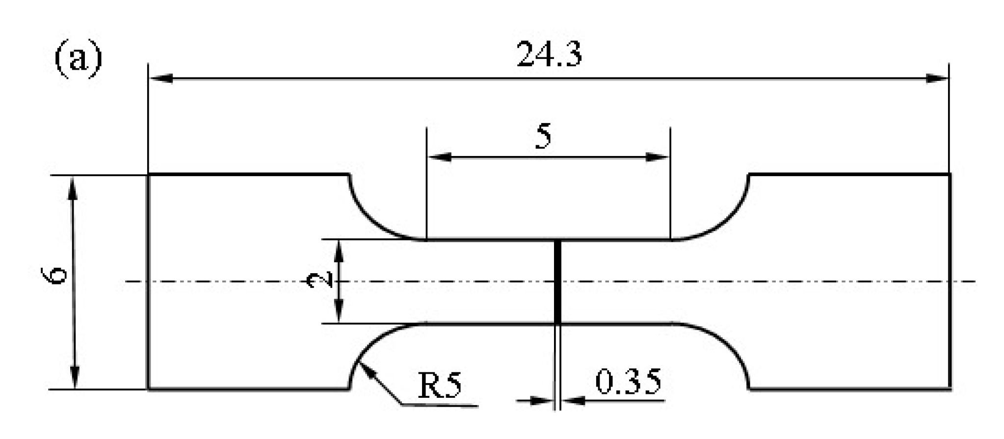
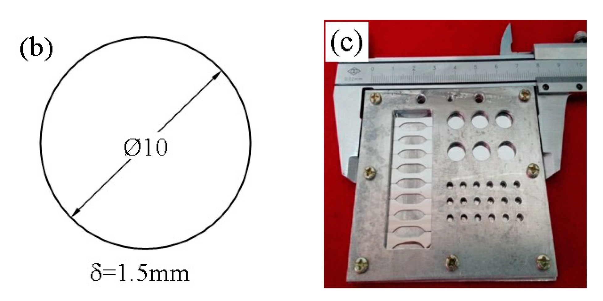
2.5.1. Tensile Test of the Irradiated Specimen
2.5.2. Nanoindentation Hardness Test of Irradiated Samples
2.6. TEM (Transmission Electron Microscope) and SEM (Scanning Electron Microscope) Analysis
3. Results
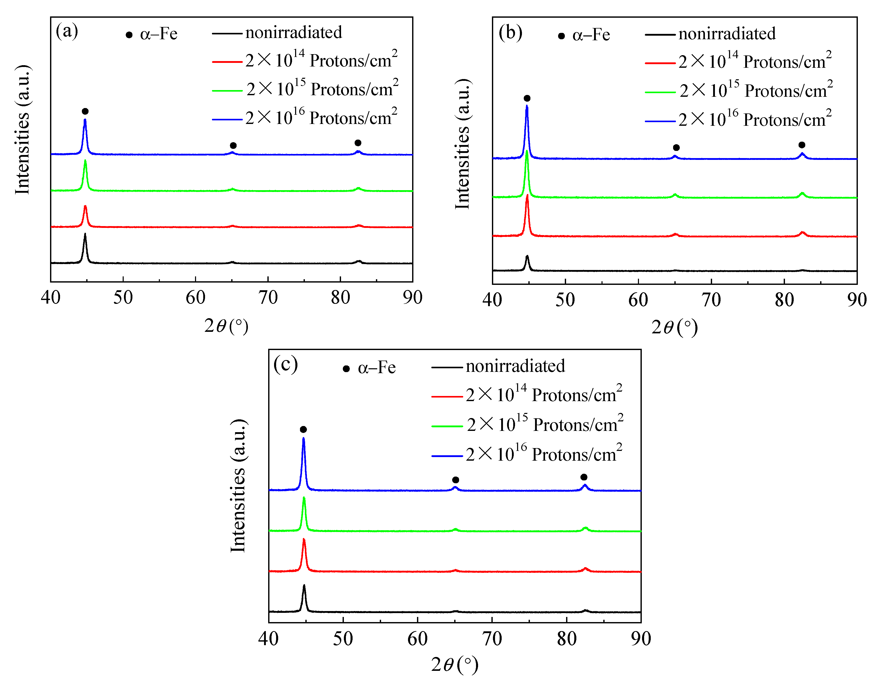
3.1. XRD
3.2. Simulation Results of Proton Irradiation Damage
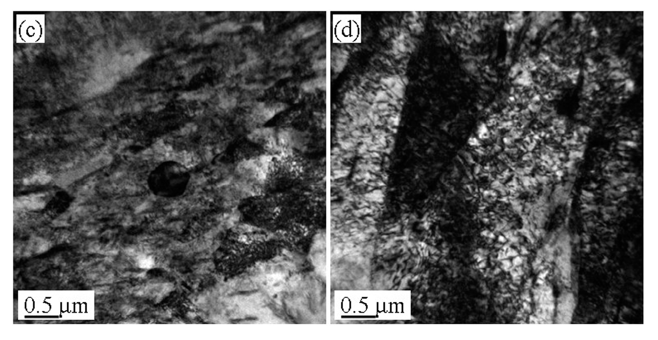
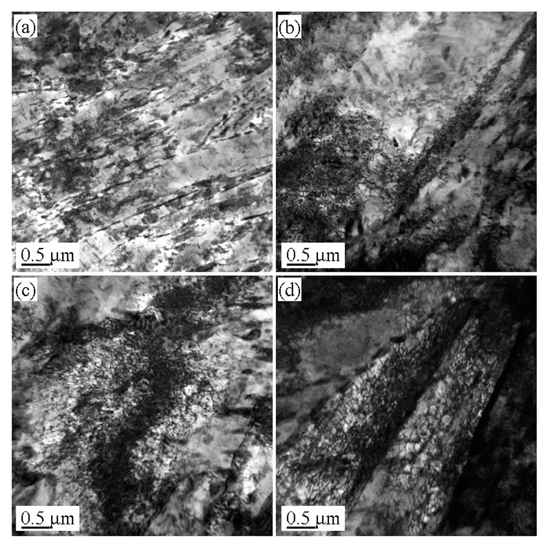
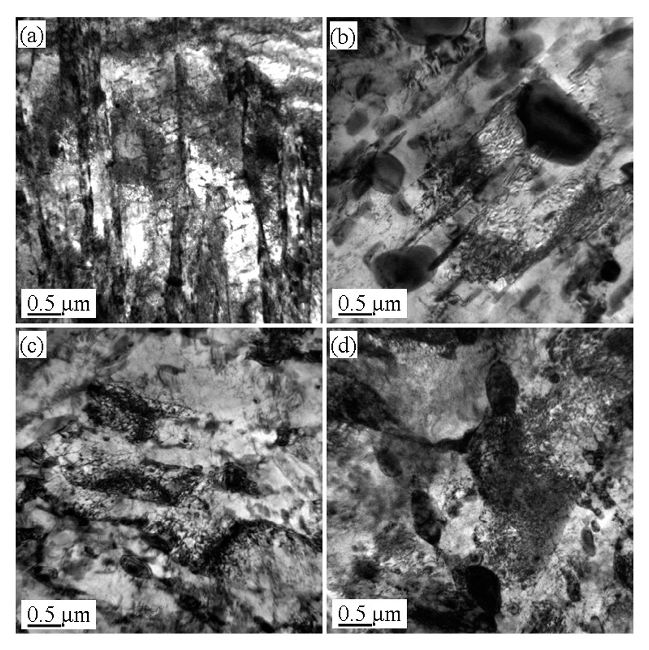
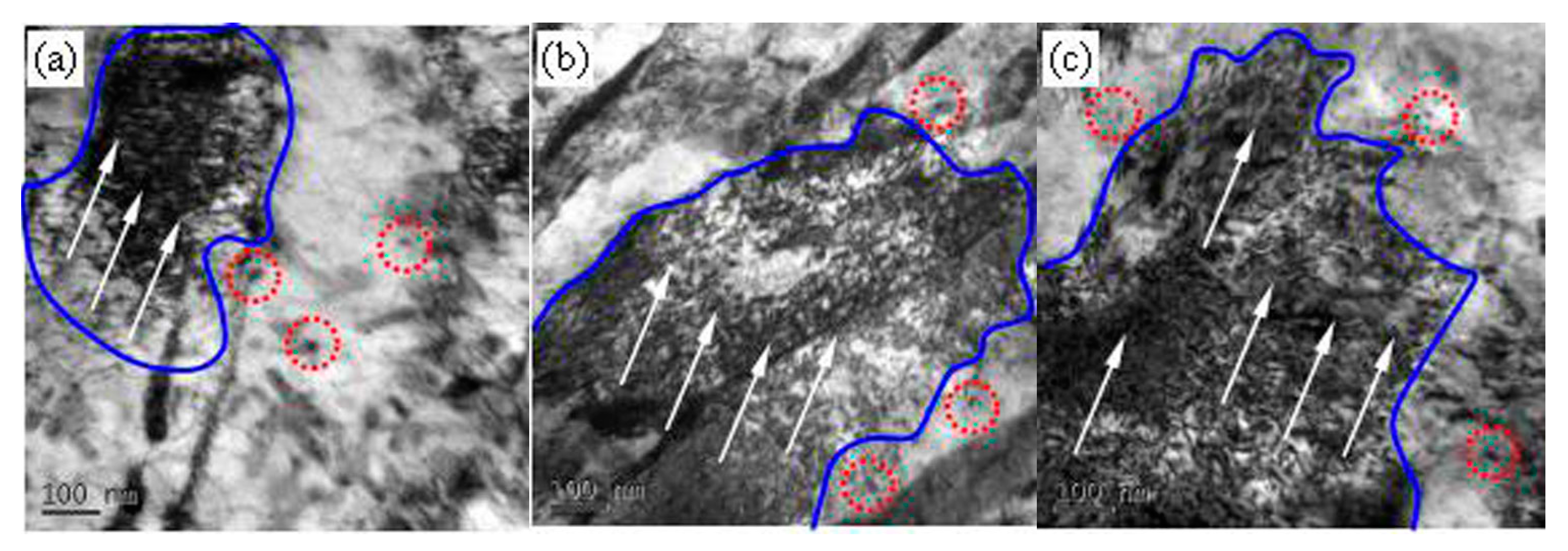
3.3. Microstructure Evolution of the Tempered 5140 Alloy Steel before and after Proton Irradiation
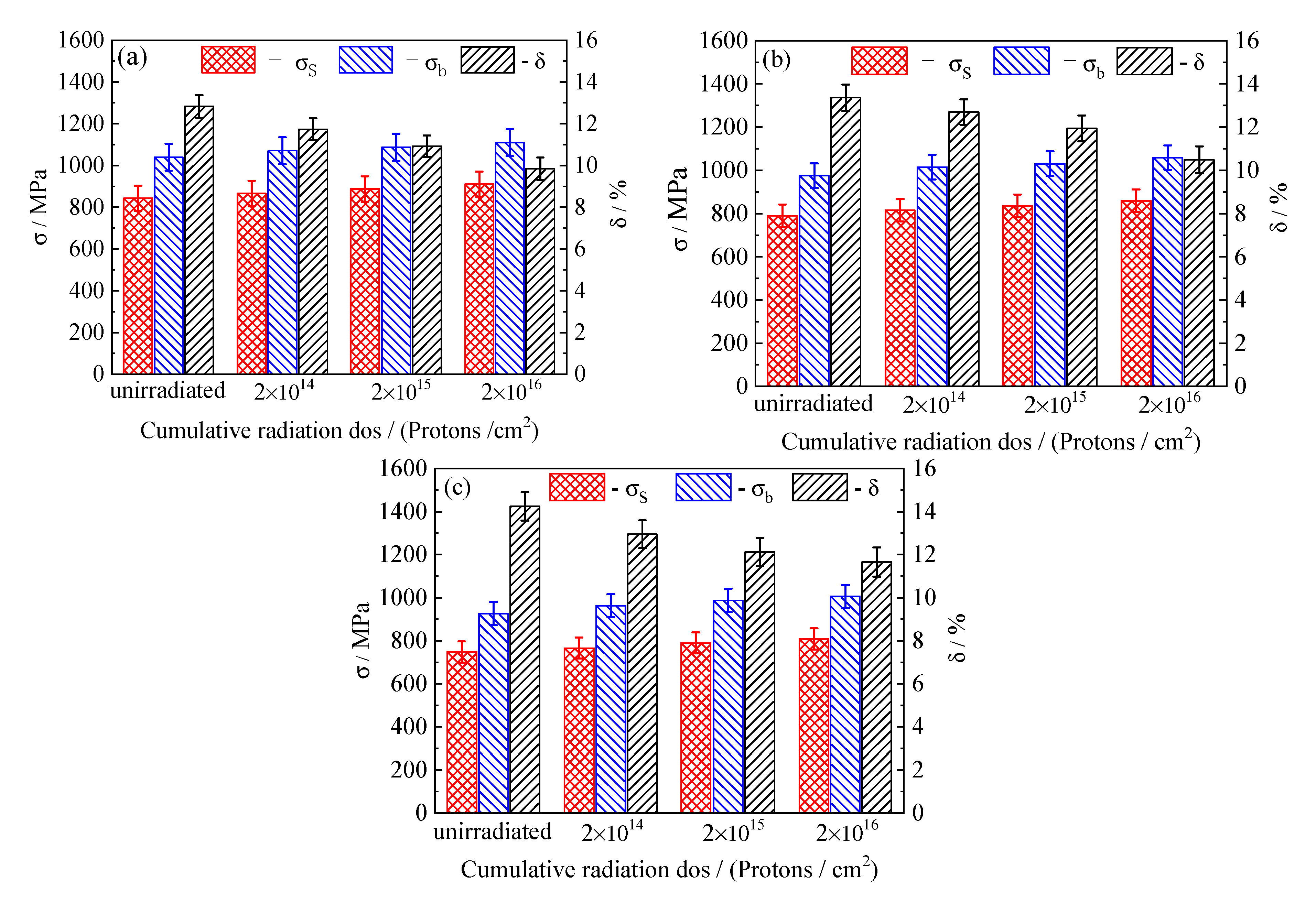
3.4. Macro Mechanical Properties of the Tempered 5140 Alloy Steel before and after Irradiation with Protons
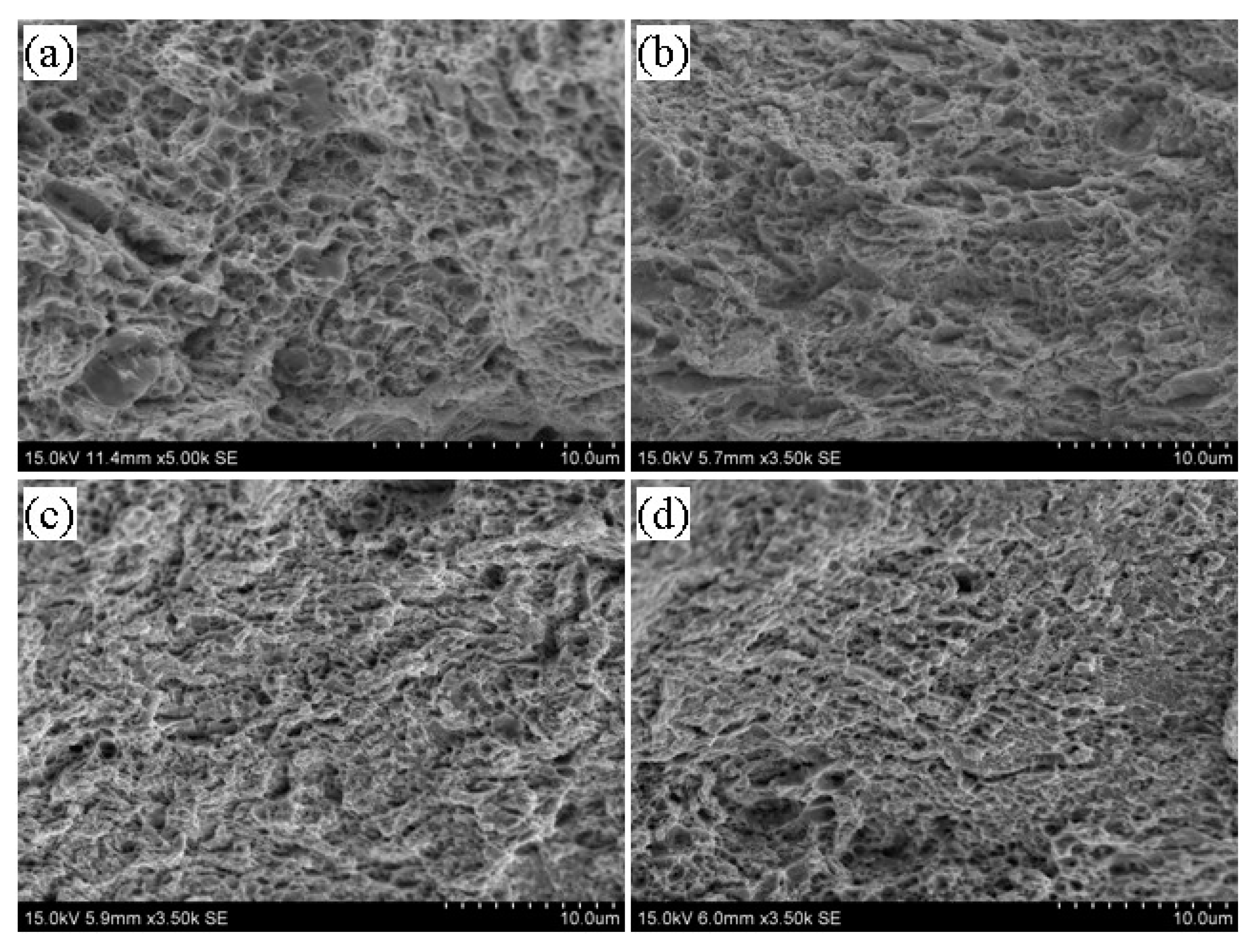
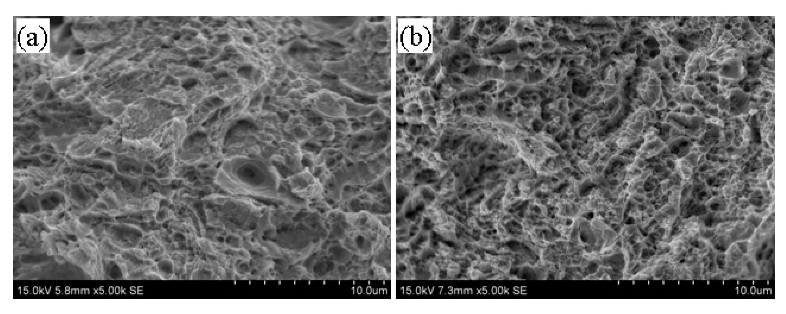
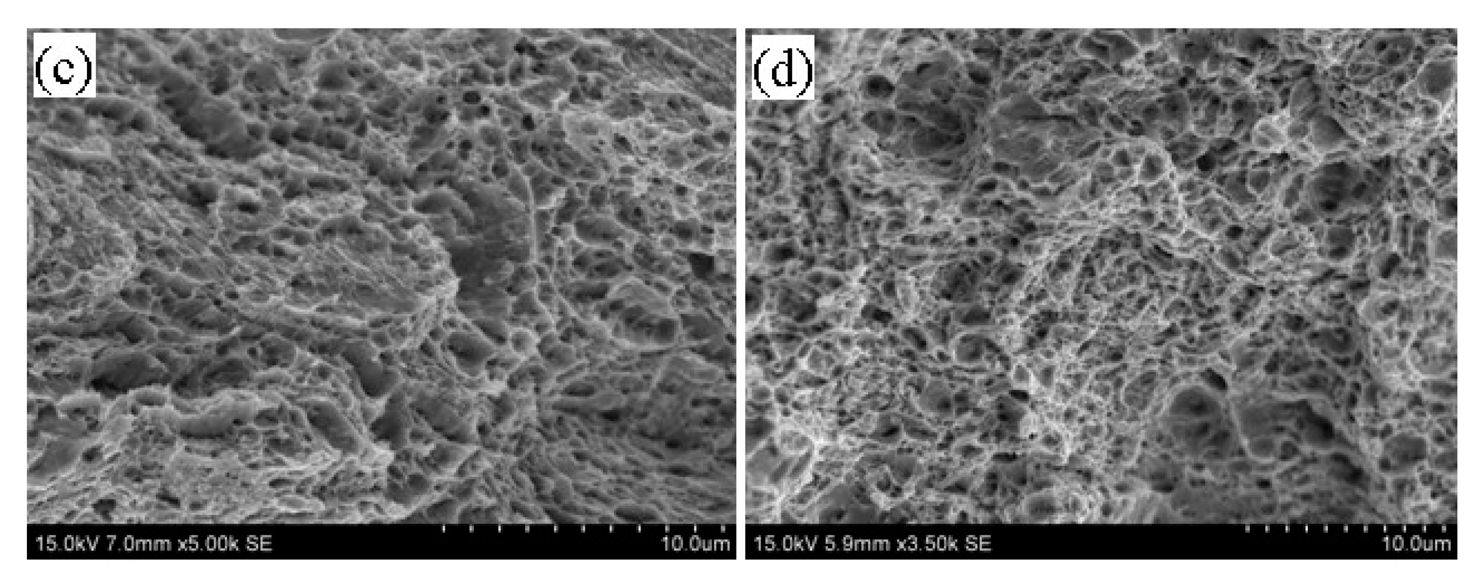
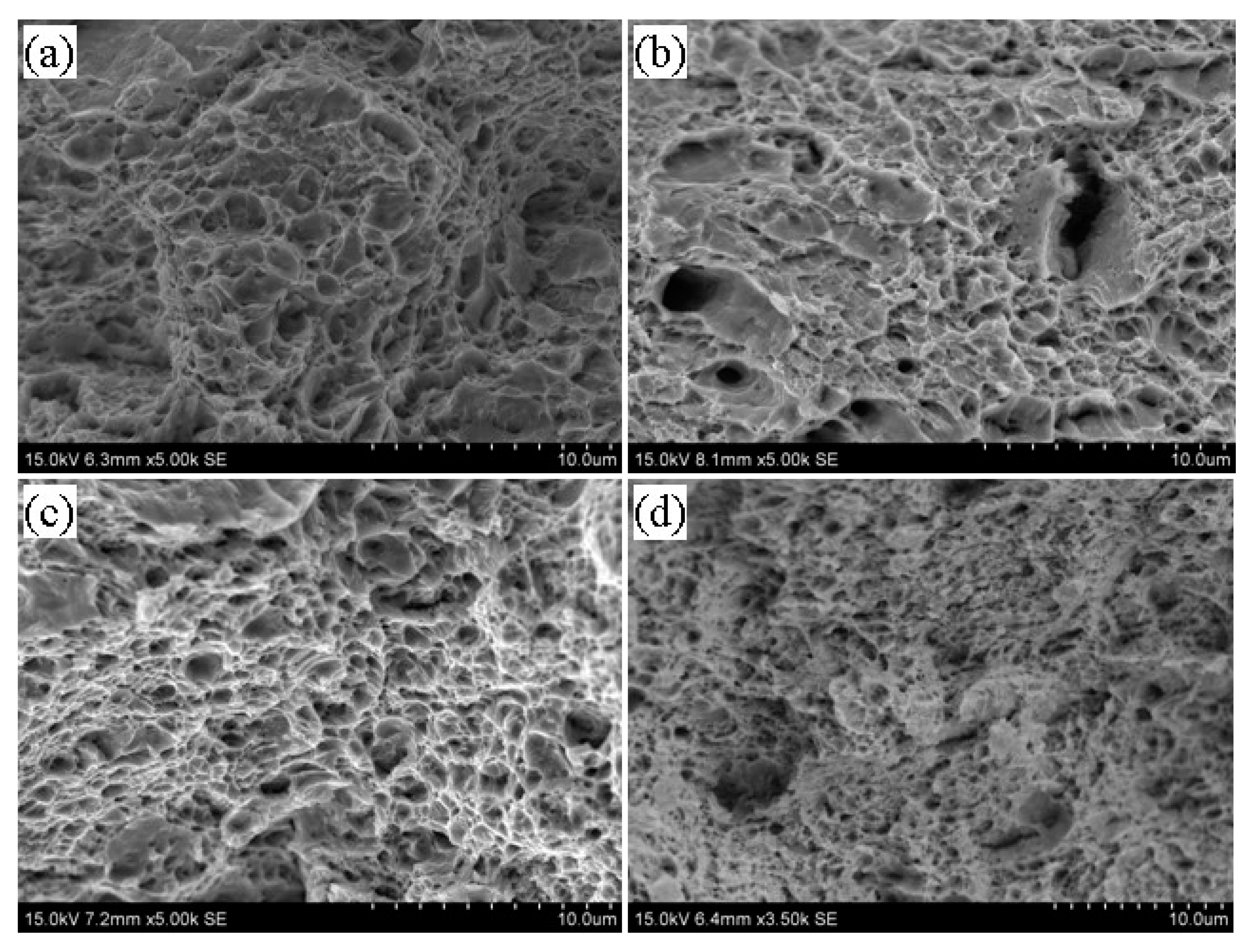
3.5. Tempering Fracture Morphology of 5140 Alloy Steel before and after Irradiation with Protons
3.6. Tempered Nanomechanical Properties of 5140 Alloy Steel before and after Proton Irradiation
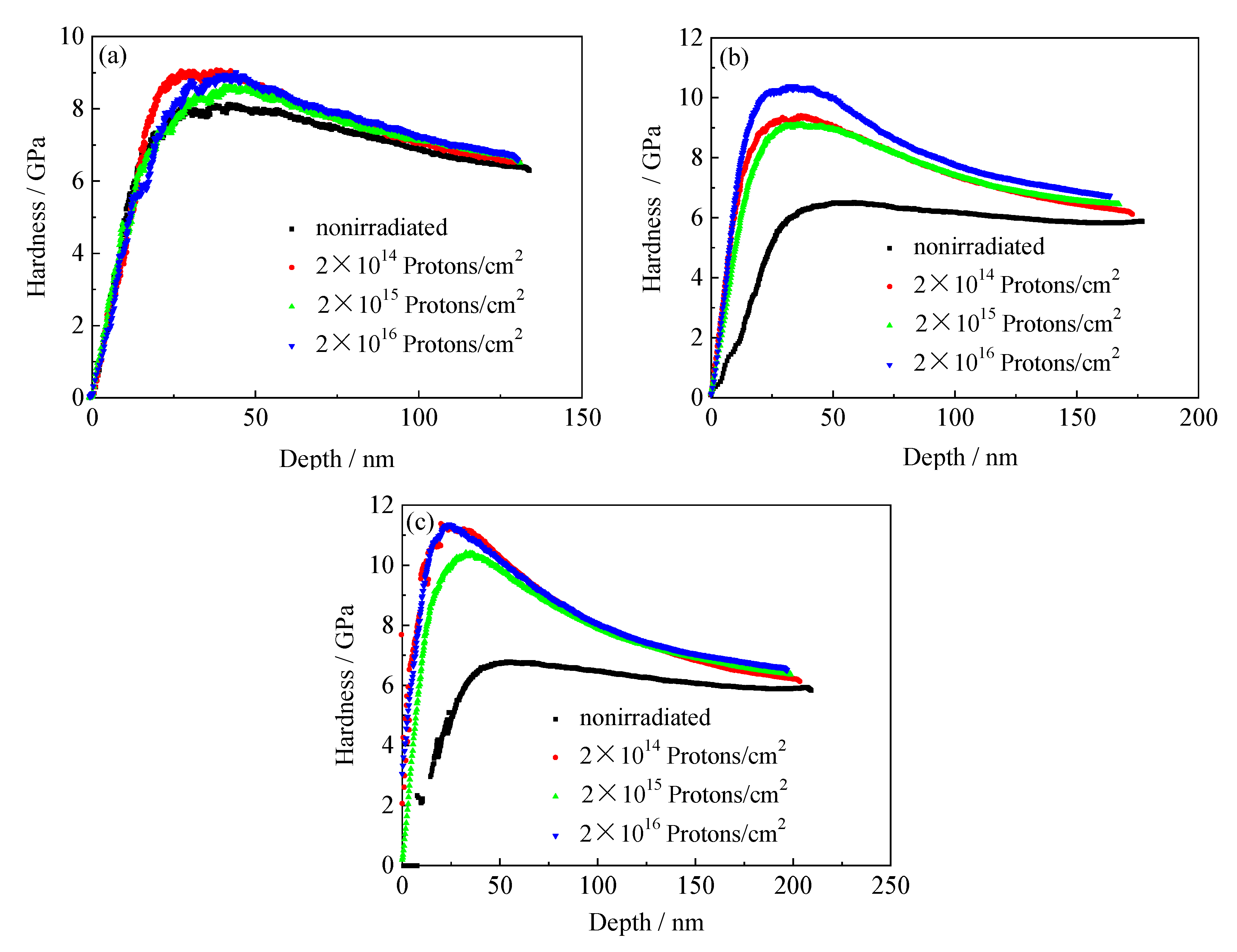
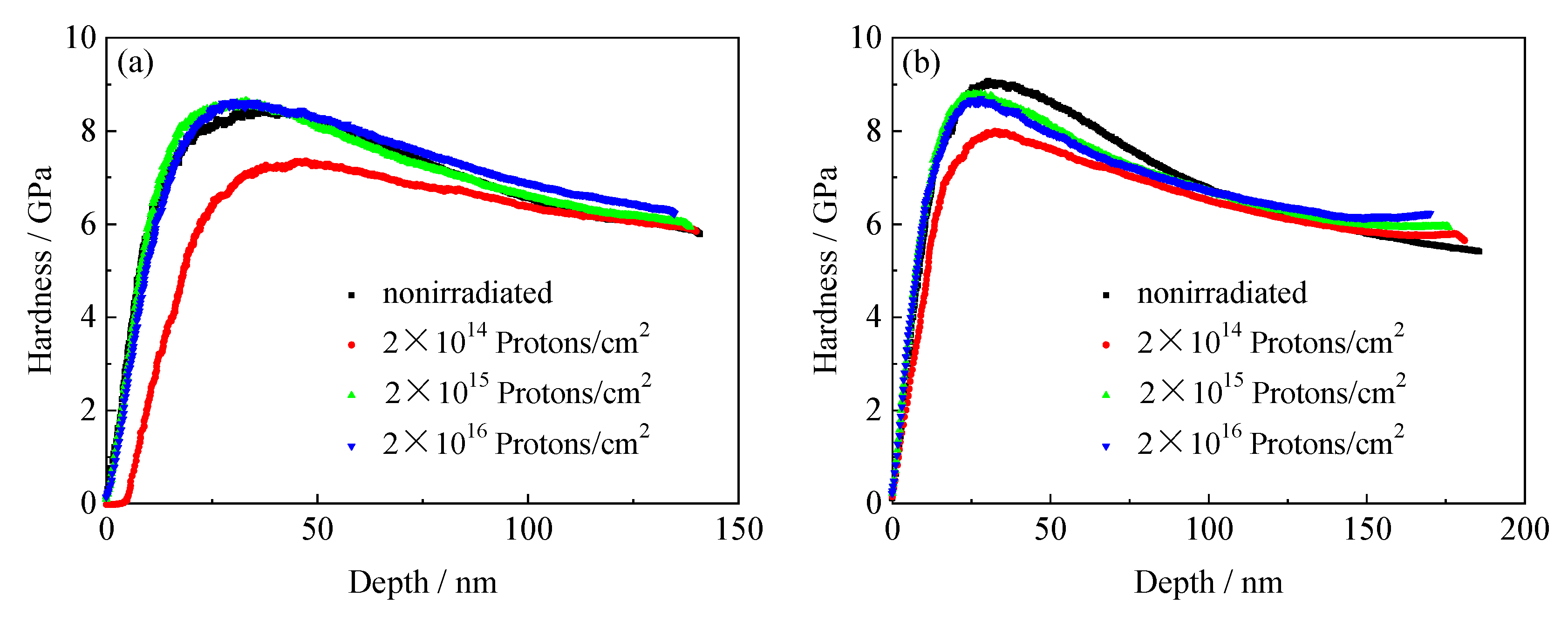
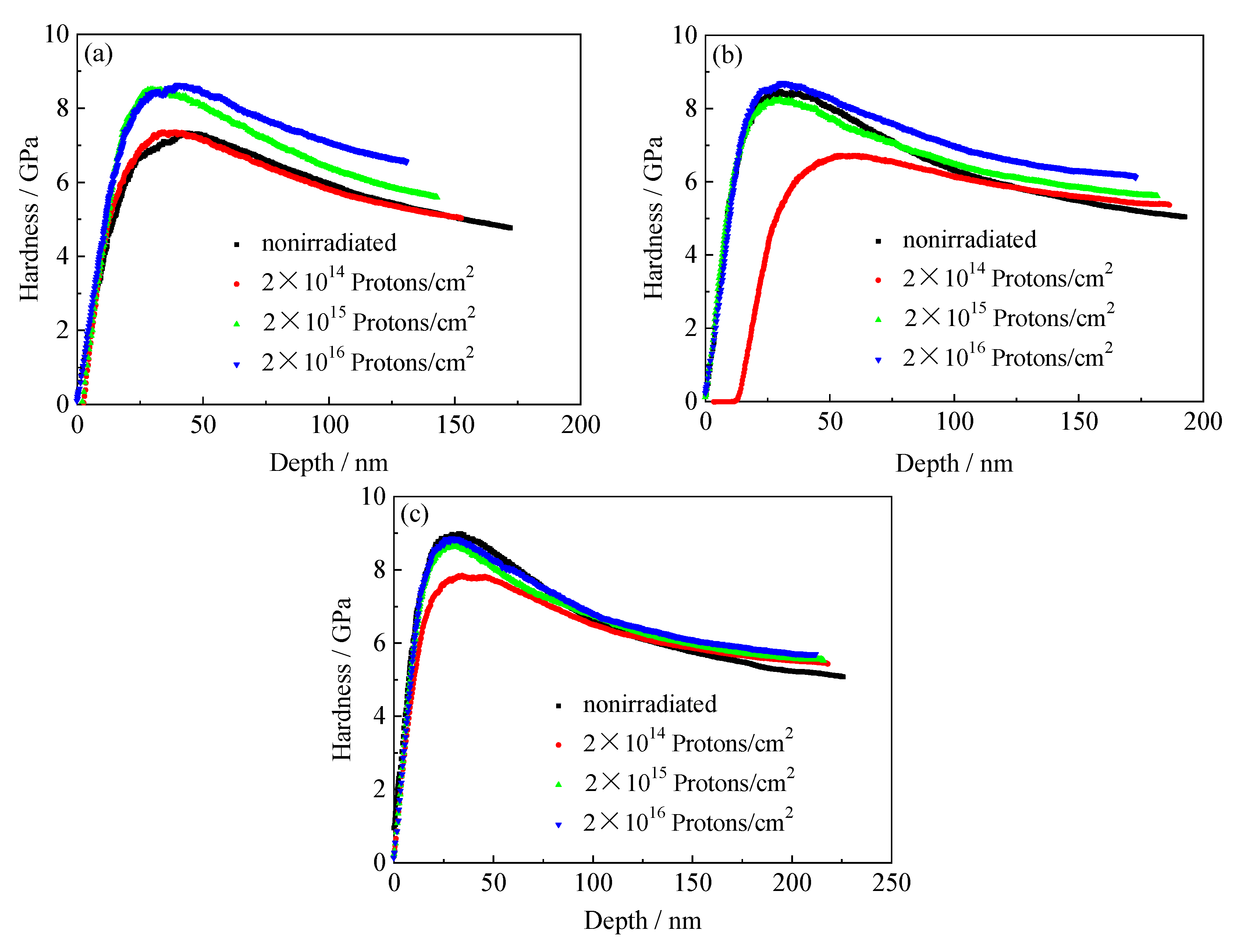
3.6.1. Nanoindentation Hardness and Depth Curves of the Tempered 5140 Alloy Steel before and after Irradiation with Protons
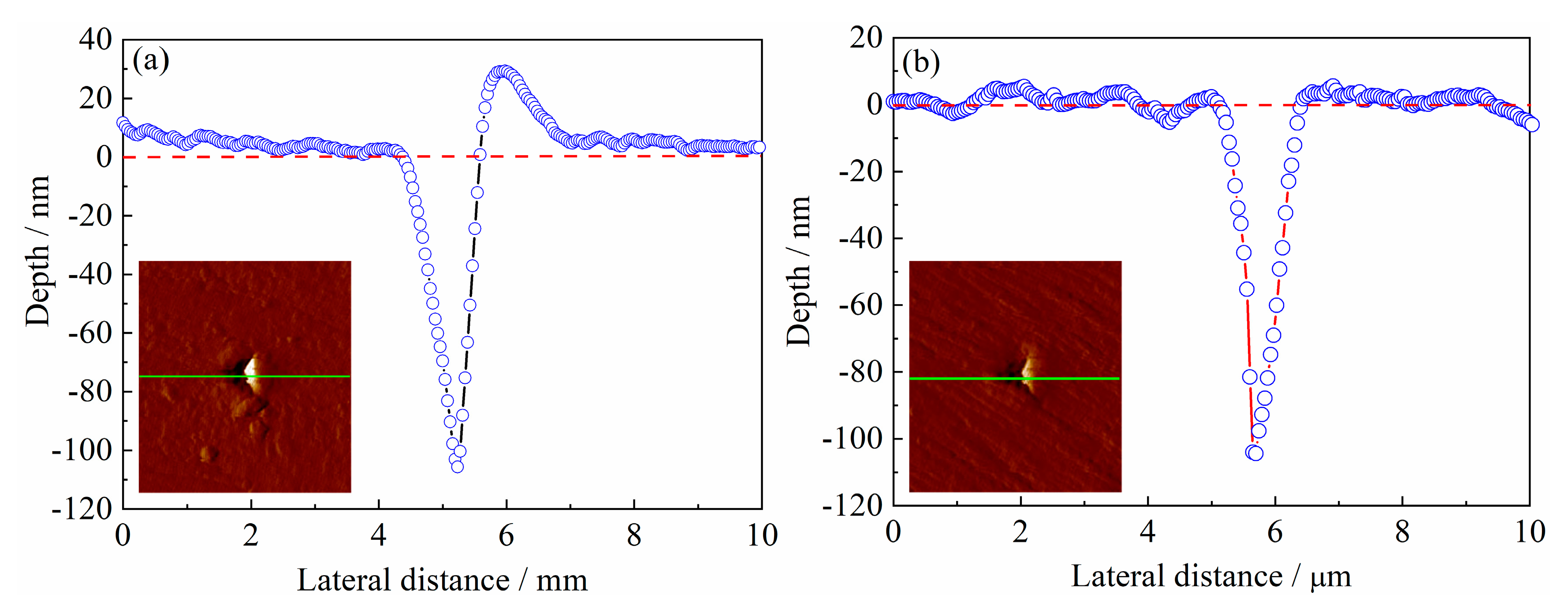
3.6.2. Nanomechanical Properties of the Tempered 5140 Alloy Steel before and after Irradiation with Protons
4. Discussion
4.1. Microstructure Evolution Mechanism of the Tempered 5140 Alloy Steel after the Proton Irradiation
4.2. Proton Irradiation Hardening Mechanism of Tempered 5140 Alloy Steel
5. Conclusions
Author Contributions
Funding
Conflicts of Interest
References
- Jiang, J.; Hu, J.; Yang, X.; Guo, N.; Xu, H.; Li, H.; Jin, Y.; Yu, H. Microstructure and annealing behavior of Cr-coatings deposited by double glow plasma on AISI 5140 steel. Results Phys. 2019, 15, 102674. [Google Scholar] [CrossRef]
- Zhao, X.; Zhang, H.; Liu, Y. Effect of laser surface remelting on the fatigue crack propagation rate of 40Cr steel. Results Phys. 2019, 12, 424–431. [Google Scholar] [CrossRef]
- Chen, L.; Sun, W.; Lin, J.; Zhao, G.; Wang, G. Modelling of constitutive relationship, dynamic recrystallization and grain size of 40Cr steel during hot deformation process. Results Phys. 2019, 12, 784–792. [Google Scholar] [CrossRef]
- Chen, H.; Liu, W.; Kong, D. Effect of Extrusion Temperatures on Friction-wear Behavior of Chain-wheel Fabricated by 40Cr Steel under Oil-lubrication Condition. J. Wuhan Univ. Technol. 2019, 34, 684–691. [Google Scholar] [CrossRef]
- Dong, H.G.; Yu, L.Z.; Deng, D.W. Effect of Post-Weld Heat Treatment on Properties of Friction Welded Joint between TC4 Titanium Alloy and 40Cr Steel Rods. J. Mater. Sci. Technol. 2015, 31, 962–968. [Google Scholar] [CrossRef]
- Shen, H.; Wang, L. Oxide layer formed on AISI 5140 steel by plasma nitriding and post-oxidation in a mixture of air and ammonia. J. Alloys Compd. 2019, 806, 1517–1521. [Google Scholar] [CrossRef]
- Dai, L.Y.; Niu, G.Y.; Ma, M.Z. Microstructure Evolution and Nanotribological Properties of Different Heat-Treated AISI 420 Stainless Steels after Proton Irradiation. Materials 2019, 12, 1736. [Google Scholar] [CrossRef] [Green Version]
- Was, G.S.; Allen, T.R.; Busby, J.T.; Gan, J.; Damcott, D.; Carter, D.; Atzmon, M.; Kenik, E.A. Microchemistry and microstructure of proton-irradiated austenitic alloys: Toward an understanding of irradiation effects in LWR core components. J. Nucl. Mater. 1999, 270, 96–114. [Google Scholar] [CrossRef]
- Was, G.S.; Busby, J.T.; Allen, T.; Kenik, E.A.; Jessen, A.; Bruemmer, S.M.; Gan, J.; Edwards, A.D.; Scott, P.M.; Andresen, P.L. Emulation of neutron irradiation effects with protons: Validation of principle. J. Nucl. Mater. 2002, 300, 198–216. [Google Scholar] [CrossRef]
- Jin, H.-H.; Hwang, S.S.; Choi, M.J.; Lee, G.-G.; Kwon, J. Proton irradiation for radiation-induced changes in microstructures and mechanical properties of austenitic stainless steel. J. Nucl. Mater. 2019, 513, 271–281. [Google Scholar] [CrossRef]
- Sencer, B.H.; Was, G.S.; Sagisaka, M.; Isobe, Y.; Bond, G.M.; Garner, F.A. Proton irradiation emulation of PWR neutron damage microstructures in solution annealed 304 and cold-worked 316 stainless steels. J. Nucl. Mater. 2003, 323, 18–28. [Google Scholar] [CrossRef]
- Stephenson, K.J.; Was, G.S. Comparison of the microstructure, deformation and crack initiation behavior of austenitic stainless steel irradiated in-reactor or with protons. J. Nucl. Mater. 2015, 456, 85–98. [Google Scholar] [CrossRef] [Green Version]
- Takeuchi, T.; Kuramoto, A.; Kameda, J.; Toyama, T.; Nagai, Y.; Hasegawa, M.; Ohkubo, T.; Yoshiie, T.; Nishiyama, Y.; Onizawa, K. Effects of chemical composition and dose on microstructure evolution and hardening of neutron-irradiated reactor pressure vessel steels. J. Nucl. Mater. 2010, 402, 93–101. [Google Scholar] [CrossRef]
- Zhu, Q.X.; Yang, M.M.; Zheng, M.; Wang, W.; Wang, Y.; Li, X.M.; Luo, H.S.; Li, X.G.; Chan, H.L.W.; Zheng, R.K. The strain effect and the ferroelectric field effect in LaMnO3+δ film/Pb(Mg1/3Nb2/3)O3–PbTiO3 single-crystal heterostructures. J. Alloys Compd. 2013, 581, 530–533. [Google Scholar] [CrossRef]
- Wan, Q.M.; Shu, G.G.; Wang, R.S.; Ding, H.; Peng, X.; Zhang, Q.; Lei, J. Characterization of proton irradiation-induced defect in the A508-3 steel by slow positron beam. Nucl. Instrum. Methods B 2012, 287, 148–152. [Google Scholar]
- Lambrecht, M.; Almazouzi, A. Positron annihilation study of neutron irradiated model alloys and of a reactor pressure vessel steel. J. Nucl. Mater. 2009, 385, 334–338. [Google Scholar] [CrossRef]
- Watanabe, H.; Masaki, S.; Masubuchi, S.; Yoshida, N.; Kamada, Y. Radiation induced hardening of ion irradiated RPV steels. J. Nucl. Mater. 2011, 417, 932–935. [Google Scholar] [CrossRef]
- Hernandez-Mayoral, M.; Gomez-Briceno, D. Transmission electron microscopy study on neutron irradiated pure iron and RPV model alloys. J. Nucl. Mater. 2010, 399, 146–153. [Google Scholar] [CrossRef]
- Fujii, K.; Fukuya, K. Characterization of defect clusters in ion-irradiated A533B steel. J. Nucl. Mater. 2005, 336, 323–330. [Google Scholar] [CrossRef]
- Gupta, J.; Hure, J.; Tanguy, B.; Laffont, L.; Lafont, M.C.; Andrieu, E. Characterization of ion irradiation effects on the microstructure, hardness, deformation and crack initiation behavior of austenitic stainless steel: Heavy ions vs protons. J. Nucl. Mater. 2018, 501, 45–58. [Google Scholar] [CrossRef] [Green Version]
- Zinkle, S.J.; Maziasz, P.J.; Stoller, R.E. Dose dependence of the microstructural evolution in neutron-irradiated austenitic stainless steel. J. Nucl. Mater. 1993, 206, 266–286. [Google Scholar] [CrossRef]
- Pokor, C.; Brechet, Y.; Dubuisson, P.; Massoud, J.P.; Averty, X. Irradiation damage in 304 and 316 stainless steels: Experimental investigation and modeling. Part II: Irradiation induced hardening. J. Nucl. Mater. 2004, 326, 30–37. [Google Scholar] [CrossRef]
- Etienne, A.; Hernandez-Mayoral, M.; Genevois, C.; Radiguet, B.; Pareige, P. Dislocation loop evolution under ion irradiation in austenitic stainless steels. J. Nucl. Mater. 2010, 400, 56–63. [Google Scholar] [CrossRef]
- National Standards of the People’s Republic of China. Alloy Structure Steels, GB/T 3077-1999; Standards Press of China: Beijing, China, 2000; Volume 1, p. 9. (In Chinese) [Google Scholar]
- National Standards of the People’s Republic of China. Metallic Materials-Tensile Testing at Ambient Temperature, GB/T 228-2002; Standards Press of China: Beijing, China, 2002; Volume 3, pp. 16–18. (In Chinese) [Google Scholar]
- Ward, J.; Middleburgh, S.; Topping, M.; Garner, A.; Stewart, D.; Barsoum, M.W.; Preuss, M.; Frankel, P. Crystallographic evolution of MAX phases in proton irradiating environments. J. Nucl. Mater. 2018, 502, 220–227. [Google Scholar] [CrossRef] [Green Version]
- Hug, E.; Babu, R.P.; Monnet, I.; Etienne, A.; Moisy, F.; Pralong, V.; Enikeev, N.; Abramova, M.; Sauvage, X.; Radiguet, B. Impact of the nanostructuration on the corrosion resistance and hardness of irradiated 316 austenitic stainless steels. Appl. Surf. Sci. 2017, 392, 1026–1035. [Google Scholar] [CrossRef]
- Hosemann, P.; Swadener, J.G.; Kiener, D.; Was, G.S.; Maloy, S.A.; Li, N. An exploratory study to determine applicability of nano-hardness and micro-compression measurements for yield stress estimation. J. Nucl. Mater. 2008, 375, 135–143. [Google Scholar] [CrossRef]
- Wan, Q.M.; Shu, G.G.; Wang, R.S.; Ding, H.; Peng, X.; Zhang, Q.; Lei, J. Study on the Microstructure evolution of A508–3 Steel under Proton Irradiarion. Acta Metall. Sin. 2012, 48, 929–934. [Google Scholar] [CrossRef]
- Nix, W.D.; Gao, H.J. Indentation size effects in crystalline materials: A law for strain gradient plasticity. J. Mech. Phys. Solids. 1998, 46, 411–425. [Google Scholar] [CrossRef]
- Janni, J.F. Energy loss, range, path length, time-of-flight, straggling, multiple scattering, and nuclear interaction probability: In two parts. Part 1. For 63 compounds Part 2. For elements 1 Z 92. Atomic Data Nucl. Data 1982, 27, 147–339. [Google Scholar] [CrossRef]
- Zhang, Z.W.; Liu, C.T.; Wang, X.L.; Miller, M.K.; Ma, D.; Chen, G.; Williams, J.R.; Chin, B.A. Effects of proton irradiation on nanocluster precipitation in ferritic steel containing fcc alloying additions. Acta Mater. 2012, 60, 3034–3046. [Google Scholar] [CrossRef]
- Zheng, C.; Auger, M.A.; Moody, M.P.; Kaoumi, D. Radiation induced segregation and precipitation behavior in self-ion irradiated Ferritic/Martensitic HT9 steel. J. Nucl. Mater. 2017, 491, 162–176. [Google Scholar] [CrossRef]
- Dai, Y.; Henry, J.; Tong, Z.; Averty, X.; Malaplate, J.; Long, B. Neutron/proton irradiation and He effects on the microstructure and mechanical properties of ferritic/martensitic steels T91 and EM10. J. Nucl. Mater. 2011, 415, 306–310. [Google Scholar] [CrossRef]
- Henry, J.; Averty, X.; Alamo, A. Tensile and impact properties of 9Cr tempered martensitic steels and ODS-FeCr alloys irradiated in a fast reactor at 325 °C up to 78 dpa. J. Nucl. Mater. 2011, 417, 99–103. [Google Scholar] [CrossRef]
- Yabuuchi, K.; Kuribayashi, Y.; Nogami, S.; Kasada, R.; Hasegawa, A. Evaluation of irradiation hardening of proton irradiated stainless steels by nanoindentation. J. Nucl. Mater. 2014, 446, 142–147. [Google Scholar] [CrossRef]
- Ma, Y.Z.; Ran, G.; Chen, N.J.; Lei, P.H.; Shen, Q. Investigation of mechanical properties and proton irradiation behaviors of SA-738 Gr.B steel used as reactor containment. Nucl. Mater. Energy 2016, 8, 18–22. [Google Scholar] [CrossRef] [Green Version]
- Sencer, B.H.; Bond, G.M.; Hamilton, M.L.; Garner, F.A.; Maloy, S.A.; Sommer, W.F. Microstructural origins of radiation-induced changes in mechanical properties of 316 L and 304 L austenitic stainless steels irradiated with mixed spectra of high-energy protons and spallation neutrons. J. Nucl. Mater. 2001, 296, 112–118. [Google Scholar] [CrossRef]
- Alshater, A.F.; Engelberg, D.L.; Donohoe, C.J.; Lyon, S.B.; Sherry, A.H. Proton irradiation damage in cold worked Nb-stabilized 20Cr-25Ni stainless steel. Appl. Surf. Sci. 2018, 454, 130–137. [Google Scholar] [CrossRef]


| Materials | C | Mn | Si | S | P | Ni | Cr | Cu | Fe |
|---|---|---|---|---|---|---|---|---|---|
| 5140 alloy steel | 0.42 | 0.66 | 0.26 | 0.006 | 0.009 | 0.01 | 0.98 | 0.01 | other |
| Pressure Load μN | Irradiation Dose Protons/cm2 | Tempering Temperature | ||||||||
|---|---|---|---|---|---|---|---|---|---|---|
| 480 °C | 520 °C | 560 °C | ||||||||
| E GPa | H GPa | D nm | E GPa | H GPa | D nm | E GPa | H GPa | D nm | ||
| 4000 | 0 | 211.9 | 6.29 | 133.9 | 209.2 | 5.79 | 140.6 | 208.7 | 4.76 | 172.1 |
| 2 × 10¹⁴ | 209.6 | 6.54 | 130.7 | 210.0 | 5.85 | 139.9 | 207.6 | 5.03 | 152.5 | |
| 2 × 10¹⁵ | 212.6 | 6.56 | 130.5 | 211.7 | 5.96 | 138.7 | 209.0 | 5.59 | 142.9 | |
| 2 × 10¹⁶ | 211.1 | 6.58 | 130.3 | 208.4 | 6.23 | 134.6 | 206.5 | 6.54 | 130.8 | |
| 6000 | 0 | 205.8 | 5.87 | 176.9 | 203.9 | 5.41 | 185.5 | 202.1 | 5.04 | 192.4 |
| 2 × 10¹⁴ | 206.1 | 6.12 | 172.8 | 205.2 | 5.68 | 180.5 | 203.1 | 5.38 | 186.1 | |
| 2 × 10¹⁵ | 206.1 | 6.45 | 167.4 | 206.3 | 5.93 | 175.9 | 202.2 | 5.61 | 181.6 | |
| 2 × 10¹⁶ | 207.4 | 6.72 | 163.6 | 205.2 | 6.23 | 170.1 | 203.2 | 6.15 | 172.3 | |
| 8000 | 0 | 202.5 | 5.87 | 208.6 | 200.9 | 4.93 | 229.9 | 198.7 | 5.08 | 224.9 |
| 2 × 10¹⁴ | 203.5 | 6.13 | 203.4 | 201.0 | 5.39 | 217.6 | 200.9 | 5.43 | 217.9 | |
| 2 × 10¹⁵ | 203.0 | 6.37 | 198.8 | 202.8 | 5.81 | 211.9 | 199.3 | 5.56 | 215.1 | |
| 2 × 10¹⁶ | 204.1 | 6.51 | 196.7 | 203.3 | 6.22 | 201.9 | 201.9 | 5.69 | 211.9 | |
© 2020 by the authors. Licensee MDPI, Basel, Switzerland. This article is an open access article distributed under the terms and conditions of the Creative Commons Attribution (CC BY) license (http://creativecommons.org/licenses/by/4.0/).
Share and Cite
Dai, L.; Niu, G.; Ma, M. Microstructure Evolution and Mechanical Properties of Tempered 5140 Alloy Steel after Proton Irradiation at Different Temperatures. Materials 2020, 13, 2910. https://doi.org/10.3390/ma13132910
Dai L, Niu G, Ma M. Microstructure Evolution and Mechanical Properties of Tempered 5140 Alloy Steel after Proton Irradiation at Different Temperatures. Materials. 2020; 13(13):2910. https://doi.org/10.3390/ma13132910
Chicago/Turabian StyleDai, Luanyue, Guangyi Niu, and Mingzhen Ma. 2020. "Microstructure Evolution and Mechanical Properties of Tempered 5140 Alloy Steel after Proton Irradiation at Different Temperatures" Materials 13, no. 13: 2910. https://doi.org/10.3390/ma13132910