Dynamic Tensile Stress-Compressive Stress Behavior of Thermoplastic Matrix Composite Materials Reinforced with Continuous Fiber for Automotive Damping and Anti-Vibration Structural Elements


Abstract
1. Introduction
2. Materials and Methods
- –
- ASTM D3039/D3039M—08 “Standard Test Method for Tensile Properties of Polymer Matrix Composite Materials” [33].
- –
- ISO 527-4: 1997—“Plastics-Determination of tensile properties—Part 4: Test conditions for isotropic and orthotropic fiber-reinforced plastic composites. And its transposition to the European Union and the States that compose it, e.g., Spain (UNE-EN-ISO 527-4)” [34].
- “Thermoplastic and thermosetting compounds reinforced with fibers that incorporate non-unidirectional reinforcements such as felts, fabrics (flat or windings), cut threads, combinations of these reinforcements, hybrids, windings, short or ground fibers or pre-impregnated materials (“prepregs”), using test pieces molded directly by injection” (ISO 527-1: 1993) [35].
- “Combinations of the above with unidirectional or multidirectional reinforcements, constructed from unidirectional layers, provided that such laminates are symmetrical for materials with full or mainly unidirectional reinforcements” (ISO 527-5) [36].
- Reinforced fibers, fiberglass, carbon, aramid, and other similar fibers.
- Finished products obtained from these materials.
3. Results
4. Discussion
- The stiffness of CFRTP reinforced was 60% lower than steel (Figure 13).
- The damping angle of CFRTP was greater than steel at any frequency and amplitude.
- The CFRTPs did not come into resonance under any circumstances.
Future Investigations
5. Conclusions
- These materials are more flexible than those currently used, such as steel or aluminum, allowing deformation in the event of a collision and absorbing more energy. In this way, the accelerations to which passengers are subjected are lower.
- They are more resistant to deformation, which makes it possible to avoid the penetration of any part of the vehicle into the security cabin, reducing the risk of injury to passengers. Thermoplastics have greater impact resistance than thermosets.
- These materials are lighter than the materials currently used. By reducing the weight, the power generated by the engine needed to move the vehicle will be lower, reducing fuel consumption and, thereby, reducing emissions of polluting gases into the atmosphere.
- Great capacity of absorption of the vibrations and noises is generated mainly by the engine, mechanical parts, wind, and disturbances of the road.
- High capacity of processing CFRTP materials offers very low production times as they can be processed automatically by thermoforming, unlike thermosetting matrix composites.
- Capability to be easily recycled, unlike their counterparts thermosetting composites, and have a greater advantage over steels.
Author Contributions
Funding
Acknowledgments
Conflicts of Interest
References
- European Commission. Available online: http://ec.europa.eu (accessed on 5 November 2019).
- Reducing CO2 Emissions from Passenger Cars. Available online: https://ec.europa.eu/clima/policies/transport/vehicles/cars_en (accessed on 5 November 2019).
- Environment Council. Available online: https://www.consilium.europa.eu/en/meetings/env/ (accessed on 25 October 2019).
- Cálculo de la HC y Análisis del Reciclado de Vehículos. Available online: https://seguridadypromociondelasalud.fundacionmapfre.org/n131/es/articulo3.html (accessed on 5 November 2019).
- Resource-Efficient Production Trends. European Automobile Manufacturers, Association-ACEA. Available online: https://www.acea.be/statistics/tag/category/resource-efficient-production-trends (accessed on 5 November 2019).
- Materials Group. University Cambridge. Available online: http://www-materials.eng.cam.ac.uk (accessed on 5 November 2019).
- Martin, A.M. Introduction of Fibre-Reinforced Polymers-Polymers & Composites: Concepts, Properties and Processes. In Fiber Reinforced Polymers-The Technology Applied for Concrete Repair; Intech Open: London, UK, 2013; pp. 4–40. [Google Scholar] [CrossRef]
- Thije, R.H.; Akkerman, A. Multi-layer triangular membrane finite element for the forming simulation of laminated composite. Compos. Part A 2009, 40, 739–753. [Google Scholar]
- Stewart, R. Thermoplastic composites-recyclable and fast to process. Reinf. Plast. 2011, 55, 22–28. [Google Scholar] [CrossRef]
- Bing, L.; Peng, Z.; Anchang, X. Investigation of the recycling of continuous fiber-reinforced thermoplastics. J. Thermoplast. Compos. Mater. 2018, 32, 342–356. [Google Scholar]
- Nishida, H.; Carvelli, V.; Fujii, T.; Okubo, K. Thermoplastic vs. thermoset epoxy carbon textile composites. In IOP Conference Series Materials Science and Engineering; IOP Publishing: Milano, Italy, 2018. [Google Scholar] [CrossRef]
- SEAM Project—R&D EU Projects. Available online: http://www.seam-cluster.eu/ (accessed on 5 November 2019).
- ALIVE Project—R&D EU Projects. Available online: http://www.project-alive.eu/ (accessed on 5 November 2019).
- Gibson, R.F.; Plunkett, R. Dynamic Mechanical Behavior of Fiber-Reinforced Composites: Measurement and Analysis. J. Compos. Mater. 1976, 10, 325–341. [Google Scholar] [CrossRef]
- Gibson, R.F.; Wilson, D.G. Dynamic mechanical properties of fiber-reinforced composite materials. In Shock and Vibration Diges; SAGE: Newbury Park, CA, USA, 1979. [Google Scholar]
- Adams, R.D.; Bacon, D.G.C. Effect of fiber orientation and laminate geometry on the Dynamic properties of CFRP. J. Compos. Mater. 1973, 7, 402–428. [Google Scholar] [CrossRef]
- Ni, R.G.; Adams, R.D. The damping and dynamic moduli of symmetric laminated composite beams. Theoretical and experimental results. J. Compos. Mater. 1984, 18, 104–121. [Google Scholar] [CrossRef]
- Lin, D.X.; Ni, R.; Adams, R.D. Prediction and measurement of the vibrational parameters of carbon and glass-fiber reinforced plastic plates. J. Compos. Mater. 1984, 18, 132–152. [Google Scholar] [CrossRef]
- Maheri, M.R.; Adams, R.D. Finite element prediction of modal response of damped layered composite panels. Compos. Sci. Technol. 1995, 55, 13–23. [Google Scholar] [CrossRef]
- Vinson, J.R.; Sierakowski, R.L. The Behavior of Structures Composed of Composite Materials; Martinus, N., Ed.; Kluwer Academic Publisher: Dordrecht, The Netherlands, 1986. [Google Scholar]
- Atsushi, H.; Hiroyuki, K. Fatigue Life Prediction for Transverse Crack Initiation of CFRP Cross Ply and Quasi-Isotropic Laminates. Materials 2018, 11, 1182. [Google Scholar] [CrossRef]
- Adams, R.D.; Maheri, M.R. Dynamic flexural properties of anisotropic fibrous composite beams. Compos. Sci. Technol. 1994, 50, 497–514. [Google Scholar] [CrossRef]
- Berthelot, J.M.; Sefrani, Y. Damping analysis of unidirectional glass and Kevlar fibre composites. Compos. Sci. Technol. 2004, 64, 1261–1278. [Google Scholar] [CrossRef]
- Taniguchi, N.; Nishiwaki, T.; Hirayama, N.; Nishida, H.; Kawada, H. Dynamic tensile properties of carbon fiber composite based on thermoplastic epoxy resin loaded in matrix-dominant directions. Compos. Sci. Technol. 2009, 69, 207–213. [Google Scholar] [CrossRef]
- Yim, J.H.; Gillespie, J.W., Jr. Damping characteristics of 0° and 90° AS4/3501-6 unidirectional laminates including the transverse shear effect. Compos. Struct. 2000, 50, 217–225. [Google Scholar] [CrossRef]
- Ohta, Y.; Narita, Y.; Nagasaki, K. On the damping analysis of FRP laminated composite plates. Compos. Struct. 2002, 57, 169–175. [Google Scholar] [CrossRef]
- Sahoo, R.; Singh, B.N. Assessment of dynamic instability of laminated composite sandwich plates. Aerosp. Sci. Technol. 2018, 81, 41–52. [Google Scholar] [CrossRef]
- Gomez-del Rio, T.; Barbero, E.; Zaera, R.; Navarro, C. Dynamic tensile behaviour at low temperature of CFRP using a split Hopkinson pressure bar. Compos. Sci. Technol. 2005, 65, 61–71. [Google Scholar] [CrossRef]
- Tobalina-Baldeón, D.; Sanz-Adan, F. Characterization of an adhesive bonding between Continuous Fiber-Reinforced Thermoplastic (CFRTP) composites and vulcanized rubber under a shear load case study. DYNA 2019, 94, 226–232. [Google Scholar] [CrossRef]
- Tobalina, D.; Sanz-Adan, F.; Lostado-Lorza, R.; Martínez-Calvo, M.; Santamaría-Peña, J.; Sanz-Peña, I. Characterization of a Composite Material Reinforced with Vulcanized Rubber. In Advances on Mechanics, Design, Engineering and Manufacturing; Eynard, B., Nigrelli, V., Oliveri, S., Peris-Fajarnes, G., Rizzuti, S., Eds.; Springer: Cham, Swizerland, 2017; pp. 1073–1082. [Google Scholar] [CrossRef]
- ASTM A29. Standard Specification for General Requirements for Steel Bars, Carbon and Alloy, Hot-Wrought; ASTM: West Conshohocken, PA, USA, 2016.
- EN 10083-2. Steels for quenching and tempering. Part 2: Technical delivery conditions for non alloy steels; DIN: Berlin, Germany, 2006.
- ASTM D3039/D3039M-17. Standard Test Method for Tensile Properties of Polymer Matrix Composite Materials; ASTM: West Conshohocken, PA, USA, 2017.
- ISO 527-4. Tensile Testing of Composite Materials. Part 4: Test conditions for isotropic and orthotropic fiber-reinforced plastic composites. And its transposition to the European Union and the States that compose; ISO: Geneva, Switzerland, 1997.
- ISO 527-1. Plastics-Determination of tensile properties—Part 1: General principles; ISO: Geneva, Switzerland, 2019.
- ISO 527-5. Plastics-Determination of tensile properties—Part 5: Test conditions for unidirectional fibre-reinforced plastic composites; ISO: Geneva, Switzerland, 2009.


| Fiber | Polymer | Density [kg/dm3] | Fibre Content [vol.%] | Tensile Strength [MPa] | Tensile Modulus [GPa] | Flexural Strength [MPa] | Flexural Modulus [Pa] | Processing Temperat [°C] | Temperature in Use: | |
|---|---|---|---|---|---|---|---|---|---|---|
| −Max Short Term [°C] | −Max Continuous [°C] | |||||||||
| Mechanical Properties | ||||||||||
| Standard Materials | ||||||||||
| Roving Glass | PA66 | 1.8 | 45 | 472 | 23 | 600 | 21 | 280 | 200 | 130 |
| Carbon | PA66 | 1.4 | 45 | 785 | 53 | 760 | 45 | 280 | 200 | 130 |
| Roving Glass | PA6 | 1.8 | 45 | 405 | 22 | 620 | 19 | 240 | 180 | 120 |
| Random Glass | PA6 | 1.6 | 35 | 195 | 13 | 260 | 12 | 240 | 180 | 120 |
| AMPLITUDE 0.05 mm | ||||||||
|---|---|---|---|---|---|---|---|---|
| Freq. | STEEL A1 | STEEL A2 | COMPOSITE 1 | COMPOSITE 2 | ||||
| Stiffness | Ang. | Stiffness | Ang. | Stiffness | Ang. | Stiffness | Ang. | |
| Hz | [N/mm] | [°] | [N/mm] | [°] | [N/mm] | [°] | [N/mm] | [°] |
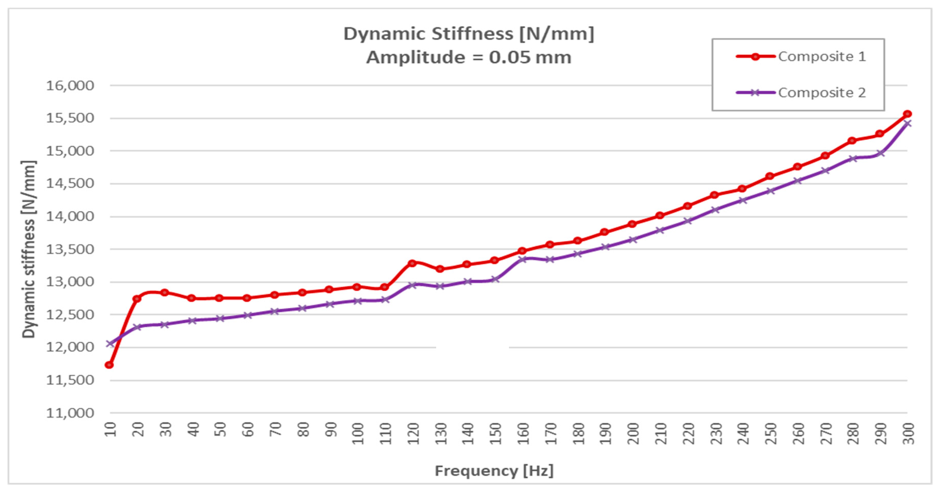
| 10 | 34,256 | 0.233 | 34,331 | 0.147 | 11,729 | 2.262 | 12,055 | 1.506 |
| 20 | 34,342 | 0.279 | 34,361 | 0.219 | 12,741 | 6.288 | 12,307 | 1.751 |
| 30 | 34,360 | 0.261 | 34,427 | 0.24 | 12,830 | 1.998 | 12,352 | 1.427 |
| 40 | 34,418 | 0.341 | 34,452 | 0.302 | 12,747 | 1.586 | 12,411 | 1.390 |
| 50 | 34,410 | 0.299 | 34,498 | 0.29 | 12,752 | 1.407 | 12,438 | 1.330 |
| 60 | 34,479 | 0.347 | 34,538 | 0.314 | 12,755 | 1.339 | 12,490 | 1.333 |
| 70 | 34,534 | 0.323 | 34,539 | 0.264 | 12,803 | 1.376 | 12,554 | 1.283 |
| 80 | 34,507 | 0.375 | 34,531 | 0.259 | 12,837 | 1.354 | 12,596 | 1.281 |
| 90 | 34,478 | 0.345 | 34,478 | 0.250 | 12,878 | 1.283 | 12,664 | 1.266 |
| 100 | 34,304 | 0.299 | 34,359 | 0.256 | 12,923 | 1.331 | 12,713 | 1.206 |
| 110 | 33,994 | 1.514 | 33,487 | −0.259 | 12,921 | 1.186 | 12,733 | 1.147 |
| 120 | 45,439 | 22.307 | 42,165 | 10.251 | 13,285 | 1.43 | 12,952 | 1.436 |
| 130 | 37,044 | −4.653 | 43,656 | 0.734 | 13,201 | 1.316 | 12,934 | 1.355 |
| 140 | 39,726 | 2.035 | 36,846 | −0.614 | 13,264 | 1.28 | 13,003 | 1.243 |
| 150 | 32,932 | 1.943 | 40,027 | 4.756 | 13,329 | 1.434 | 13,043 | 1.419 |
| 160 | 33,405 | 3.927 | 28,793 | 1.287 | 13,470 | 1.266 | 13,341 | 1.326 |
| 170 | 21,054 | 3.656 | 34,289 | 2.537 | 13,568 | 1.287 | 13,342 | 1.259 |
| 180 | 35,282 | 2.523 | 36,215 | 0.644 | 13,624 | 1.231 | 13,430 | 1.208 |
| 190 | 30,014 | 14.632 | 41,479 | 4.399 | 13,755 | 1.262 | 13,532 | 1.202 |
| 200 | 40,526 | −3.663 | 39,515 | 0.130 | 13,886 | 1.189 | 13,649 | 1.183 |
| 210 | 33,485 | 8.844 | 38,101 | 5.692 | 14,011 | 1.206 | 13,790 | 1.218 |
| 220 | 39,846 | 2.455 | 28,101 | 2.563 | 14,161 | 1.064 | 13,929 | 1.154 |
| 230 | 35,077 | 15.351 | 35,187 | 0.74 | 14,326 | 1.068 | 14,104 | 0.962 |
| 240 | 37,237 | −9.829 | 37,398 | 1.556 | 14,426 | 1.056 | 14,251 | 0.991 |
| 250 | 39,115 | 7.724 | 36,520 | −0.963 | 14,608 | 0.969 | 14,392 | 0.948 |
| 260 | 32,850 | 1.209 | 37,678 | 1.795 | 14,756 | 0.997 | 14,548 | 0.969 |
| 270 | 34,637 | 7.642 | 16,703 | −2.709 | 14,926 | 0.918 | 14,699 | 0.946 |
| 280 | 35,156 | 6.177 | 25,741 | −1.459 | 15,154 | 0.89 | 14,885 | 0.804 |
| 290 | 37,167 | −2.529 | 38,107 | 0.448 | 15,258 | 1.454 | 14,964 | 0.950 |
| 300 | 39,057 | 1.467 | 36,282 | 1.778 | 15,559 | 0.577 | 15,426 | 1.102 |
| AMPLITUDE 0.1mm | ||||||||
|---|---|---|---|---|---|---|---|---|
| Freq. | STEEL A1 | STEEL A2 | COMPOSITE 1 | COMPOSITE 2 | ||||
| Stiffness | Ang. | Stiffness | Ang. | Stiffness | Ang. | Stiffness | Ang. | |
| Hz | [N/mm] | [°] | [N/mm] | [°] | [N/mm] | [°] | [N/m} | [°] |
| 10 | 33,410 | 0.876 | 33,988 | 0.469 | 11,382 | 2.982 | 11,785 | 2.115 |
| 20 | 33,538 | 1.116 | 33,919 | 0.939 | 12,560 | 2.688 | 12,034 | 2.193 |
| 30 | 33,575 | 1.145 | 34,010 | 0.862 | 12,522 | 2.262 | 12,083 | 1.89 |
| 40 | 33,499 | 1.19 | 33,928 | 1.077 | 12,458 | 1.883 | 12,134 | 1.81 |
| 50 | 33,656 | 1.269 | 34,030 | 1.154 | 12,452 | 1.769 | 12,183 | 1.76 |
| 60 | 33,696 | 1.328 | 34,033 | 0.940 | 12,477 | 1.693 | 12,236 | 1.73 |
| 70 | 33,717 | 1.351 | 34,031 | 0.978 | 12,510 | 1.688 | 12,284 | 1.69 |
| 80 | 33,698 | 1.297 | 34,160 | 1.135 | 12,549 | 1.639 | 12,327 | 1.66 |
| 90 | 33,634 | 1.531 | 34,032 | 1.054 | 12,593 | 1.635 | 12,379 | 1.64 |
| 100 | 33,616 | 1.803 | 34,013 | 0.534 | 12,628 | 1.613 | 12,427 | 1.60 |
| 110 | 16,623 | 3.126 | 32,798 | 2.281 | 12,629 | 1.574 | 12,459 | 1.59 |
© 2019 by the authors. Licensee MDPI, Basel, Switzerland. This article is an open access article distributed under the terms and conditions of the Creative Commons Attribution (CC BY) license (http://creativecommons.org/licenses/by/4.0/).
Share and Cite
Tobalina-Baldeon, D.; Sanz-Adan, F.; Martinez-Calvo, M.A.; Santamaría-Pena, J. Dynamic Tensile Stress-Compressive Stress Behavior of Thermoplastic Matrix Composite Materials Reinforced with Continuous Fiber for Automotive Damping and Anti-Vibration Structural Elements. Materials 2020, 13, 5. https://doi.org/10.3390/ma13010005
Tobalina-Baldeon D, Sanz-Adan F, Martinez-Calvo MA, Santamaría-Pena J. Dynamic Tensile Stress-Compressive Stress Behavior of Thermoplastic Matrix Composite Materials Reinforced with Continuous Fiber for Automotive Damping and Anti-Vibration Structural Elements. Materials. 2020; 13(1):5. https://doi.org/10.3390/ma13010005
Chicago/Turabian StyleTobalina-Baldeon, D., F. Sanz-Adan, M.A. Martinez-Calvo, and J. Santamaría-Pena. 2020. "Dynamic Tensile Stress-Compressive Stress Behavior of Thermoplastic Matrix Composite Materials Reinforced with Continuous Fiber for Automotive Damping and Anti-Vibration Structural Elements" Materials 13, no. 1: 5. https://doi.org/10.3390/ma13010005
APA StyleTobalina-Baldeon, D., Sanz-Adan, F., Martinez-Calvo, M. A., & Santamaría-Pena, J. (2020). Dynamic Tensile Stress-Compressive Stress Behavior of Thermoplastic Matrix Composite Materials Reinforced with Continuous Fiber for Automotive Damping and Anti-Vibration Structural Elements. Materials, 13(1), 5. https://doi.org/10.3390/ma13010005