Friction Stir Spot Welding of Aluminum and Copper: A Review

 ,
,  ,
, 
Abstract
1. Introduction
2. Tool Features
3. Macroscopic Characteristics of Welded Joints
4. Microstructure
4.1. Material Flow
4.2. Interfacial Microstructure Features
4.3. Microstructure of the Al Side
4.4. Microstructure of Cu Side
5. Defects in Welds
6. Thermal History During Welding
7. Mechanical Properties
7.1. Hardness Distribution
7.2. Tensile Properties
8. Summary and Outlook
Author Contributions
Funding
Conflicts of Interest
References
- Zhang, W.; Shen, Y.F.; Yan, Y.F.; Guo, R.; Guan, W.; Guo, G.L. Microstructure characterization and mechanical behavior of dissimilar friction stir welded Al/Cu couple with different joint configurations. Int. J. Adv. Manuf. Tech. 2018, 94, 1021–1030. [Google Scholar] [CrossRef]
- Zhang, C.C.; Shirzadi, A.A. Measurement of residual stresses in dissimilar friction stir-welded aluminium and copper plates using the contour method. Sci. Technol. Weld. J. 2018, 23, 394–399. [Google Scholar] [CrossRef]
- Miller, W.S.; Zhuang, L.; Bottema, J.; Wittebrood, A.J.; De Smet, P.; Haszler, A.; Vieregge, A. Recent development in aluminium alloys for the automotive industry. Mater. Sci. Eng. A 2000, 280, 37–49. [Google Scholar] [CrossRef]
- Sahlot, P.; Singh, A.K.; Badheka, V.J.; Arora, A. Friction Stir Welding of Copper: Numerical Modeling and Validation. Trans. Indian Inst. Met. 2019, 72, 1339–1347. [Google Scholar] [CrossRef]
- Heidarzadeh, A.; Laleh, H.M.; Gerami, H.; Hosseinpour, P.; Shabestari, M.J.; Bahari, R. The origin of different microstructural and strengthening mechanisms of copper and brass in their dissimilar friction stir welded joint. Mater. Sci. Eng. A-Struct. 2018, 735, 336–342. [Google Scholar] [CrossRef]
- Ouyang, J.H.; Yarrapareddy, E.; Kovacevic, R. Microstructural evolution in the friction stir welded 6061 aluminum alloy (T6-temper condition) to copper. J. Mater. Process. Tech. 2006, 172, 110–122. [Google Scholar] [CrossRef]
- Lee, W.B.; Jung, S.B. Void free friction stir weld zone of the dissimilar 6061 aluminum and copper joint by shifting the tool insertion location. Mater. Res. Innov. 2004, 8, 93–96. [Google Scholar] [CrossRef]
- Lakshminarayanan, A.K.; Suresh, M.; Varshan, M.S. Thermal Performance Evaluation of Friction Stir Welded and Bolted Cold Plates with Al/Cu Interface. JoMus 2015, 67, 1032–1044. [Google Scholar] [CrossRef]
- Bisadi, H.; Tavakoli, A.; Sangsaraki, M.T.; Sangsaraki, K.T. The influences of rotational and welding speeds on microstructures and mechanical properties of friction stir welded Al5083 and commercially pure copper sheets lap joints. Mater. Des. 2013, 43, 80–88. [Google Scholar] [CrossRef]
- Li, G.H.; Zhou, L.; Zhou, W.L.; Song, X.G.; Huang, Y.X. Influence of dwell time on microstructure evolution and mechanical properties of dissimilar friction stir spot welded aluminum-copper metals. J. Mater. Res. Technol. 2019, 8, 2613–2624. [Google Scholar] [CrossRef]
- Zhou, L.; Li, G.H.; Zhang, R.X.; Zhou, W.L.; He, W.X.; Huang, Y.X.; Song, X.G. Microstructure evolution and mechanical properties of friction stir spot welded dissimilar aluminum-copper joint. J. Alloy Compd. 2019, 775, 372–382. [Google Scholar] [CrossRef]
- Acarer, M. Electrical, Corrosion, and Mechanical Properties of Aluminum-Copper Joints Produced by Explosive Welding. J. Mater. Eng. Perform. 2012, 21, 2375–2379. [Google Scholar] [CrossRef]
- Thomas, W.M.; Nicholas, E.D.; Needham, J.C.; Murch, M.G.; Temple-Smith, P.; Dawes, C.J. Friction Welding. U.S. Patent No. 5,460,317, 24 October 1995. [Google Scholar]
- Mishra, R.S.; Ma, Z. Friction stir welding and processing. Mater. Sci. Eng. R Rep. 2005, 50, 1–78. [Google Scholar] [CrossRef]
- Mahoney, M.W.; Mishra, R.S. Friction Stir Welding and Processing; ASM International: Cleveland, OH, USA, 2007. [Google Scholar]
- Thomas, W.; Norris, I.; Staines, D.; Watts, E. Friction Stir Welding-Process Developments and Variant Techniques; Society of Manufacturing Engineers: Dearborn, MI, USA, 2000. [Google Scholar]
- Zhang, C.Q.; Robson, J.D.; Ciuca, O.; Prangnell, P.B. Microstructural characterization and mechanical properties of high power ultrasonic spot welded aluminum alloy AA6111–TiAl6V4 dissimilar joints. Mater. Charact. 2014, 97, 83–91. [Google Scholar] [CrossRef]
- Zhang, C.Q.; Robson, J.D.; Prangnell, P.B. Dissimilar ultrasonic spot welding of aerospace aluminum alloy AA2139 to titanium alloy TiAl6V4. J. Mater. Process. Tech. 2016, 231, 382–388. [Google Scholar] [CrossRef]
- Zhang, C.Q.; Liu, W. Abnormal effect of temperature on intermetallic compound layer growth at aluminum-titanium interface: The role of grain boundary diffusion. Mater. Lett. 2019, 254, 1–4. [Google Scholar] [CrossRef]
- Zhang, C.; Robson, J.D.; Haigh, S.J.; Prangnell, P.B. Interfacial Segregation of Alloying Elements During Dissimilar Ultrasonic Welding of AA6111 Aluminum and Ti6Al4V Titanium. Metall. Mater. Trans. A 2019, 50, 5143–5152. [Google Scholar] [CrossRef]
- Zhang, C.Q.; Liu, W. Non-parabolic Al3Ti intermetallic layer growth on aluminum-titanium interface at low annealing temperatures. Mater. Lett. 2019, 256, 126624. [Google Scholar] [CrossRef]
- Eslami, N.; Harms, A.; Deringer, J.; Fricke, A.; Böhm, S. Dissimilar friction stir butt welding of aluminum and copper with cross-section adjustment for current-carrying components. Metals 2018, 8. [Google Scholar] [CrossRef]
- Chitturi, V.; Pedapati, S.R.; Awang, M. Effect of tilt angle and pin depth on dissimilar friction stir lap welded joints of aluminum and steel alloys. Materials 2019, 12. [Google Scholar] [CrossRef]
- Singh, B.; Mohanty, A. Analysis of thermal and mechanical properties of annealed surface modified nanodiamond/epoxy nanocomposites. Mater. Res. Express 2019, 6. [Google Scholar] [CrossRef]
- Wang, P.; Chen, D.; Ran, Y.; Yan, Y.; Peng, H.; Jiang, X. Fracture characteristics and analysis in dissimilar Cu-Al alloy joints formed via electromagnetic pulse welding. Materials 2019, 12. [Google Scholar] [CrossRef] [PubMed]
- Bellmann, J.; Lueg-Althoff, J.; Schulze, S.; Hahn, M.; Gies, S.; Beyer, E.; Tekkaya, A.E. Thermal Effects in Dissimilar Magnetic Pulse Welding. Metals 2019, 9, 348. [Google Scholar] [CrossRef]
- Kim, J.; Kim, J.; Kim, I.-j.; Kang, S.; Chun, K. An Analysis of Mechanical Properties for Ultrasonically Welded Multiple C1220-Al1050 Layers. Appl. Sci. 2019, 9, 4188. [Google Scholar] [CrossRef]
- Iwamoto, C.; Yamauchi, K.; Motomura, K.; Hashimoto, Y.; Hamada, K. Microstructure of Joint between Stranded Wire and Substrate Welded by Ultrasonic Welding. Appl. Sci. 2019, 9, 534. [Google Scholar] [CrossRef]
- Yang, J.; Zhang, J.; Qiao, J. Molecular Dynamics Simulations of Atomic Diffusion during the Al–Cu Ultrasonic Welding Process. Materials 2019, 12, 2306. [Google Scholar] [CrossRef] [PubMed]
- Peng, H.; Jiang, X.; Bai, X.; Li, D.; Chen, D. Microstructure and mechanical properties of ultrasonic spot welded Mg/Al alloy dissimilar joints. Metals 2018, 8. [Google Scholar] [CrossRef]
- Li, H.; Cao, B. Microstructure and Mechanical Properties of Resistance Heat-Assisted High-Power Ultrasonic Dissimilar Welded Cu/Al Joint. Metals 2019, 9, 873. [Google Scholar] [CrossRef]
- Macwan, A.; Chen, D.L. Microstructure and mechanical properties of ultrasonic spot welded copper-to-magnesium alloy joints. Mater. Des. 2015, 84, 261–269. [Google Scholar] [CrossRef]
- Iwashita, T. Method and apparatus for joining. US Patent 6601751 B2, 5 August 2003. [Google Scholar]
- Sakano, R.; Murakami, K.; Yamashita, K.; Hyoe, T.; Fujimoto, M.; Inuzuka, M.; Nagao, H.; Kashiki, H. Friction Stir Welding. In Proceedings of the Third International Symposium, Kobe, Japan, 27–28 September 2001. [Google Scholar]
- Mubiayi, M.P.; Akinlabi, E.T. Evolving properties of friction stir spot welds between AA1060 and commercially pure copper C11000. Trans. Nonferr. Metal. Soc. 2016, 26, 1852–1862. [Google Scholar] [CrossRef]
- Garg, A.; Bhattacharya, A. Strength and failure analysis of similar and dissimilar friction stir spot welds: Influence of different tools and pin geometries. Mater. Des. 2017, 127, 272–286. [Google Scholar] [CrossRef]
- Heideman, R.; Johnson, C.; Kou, S. Metallurgical analysis of Al/Cu friction stir spot welding. Sci. Technol. Weld. Join. 2010, 15, 597–604. [Google Scholar] [CrossRef]
- Ozdemir, U.; Sayer, S.; Yeni, C. Effect of Pin Penetration Depth on the Mechanical Properties of Friction Stir Spot Welded Aluminum and Copper. Mater Test 2012, 54, 233–239. [Google Scholar] [CrossRef]
- Macias, E.J.; Roca, A.S.; Fals, H.C.; Muro, J.C.S.; Fernandez, J.B. Characterisation of friction stir spot welding process based on envelope analysis of vibro-acoustical signals. Sci. Technol. Weld. Join. 2015, 20, 172–180. [Google Scholar] [CrossRef]
- Siddharth, S.; Senthilkumar, T. Optimization of friction stir spot welding process parameters of dissimilar Al 5083 and C 10100 joints using response surface methodology. Russ. J. Non-Ferr. Met. 2016, 57, 456–466. [Google Scholar] [CrossRef]
- Mubiayi, M.P.; Akinlabi, E.T.; Makhatha, M.E. Effect of Process Parameters on Tensile Strength and Morphology of Friction Stir Spot Welds of Aluminium and Copper. In Proceedings of the 2017 8th International Conference on Mechanical and Intelligent Manufacturing Technologies ICMIMT), Cape Town, South Africa, 3–6 February 2017; pp. 48–53. [Google Scholar]
- Zhou, L.; Zhang, R.X.; Li, G.H.; Zhou, W.L.; Huang, Y.X.; Song, X.G. Effect of pin profile on microstructure and mechanical properties of friction stir spot welded Al-Cu dissimilar metals. J. Manuf. Process. 2018, 36, 1–9. [Google Scholar] [CrossRef]
- Garg, A.; Bhattacharya, A. Similar and dissimilar joining of AA6061-T6 and copper by single and multi-spot friction stirring. J. Mater. Process. Technol. 2017, 250, 330–344. [Google Scholar] [CrossRef]
- Mubiayi, M.P.; Akinlabi, E.T. Characterization of the intermetallic compounds in aluminium and copper friction stir spot welds. Mater. Today-Proc. 2017, 4, 533–540. [Google Scholar] [CrossRef]
- Boucherit, A.; Avettand-Fenoel, M.N.; Taillard, R. Effect of a Zn interlayer on dissimilar FSSW of Al and Cu. Mater. Des. 2017, 124, 87–99. [Google Scholar] [CrossRef]
- Mubiayi, M.P.; Akinlabi, E.T.; Makhatha, M.E. Microstructure and Electrical Resistivity Properties of Copper and Aluminium Friction Stir Spot Welds. In Proceedings of the 2017 8th International Conference on Mechanical and Intelligent Manufacturing Technologies (ICMIMT), Cape Town, South Africa, 3–6 February 2017; pp. 42–47. [Google Scholar]
- Mubiayi, M.P.; Akinlabi, E.T.; Makhatha, M.E. Microstructure Evolution and Statistical Analysis of Al/Cu Friction-Stir Spot Welds. Mater. Tehnol. 2017, 51, 861–869. [Google Scholar] [CrossRef]
- Siddharth, S.; Senthilkumar, T. Evaluation of Friction Stir Spot Welded Al 5083 Aluminium Alloy and C10100 Copper Dissimilar Joints. Acta Microsc. 2017, 26, 1–10. [Google Scholar]
- Sanusi, K.O.; Akinlabi, E.T. Material Characterization of Dissimilar Friction Stir Spot Welded Aluminium and Copper Alloy. In Proceedings of the International Conference on Materials, Alloys and Experimental Mechanics (ICMAEM -2017), Narsimha Reddy Engineering College, India, 3–4 July 2017; Volume 225. [Google Scholar] [CrossRef]
- Siddharth, S.; Senthilkumar, T. Study of tool penetration behavior in dissimilar A15083/C10100 friction stir spot welds. Plast. Impact. Mech. 2017, 173, 1439–1446. [Google Scholar] [CrossRef]
- Siddharth, S.; Senthilkumar, T. Increasing the Fatigue Life of Dissimilar Friction Stir Spot Welded Al/Cu Joints by Optimization of Technological Parameters. J. Appl. Mech. Tech. Phys. 2018, 59, 326–331. [Google Scholar] [CrossRef]
- Siddharth, S.; Senthilkumar, T. Development of friction stir spot welding windows for dissimilar Al5086/C10100 spot joints. Mater. Today-Proc. 2018, 5, 6550–6559. [Google Scholar] [CrossRef]
- Siddharth, S.; Senthilkumar, T. Optimizing Process Parameters for Increasing Corrosion Resistance of Friction Stir Spot Welded Dissimilar Al-5086/C10100 Joints. Trans. Indian Inst. Met. 2018, 71, 1011–1024. [Google Scholar] [CrossRef]
- Siddharth, S.; Senthilkumar, T.; Chandrasekar, M. Development of processing windows for friction stir spot welding of aluminium Al5052/copper C27200 dissimilar materials. Trans. Nonferr. Metal. Soc. 2017, 27, 1273–1284. [Google Scholar] [CrossRef]
- Colmenero, A.N.; Orozco, M.S.; Macias, E.J.; Fernandez, J.B.; Muro, J.C.S.D.; Fals, H.C.; Roca, A.S. Optimization of friction stir spot welding process parameters for Al-Cu dissimilar joints using the energy of the vibration signals. Int. J. Adv. Manuf. Tech. 2019, 100, 2795–2802. [Google Scholar] [CrossRef]
- Regensburg, A.; Petzoldt, F.; Benss, T.; Bergmann, J.P. Liquid interlayer formation during friction stir spot welding of aluminum/copper. Weld. World 2019, 63, 117–125. [Google Scholar] [CrossRef]
- Cardillo, M.E.B.; Shen, J.J.; de Alcantara, N.G.; Afonso, C.R.M.; dos Santos, J.F. Effect of friction spot welding parameters on the joint formation and mechanical properties of Al to Cu. Weld. World 2019, 63, 33–41. [Google Scholar] [CrossRef]
- Wang, D.A.; Lee, S.C. Microstructures and failure mechanisms of friction stir spot welds of aluminum 6061-T6 sheets. J. Mater. Process. Tech. 2007, 186, 291–297. [Google Scholar] [CrossRef]
- Ma, Z.W.; Jin, Y.Y.; Ji, S.D.; Meng, X.C.; Ma, L.; Li, Q.H. A general strategy for the reliable joining of Al/Ti dissimilar alloys via ultrasonic assisted friction stir welding. J. Mater. Sci. Technol. 2019, 35, 94–99. [Google Scholar] [CrossRef]
- Dharmendra, C.; Rao, K.P.; Wilden, J.; Reich, S. Study on laser welding-brazing of zinc coated steel to aluminum alloy with a zinc based filler. Mater. Sci. Eng. A-Struct. 2011, 528, 1497–1503. [Google Scholar] [CrossRef]
- Chen, J.B.; Yuan, X.J.; Hu, Z.; Sun, C.Z.; Zhang, Y.X.; Zhang, Y.X. Microstructure and mechanical properties of resistance-spot-welded joints for A5052 aluminum alloy and DP 600 steel. Mater Charact. 2016, 120, 45–52. [Google Scholar] [CrossRef]
- Ye, Z.; Huang, J.H.; Gao, W.; Zhang, Y.F.; Cheng, Z.; Chen, S.H.; Yang, J. Microstructure and mechanical properties of 5052 aluminum alloy/mild steel butt joint achieved by MIG-TIG double-sided arc welding-brazing. Mater. Des. 2017, 123, 69–79. [Google Scholar] [CrossRef]
- Sun, D.Q.; Zhang, Y.Y.; Liu, Y.J.; Gu, X.Y.; Li, H.M. Microstructures and mechanical properties of resistance spot welded joints of 16Mn steel and 6063-T6 aluminum alloy with different electrodes. Mater. Des. 2016, 109, 596–608. [Google Scholar] [CrossRef]
- Horie, S.; Shinozaki, K.; Yamamoto, M.; North, T.H. Experimental investigation of material flow during friction stir spot welding. Sci. Technol. Weld. Join. 2010, 15, 666–670. [Google Scholar] [CrossRef]
- Lin, Y.C.; Liu, J.J.; Chen, J.N. Material Flow Tracking for Various Tool Geometries During the Friction Stir Spot Welding Process. J. Mater. Eng. Perform. 2013, 22, 3674–3683. [Google Scholar] [CrossRef]
- Yang, Q.; Mironov, S.; Sato, Y.S.; Okamoto, K. Material flow during friction stir spot welding. Mat. Sci. Eng. A-Struct. 2010, 527, 4389–4398. [Google Scholar] [CrossRef]
- Avettand-Fenoel, M.N.; Taillard, R.; Laye, J.; Odievre, T. Experimental Investigation of Three-Dimensional (3-D) Material Flow Pattern in Thick Dissimilar 2050 Friction-Stir Welds. Metall. Mater. Trans. A 2014, 45, 563–578. [Google Scholar] [CrossRef]
- Shi, H.; Chen, K.; Liang, Z.Y.; Dong, F.B.; Yu, T.W.; Dong, X.P.; Zhang, L.T.; Shan, A.D. Intermetallic Compounds in the Banded Structure and Their Effect on Mechanical Properties of Al/Mg Dissimilar Friction Stir Welding Joints. J. Mater. Sci. Technol. 2017, 33, 359–366. [Google Scholar] [CrossRef]
- Xue, P.; Ni, D.R.; Wang, D.; Xiao, B.L.; Ma, Z.Y. Effect of friction stir welding parameters on the microstructure and mechanical properties of the dissimilar Al-Cu joints. Mat. Sci. Eng. a-Struct. 2011, 528, 4683–4689. [Google Scholar] [CrossRef]
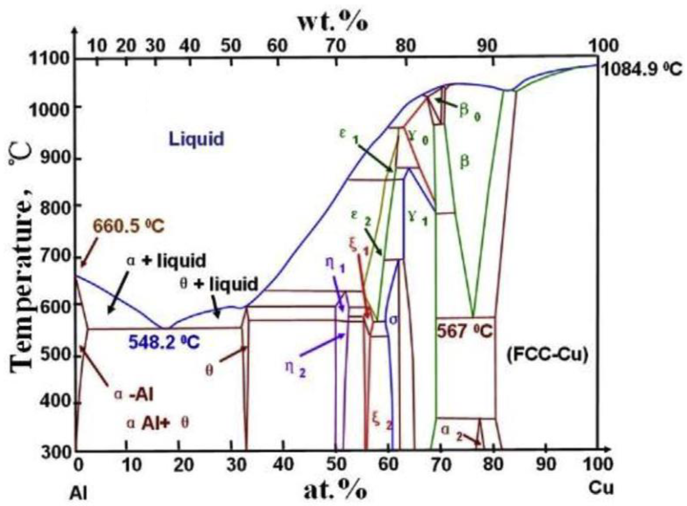
- Massalski, T.B. The Al−Cu (Aluminum-Copper) system. Bull. Alloy Phase Diagr. 1980, 1, 27–33. [Google Scholar] [CrossRef]
- Saeid, T.; Abdollah-Zadeh, A.; Sazgari, B. Weldability and mechanical properties of dissimilar aluminum–copper lap joints made by friction stir welding. J. Alloy Compd. 2010, 490, 652–655. [Google Scholar] [CrossRef]
- Elrefaey, A.; Takahashi, M.; Ikeuchi, K. Preliminary investigation of friction stir welding aluminium/copper lap joints. Weld. World 2005, 49, 93–101. [Google Scholar] [CrossRef]
- Lin, P.-C.; Lin, S.-H.; Pan, J. Modeling of Plastic Deformation and Failure Near Spot Welds in Lap-Shear Specimens; SAE Technical Paper: Detroit, Michigan, 2004. [Google Scholar]
- Sarkar, R.; Pal, T.K.; Shome, M. Material flow and intermixing during friction stir spot welding of steel. J. Mater. Process. Tech. 2016, 227, 96–109. [Google Scholar] [CrossRef]
- De Leon, M.; Shin, H.S. Material flow behaviours during friction stir spot welding of lightweight alloys using pin and pinless tools. Sci. Technol. Weld. Join. 2016, 21, 140–146. [Google Scholar] [CrossRef]
- Shen, J.J.; Suhuddin, U.F.H.; Cardillo, M.E.B.; dos Santos, J.F. Eutectic structures in friction spot welding joint of aluminum alloy to copper. Appl. Phys. Lett. 2014, 104. [Google Scholar] [CrossRef]
- Fu, R.D.; Sun, R.C.; Zhang, F.C.; Liu, H.J. Improvement of Formation Quality for Friction Stir Welded Joints. Weld. J. 2012, 91, 169s–173s. [Google Scholar]
- Periyasamy, P.; Mohan, B.; Balasubramanian, V. Effect of Heat Input on Mechanical and Metallurgical Properties of Friction Stir Welded AA6061-10% SiCp MMCs. J. Mater. Eng. Perform. 2012, 21, 2417–2428. [Google Scholar] [CrossRef]
- Abdollah-Zadeh, A.; Saeid, T.; Sazgari, B. Microstructural and mechanical properties of friction stir welded aluminum/copper lap joints. J. Alloy Compd. 2008, 460, 535–538. [Google Scholar] [CrossRef]
- Patel, V.V.; Badheka, V.; Kumar, A. Effect of polygonal pin profiles on friction stir processed superplasticity of AA7075 alloy. J. Mater. Process. Tech. 2017, 240, 68–76. [Google Scholar] [CrossRef]
- Huang, M.L.; Yang, F. Solder Size Effect on Early Stage Interfacial Intermetallic Compound Evolution in Wetting Reaction of Sn3.0Ag0.5Cu/ENEPIG Joints. J. Mater. Sci. Technol. 2015, 31, 252–256. [Google Scholar] [CrossRef]
- Schmidt, H.B.; Hattel, J.H. Thermal modelling of friction stir welding. Scr. Mater. 2008, 58, 332–337. [Google Scholar] [CrossRef]
- Su, P.; Gerlich, A.; North, T.H.; Bendzsak, G.J. Material flow during friction stir spot welding. Sci. Technol. Weld. Join. 2006, 11, 61–71. [Google Scholar] [CrossRef]
- Sun, S.; Li, J.; Zhao, Y.; Zhao, H.; Xu, R.; Liu, R. Study on eutectic transformation in Al-Cu alloys under 5 GPa pressure condition. Phys. Test Chem. Anal. Part A 2008, 44, 465–466. [Google Scholar]
- Xu, B.; Tong, W.P.; Liu, C.Z.; Zhang, H.; Zuo, L.; He, J.C. Effect of High Magnetic Field on Growth Behavior of Compound Layers during Reactive Diffusion between Solid Cu and Liquid Al. J. Mater. Sci. Technol. 2011, 27, 856–860. [Google Scholar] [CrossRef]
- Rajani, H.R.Z.; Esmaeili, A.; Mohammadi, M.; Sharbati, M.; Givi, M.K.B. The role of Metal-Matrix Composite development During Friction Stir Welding of Aluminum to Brass in Weld Characteristics. J. Mater. Eng. Perform. 2012, 21, 2429–2437. [Google Scholar] [CrossRef]
- Kerrar, G.; Merah, N.; Shuaib, A.N.; Al-Badour, F.; Bazoune, A. Experimental and Numerical Investigations of Friction Stir Welding of Aluminum to Copper. Lect. Notes Mech. Eng. 2017, 129–138. [Google Scholar] [CrossRef]
- Barcellona, A.; Buffa, G.; Fratini, L. Process parameters analysis in friction stir welding of AA6082-T6 sheets. In Proceedings of ESAFORM, Trondheim, Norway, 28–30 April 2004; pp. 371–374. [Google Scholar]
- Celik, S.; Cakir, R. Effect of Friction Stir Welding Parameters on the Mechanical and Microstructure Properties of the Al-Cu Butt Joint. Metals Basel 2016, 6, 133. [Google Scholar] [CrossRef]
- Shiraly, M.; Shamanian, M.; Toroghinejad, M.R.; Jazani, M.A. Effect of Tool Rotation Rate on Microstructure and Mechanical Behavior of Friction Stir Spot-Welded Al/Cu Composite. J. Mater. Eng. Perform. 2014, 23, 413–420. [Google Scholar] [CrossRef]
- Xiao, Y.; Ji, H.J.; Li, M.Y.; Kim, J. Ultrasound-assisted brazing of Cu/Al dissimilar metals using a Zn-3Al filler metal. Mater. Des. 2013, 52, 740–747. [Google Scholar] [CrossRef]
- Threadgill, P.; Leonard, A.; Shercliff, H.; Withers, P. Friction stir welding of aluminium alloys. Int. Mater. Rev. 2009, 54, 49–93. [Google Scholar] [CrossRef]
- Akinlabi, E.T. Effect of Shoulder Size on Weld Properties of Dissimilar Metal Friction Stir Welds. J. Mater. Eng. Perform. 2012, 21, 1514–1519. [Google Scholar] [CrossRef]
- Tan, C.W.; Jiang, Z.G.; Li, L.Q.; Chen, Y.B.; Chen, X.Y. Microstructural evolution and mechanical properties of dissimilar Al-Cu joints produced by friction stir welding. Mater. Des. 2013, 51, 466–473. [Google Scholar] [CrossRef]
- Li, X.W.; Zhang, D.T.; Qiu, C.; Zhang, W. Microstructure and mechanical properties of dissimilar pure copper/1350 aluminum alloy butt joints by friction stir welding. Trans. Nonferr. Metal. Soc. 2012, 22, 1298–1306. [Google Scholar] [CrossRef]


| Technical Terms | Abbreviations |
|---|---|
| Aluminum | Al |
| Base material | BM |
| Conical pin and concave shoulder | CCS |
| Copper | Cu |
| Electron microprobe analysis | EMPA |
| Energy dispersive spectroscopy | EDS |
| Electromagnetic pulse welding | EMPW |
| Flat pin and flat shoulder | FPS |
| Friction stir spot welding | FSSW |
| Friction stir welding | FSW |
| Fully bonded region | FBR |
| Heat affected zone | HAZ |
| Hook height | HH |
| Hook interface back to the keyhole | IBK |
| Hook interface facing the keyhole | IFK |
| Intermetallic compound | IMC |
| Onion zone | OZ |
| Probability distribution function | |
| Stir zone | SZ |
| Thermo-mechanically affected zone | TMAZ |
| Shoulder | Pin | Joint Strength (Shear Force, kN) | Ref. | |||
|---|---|---|---|---|---|---|
| Diameter (mm) | Morphology | Diameter (mm) | Length (mm) | Morphology | ||
| 10 | Concave | 4 | 1.83/ 2.60 | Threaded | 1.7/ 2.0 | [37] |
| 20 | Flat | 5 | 2.8/ 4.0/ 5.0 | Threaded | 1.8/ 3.9/ 3.2 | [38] |
| 10 | Concave | 3 | 4.5 | Close to 4.8 | [39] | |
| 15 | Flat/ Concave | 5 | 4 | Flat/ Conical | 5.2/ 4.8 | [35,41,44,46,47] |
| 16 | Flat | 6 | 1.2 | Cylindrical | 2.6 | [40,48] |
| 16 | Flat | 6 | 1.5/ 2.5/ 6.0 | Tapered and threaded | 2.8/ 3.4/ 4.6 (with 0.5 mm Zinc layer) | [45] |
| 10 | Flat | Pinless tool | 1.7 (Shear force)/ 0.3 (Cross tensile force) | [43] | ||
| 10 | Flat | Pinless tool/ | 1.9 1.5/1.1 1.6/1.3 | [36] | ||
| 3.3/ 4.95 | 0.2/0.4 0.2/0.4 | Cylindrical/ Cylindrical | ||||
| 18 | Flat | 5 | 4.5 | Cylindrical | 4.5 | [49] |
| 16 | Flat | 6 | 1.5 | Cylindrical | 3.8 | [50,51,52,53] |
| 16 | Flat | 6 | 1 | Cylindrical | 3.8 | [54] |
| 14 | Concave | 4.6 | 2.85 | Cylindrical/ threaded pin/ threaded pin with flutes | 2.7/ 4.3/ 3.1 | [10,11,42] |
| 10 | Concave | 3 | 4.5 | Cylindrical | 4.8 | [55] |
| 12 | Flat | 8 | 0.3-0.4 | Cylindrical | Close to 3.4 | [56] |
| Refill-FSSW 14.5 mm (clamping ring) 9 mm (sleeve) | 6 | Threaded | 7.1 | [57] | ||
| Materials | Interface Position | IMC Types | IMC Thickness | Ref. |
|---|---|---|---|---|
| Pure Cu/ Pure Al | Cu-Al interface: | Al2Cu Al4Cu9 | Total: 3.25 µm; Al2Cu: 2.30 µm; Al4Cu9: 0.95 µm | [45] |
| Pure Cu/ AA6061 Al | Cu-Al interface: | Major elements in IMC layer are Al, Cu and notable amount of oxygen. | Varied from 6.56 to 147.70 µm | [43] |
| AA1060 Al/ C11000 Cu | Al-Cu Hook interface: | FPS/800 rpm: AlCu3, Al4Cu9, Al2Cu, Al3Cu2, Al2Cu3, AlCu; FPS/1200 rpm: AlCu3, Al4Cu9, Al2Cu, AlCu; CCS/800 rpm: AlCu3, Al4Cu9, Al2Cu, Al3Cu2; CCS/1200 rpm: AlCu3, Al4Cu9, Al2Cu, Al3Cu2 | Not mentioned | [35] |
| CW004 Cu/ AW1050 Al | Cu-Al interface: | 2200 rpm: melt layer (within Al2Cu dendrites); 2400 rpm: melt layer (within Al2Cu, AlCu and Al4Cu9) | 2200 rpm: melt layer >100 µm; 2400 rpm: melt layer >300 µm; The thickness of IMC inside the melt layer < 5µm | [56] |
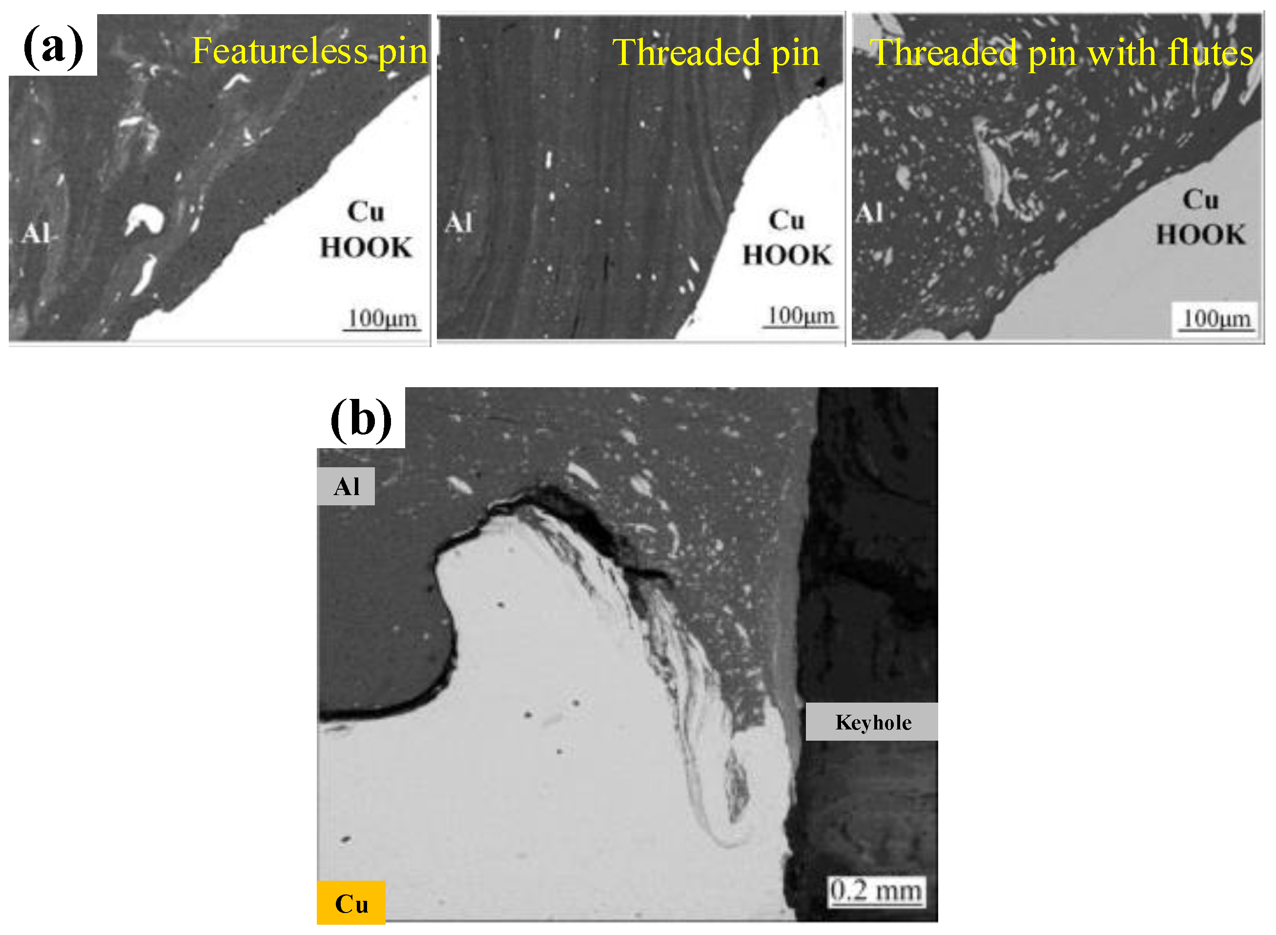
| 1060 Al/ T2 Cu | Al-Cu Hook interface: | Al2Cu AlCu Al4Cu9 | Featureless pin: IFK: 1.3 µm (Al2Cu- AlCu-Al4Cu9); IBK: 0.6 µm (Al2Cu); Threaded pin: IFK: 2.8 µm (Al2Cu- AlCu-Al4Cu9); IBK: 1.0 µm (Al2Cu- AlCu); Threaded pin with flutes: IFK: 1.9 µm (Al2Cu- AlCu-Al4Cu9); IBK: 1.4 µm (Al2Cu- AlCu-Al4Cu9) | [42] |
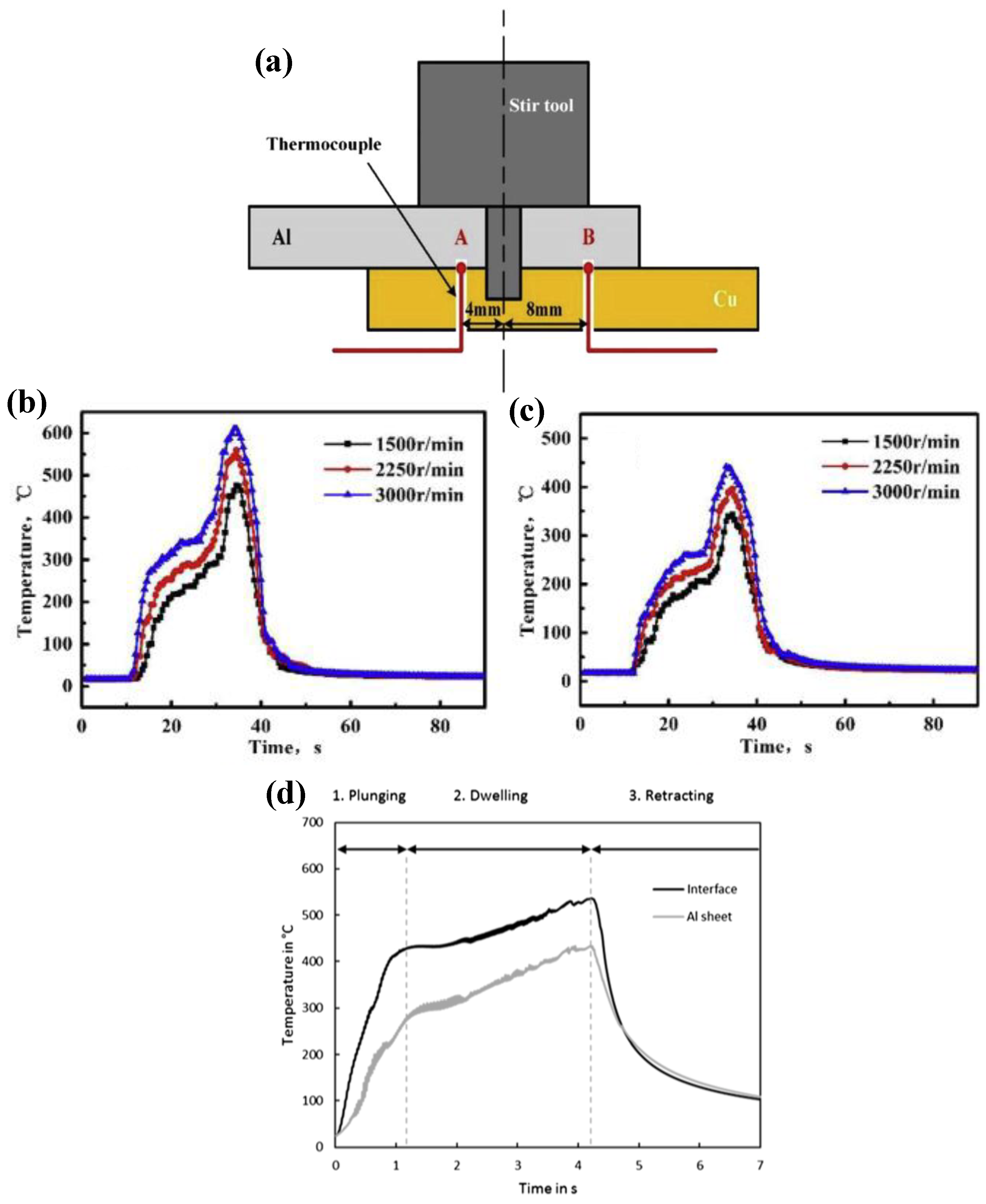
| 1060 Al/ T2 Cu | Al-Cu Hook interface: | Al2Cu AlCu Al4Cu9 | 1500 rpm: IFK: 2.0 µm (Al2Cu- AlCu-Al4Cu9); IBK: 0.2 µm (Al2Cu); 2250 rpm: IFK: 2.8 µm (Al2Cu- AlCu-Al4Cu9); IBK: 1.0 µm (Al2Cu- AlCu); 3000 rpm: IFK: 3.4 µm (Al2Cu- AlCu-Al4Cu9); IBK: 1.8 µm (Al2Cu- AlCu-Al4Cu9) | [11] |
| Rotational Speed (rpm) | Plunge Depth (mm) | Dwell Time (s) | Peak Temperature at the Al-Cu Interface (°C) |
|---|---|---|---|
| 1200 | 1.6 | 0 | 460 |
| 1200 | 1.8 | 2 | 481 |
| 1200 | 2 | 2 | 478 |
| 2000 | 2 | 2 | 504 |
| Materials | Max. Shear Load (N) | Tool Features | Welding Parameters: R/rpm (Rotational Speed), D/mm (Plunge Depth), T/s (Dwell Time) | Ref. |
|---|---|---|---|---|
| 6061-T6 Al (1.5 mm) and pure Cu (1.5 mm) | 2080 N | Concave shoulder (10.0 mm diameter) and threaded pin (2.6 mm length) | R = 2000 rpm D = 0.13 mm T = 3 s | [37] |
| AA1050 Al (3.0 mm) and pure Cu (3.0 mm) | 3950 N | Flat shoulder (20.0 mm diameter) and threaded pin (4.0 mm length) | R = 1600 rpm T = 10 s | [38] |
| AA1060 Al (3.0 mm) and pure Cu (3.0 mm) | 5225 N | Flat shoulder (15.0 mm diameter) and flat pin (4.0 mm length) | R = 800 rpm D = 1.0 mm T = 10 s | [35,41] |
| 5083 Al (1.5 mm) and C10100 Cu (1.5 mm) | 2600 N | Flat shoulder (16.0 mm diameter) and cylindrical pin (1.2 mm length) | R = 1250 rpm D = 0.7 mm T = 12.5 s | [40] |
| Pure Cu (5.0 mm) and pure Al (2.0 mm) | 4610 N | Flat shoulder (16.0 mm diameter) and tapered pin with thread (4.0 mm length) | R = 1400 rpm T = 8 s | [45] |
| Pure Cu (0.5 mm) and AA6061-T6 Al (0.5 mm) | 1728 N | Pinless tool with flat shoulder (10.0 mm diameter) | R = 2500 rpm D = 0.2 mm T = 4 s | [43] |
| 5083 Al (1.5 mm) and C10100 Cu (1.5 mm) | 1120 N | Flat shoulder (16.0 mm diameter) and cylindrical pin (1.2 mm length) | R = 1250 rpm D = 0.9 mm T = 12 s | [48] |
| 5083 Al (1.5 mm) and C10100 Cu (1.5 mm) | 3780 N | Flat shoulder (16.0 mm diameter) and cylindrical pin (1.5 mm length) | R = 1000 rpm D = 0.5 mm T = 18 s | [50] |
| 5052 Al (1.5 mm) and C27200 Cu (1.6 mm) | 3908 N | Flat shoulder (16.0 mm diameter) and cylindrical pin (1.0 mm length) | R = 1350 rpm D = 0.95 mm T = 13.5 s | [54] |
| 5086 Al (1.5 mm) and C10100 Cu (1.6 mm) | 2190 N | Flat shoulder (16.0 mm diameter) and cylindrical pin (1.5 mm length) | R = 1100 rpm D = 0.55 mm T = 11.5 s | [52] |
| 1060 Al (2.0 mm) and T2 Cu (2.0 mm) | 4304 N | Concave shoulder (14.0 mm diameter) and cylindrical pin with thread (2.85 mm length) | R = 2250 rpm D = 0.1 mm T = 5 s | [10,11,42] |
| AA5083 Al (2.0 mm) and Cu DHP (2.0 mm) | 7110 N (Refill-FSSW) | Threaded tool with clamping ring (14.5 mm diameter), sleeve (9.0 mm diameter) and pin (6.0 mm diameter) | R = 1200 rpm D = 2 mm (Sleeve plunge depth) T = 2 s | [57] |
| Pure Cu (3.0 mm) and AA1050-H24 (3.0 mm) | 4830 N | Concave shoulder (10.0 mm diameter) and cylindrical pin (4.5 mm length) | R = 1255 rpm D = 0.2 mm T = 4 s | [55] |
© 2019 by the authors. Licensee MDPI, Basel, Switzerland. This article is an open access article distributed under the terms and conditions of the Creative Commons Attribution (CC BY) license (http://creativecommons.org/licenses/by/4.0/).
Share and Cite
Li, M.; Zhang, C.; Wang, D.; Zhou, L.; Wellmann, D.; Tian, Y. Friction Stir Spot Welding of Aluminum and Copper: A Review. Materials 2020, 13, 156. https://doi.org/10.3390/ma13010156
Li M, Zhang C, Wang D, Zhou L, Wellmann D, Tian Y. Friction Stir Spot Welding of Aluminum and Copper: A Review. Materials. 2020; 13(1):156. https://doi.org/10.3390/ma13010156
Chicago/Turabian StyleLi, Mingshen, Chaoqun Zhang, Dayong Wang, Li Zhou, Daniel Wellmann, and Yingtao Tian. 2020. "Friction Stir Spot Welding of Aluminum and Copper: A Review" Materials 13, no. 1: 156. https://doi.org/10.3390/ma13010156
APA StyleLi, M., Zhang, C., Wang, D., Zhou, L., Wellmann, D., & Tian, Y. (2020). Friction Stir Spot Welding of Aluminum and Copper: A Review. Materials, 13(1), 156. https://doi.org/10.3390/ma13010156