1. Introduction
Reinforced concrete (RC) structures are currently designed to satisfy ultimate and serviceability limit states [
1]. Nevertheless, as stated by Model Code 2010 [
2], the design of structures is a process of developing a suitable solution in which not only must safety and functionality be guaranteed during service life, but also sustainability must be assured. Although green concrete structures are achieved via different approaches [
3], two possible strategies can be applied to better fulfill environmental requirements [
4]:
Material performance strategy, aimed at the reduction of clinker and thus of the volume of structures, by increasing the mechanical performance of concrete.
Material substitution strategy, which consists of substituting clinker with cementitious and/or pozzolanic mineral admixtures (e.g., fly ashes, silica fumes, etc.).
In several cases, these two strategies are contemporarily used, such as in the substitution of cement with supplementary cementitious materials (SCMs), which can be byproducts of the industrial process. For instance, coal fly ashes, deriving from the combustion of coal in power plants and which can be used to partially substitute Portland cement, can also enhance the strength and the durability of traditional concrete [
5].
From a practical point of view, the abovementioned strategies are not well integrated into the current limit state design approach. In other words, there is not a single procedure capable of assuring structural safety while also minimizing the environmental impact of concrete elements. In almost all cases, after designing the mechanical performance of RC structures, the environmental impact is assessed through broad-based green building rating schemes [
2]. As the most common rating systems grant a posteriori (i.e., after building the structure) sustainability certificate, the sustainability and the mechanical performances of different concretes cannot be compared [
6,
7,
8]. Hence, the European Union (EU) target to reduce the greenhouse gasses GHG emissions by 20% [
9] cannot be fulfilled by the cement and concrete industry if the current mechanical and environmental approaches used to design RC structures are not integrated.
In the opinion of the authors, to design more sustainable reinforced concrete structures, a new limit state has to be introduced and used in combination with the traditional limit states. In this way, a code-specific language addressing sustainability practices, which is one of the key objectives of the American Concrete Institute ACI Concrete Sustainability Forum [
10], can be developed. Thus, here, a simply supported beam is designed not only to satisfy the bearing capacity and deflection limits, but also to reduce, as much as possible, the environmental impact and fulfill the EU target [
9]. Specifically, an integrated ecological and mechanical procedure is herein proposed to select the best concrete with the optimal replacement rate of cement with fly ash.
2. The Sustainability of Materials
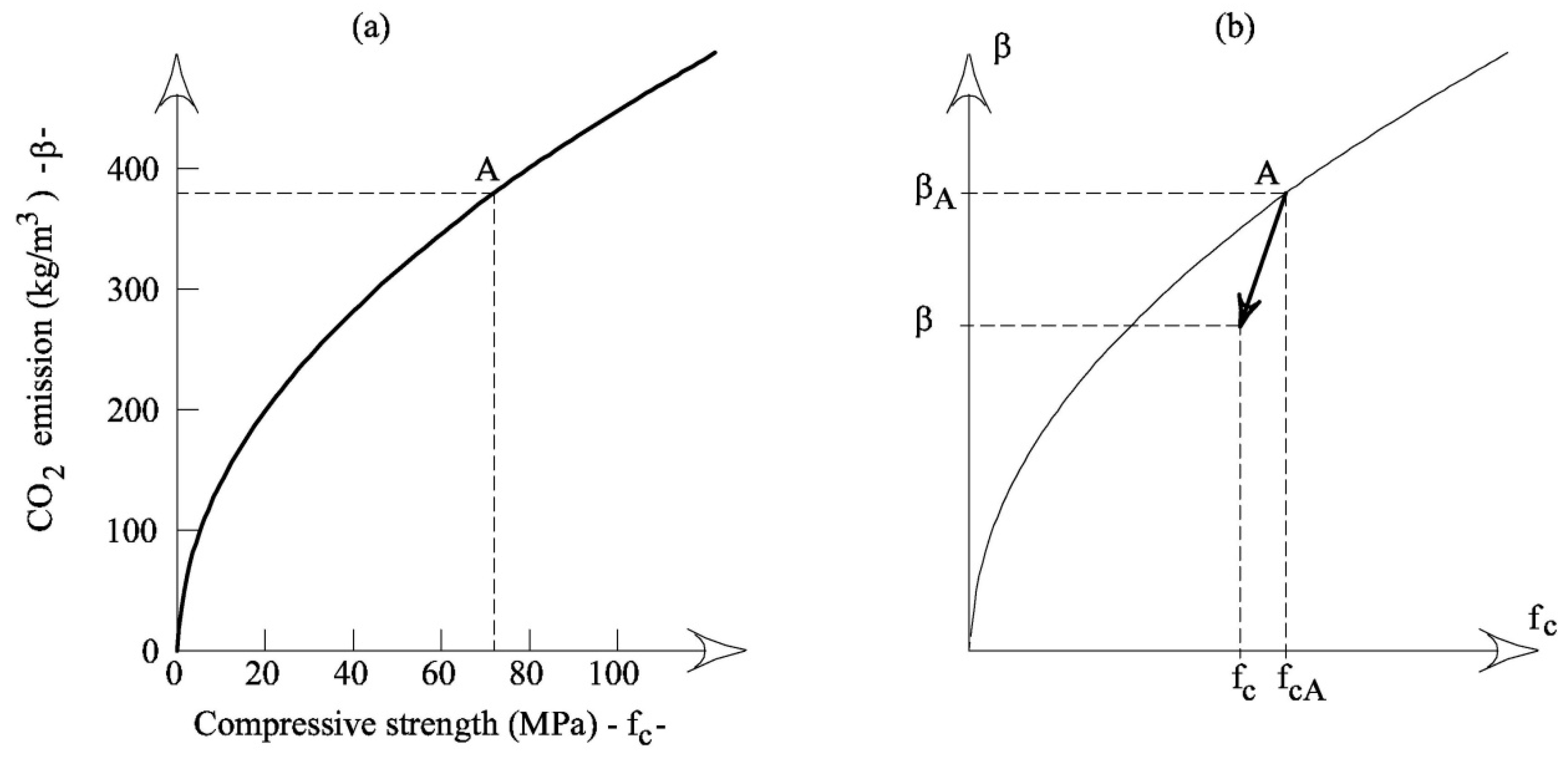
In the material performance strategy, the CO
2 emitted per cubic meter of concrete increases with the concrete strength. According to Habert’s and Roussel’s [
4] model (see
Figure 1a), a quadratic function can define this relationship:
where
β = mass of CO
2 emitted by the production of a cubic meter of concrete (whose binder is only cement);
fc = average compressive strength of concrete (whose binder is only cement); and
δ = coefficient of proportionality.
Conversely, the application of the substitution strategy, e.g., replacing part of the cement with fly ash, produces a decrement of the initial values of CO
2 emission,
βA, and concrete strength,
fcA, in a specific concrete system (
Figure 1b).
The new values of
fc and
β of concrete in which part of the cement is substituted by fly ash, depend on the initial values
βA and
fcA (of a concrete made by only cement) and on the rate of substitution
S. Thus, for given values of
βA,
fcA, and
S, by means of the following functions, both
fc and
β can be evaluated:
where
S = is the substitution rate of cement with fly ash that modifies
fcA and
βA into
fc and
β, respectively;
α = strength coefficient; and
γ = sustainability coefficient. Obviously, for a specific concrete system, the three coefficients
α,
δ, and
γ have to be evaluated through the regression analyses of the available experimental data.
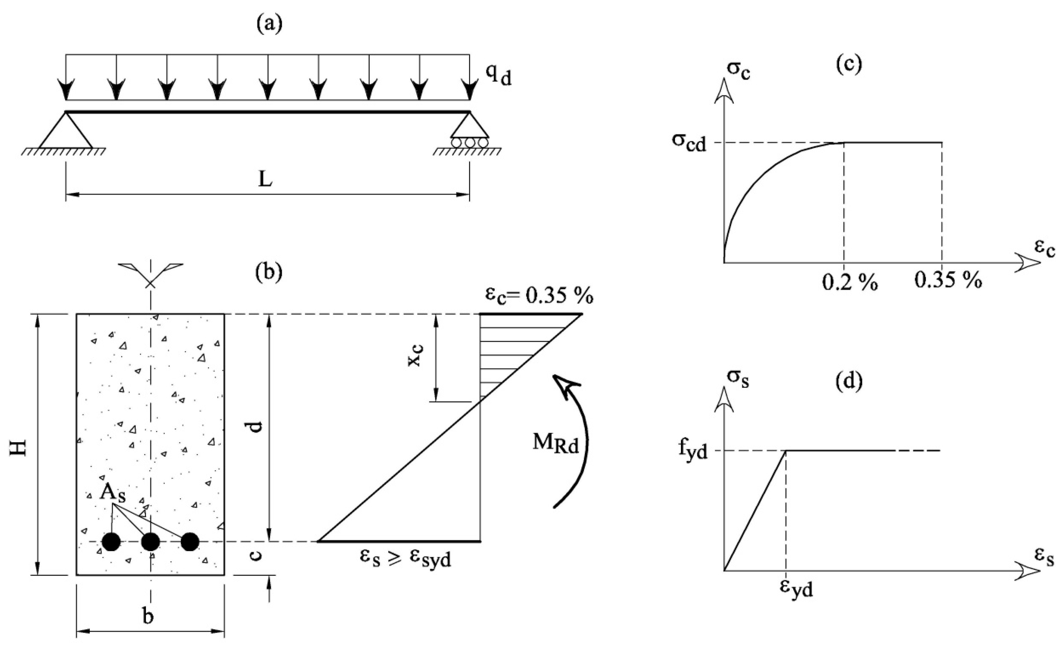
3. The Limit States of an RC Beam in Bending
According to Eurocode 2 (EC2) [
1] the ultimate limit states of RC beams in bending (
Figure 4a,b) depend on the constitutive relationships of materials. For normal-weight concrete of a class lower than 50 MPa, the parabola–rectangle relationship illustrated in
Figure 4c can be used. The bilinear elastic–perfectly plastic relationship is assumed for steel in tension (
Figure 4d). In the latter, after yielding (i.e.,
εs >
εyd =
fyd/
Es, where
Es = 200 GPa = elastic modulus of steel), the stress is constant and equal to the yielding strength, regardless of the strain.
The design strengths of both materials are computed in accordance with the partial safety factors given by Eurocode 2 [
1]:
where
fck = characteristic compressive cylinder strength of concrete at 28 days;
fyk = characteristic yield strength of reinforcement;
γc = 1.5 = partial safety factor of concrete; and
γs = 1.15 = partial safety factor of steel.
With the constitutive laws illustrated in
Figure 4c,d, an RC cross-section can be designed in order to satisfy the following condition:
where
MEd = design bending moment applied to the cross-section and produced by the external actions and
MRd = design bending moment capacity of the cross-section.
The value of
MRd can be analytically computed assuming the limit strain conditions illustrated in
Figure 4b. Specifically, the maximum strain of concrete is reached in the compressed edge of the beam, whereas the strain of steel in tension should be larger than or equal to that at yielding (i.e.,
εs ≥
εyd).
Under these assumptions, the equilibrium and compatibility equations provide [
12]:
where, according to the symbols reported in
Figure 4b, the following non-dimensional geometrical and mechanical properties are taken into consideration
If the value of ξ is fixed, the optimal values of ω and μRd can be calculated through Equation (7).
Generally, code rules fix the minimum and the maximum value of the reinforcement area [
1,
2] as follows:
where
k1 = 1.4 and
k2 = 3.5 are the values used in Italy.
To reduce the volume of the cross-section, it is better to design the area
As close to the upper bound of Equation (11), thus:
If Equation (12) is substituted into Equation (7a), the optimal value of
ξ can be obtained:
It must be noted that in the case of concrete C25 (which is the most used in Italy), the value of
ξ = 0.25 is obtained when
k2 = 3.5 and
γs = 1.15. As stated by EC2 [
1], the plastic analysis of beams, frames, and slabs can be performed without the explicit verification of the required ductility when
ξ ≤0.25 for concrete strength classes lower than C50.
Finally, by substituting Equation (9) into Equation (12) and Equation (10) and Equation (13) into Equation (7b), the following formulae can be obtained:
As the direct computation of deflection is not always necessary [
1], the span/depth ratio is herein limited for avoiding deflection problems in RC beams. In other words:
where
L= span length of the beam (
Figure 4a);
H = height of the beam (
Figure 4a); and
ψ = coefficient.
The depth of the concrete cover
c is related to durability requirements. Thus, it depends on the environmental conditions (i.e., the class of exposition), and it can be assumed as a fraction of the height H:
where
ρ = coefficient.
4. A New Design Procedure for RC Beams in Bending
When a concrete system is introduced (and, therefore,
δ,
α and
γ are known), it is possible to select a specific value of strength
fc (herein assumed as the average value of strength) and the corresponding coefficient
β. For the beam depicted in
Figure 4a, the length of the span
L, the density of concrete
De, and the applied load
qd are the input data. The values of the depth
H and concrete cover
c can be obtained from the coefficients
ψ and
ρ, regarding the serviceability (control of deflection) and the durability requirements, respectively.
Under these conditions, to obtain the geometry of the beam, only the width
b and the area of the reinforcement
As have to be calculated. Such values mainly depend on the maximum bending moment acting on the beam:
where 1.3 and 1.5 are the partial safety factors of the structural weight and service load.
If Equation (17) is substituted into Equation (14b), and assuming
d =
H −
c, then the width
b can be obtained:
The area of reinforcement in tension is then computed with Equation (14a), and the global impact of the beam
BI, in terms of CO
2 released into the atmosphere, is:
where
ϕ is the environmental impact of steel as obtained from
Table 2.
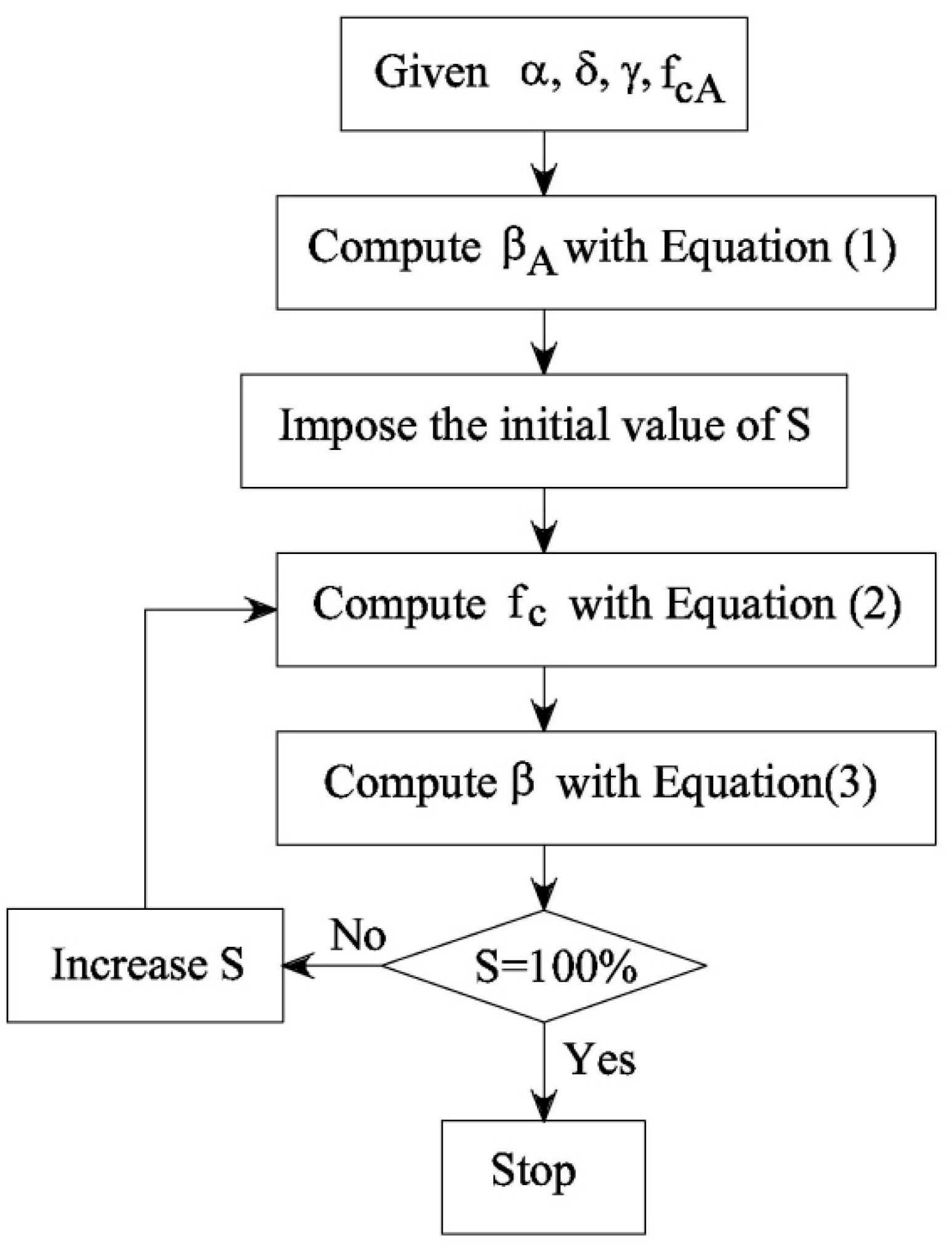
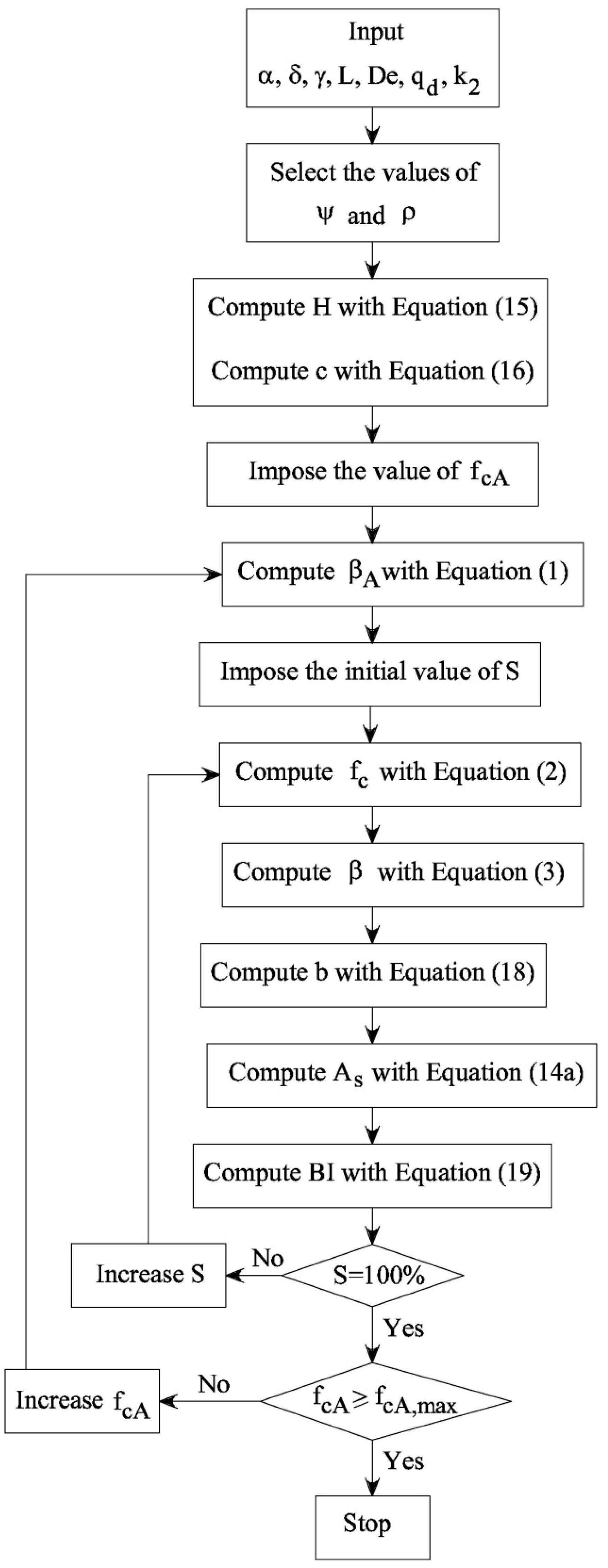
The procedure illustrated in
Figure 2 and used to calculate the
fc-
S and
β-
S functions can now be extended to calculate the relationships
b–
S,
As–
S, and
BI–
S of the RC beam illustrated in
Figure 4a. The flow chart of the new procedure is drawn in
Figure 5, whereas
Figure 6 shows the curves computed in the case of
fckA = 25 MPa (
fckA = the characteristic value of strength in the absence of cement substitution =
fcA − 8 MPa [
1,
2]) and:
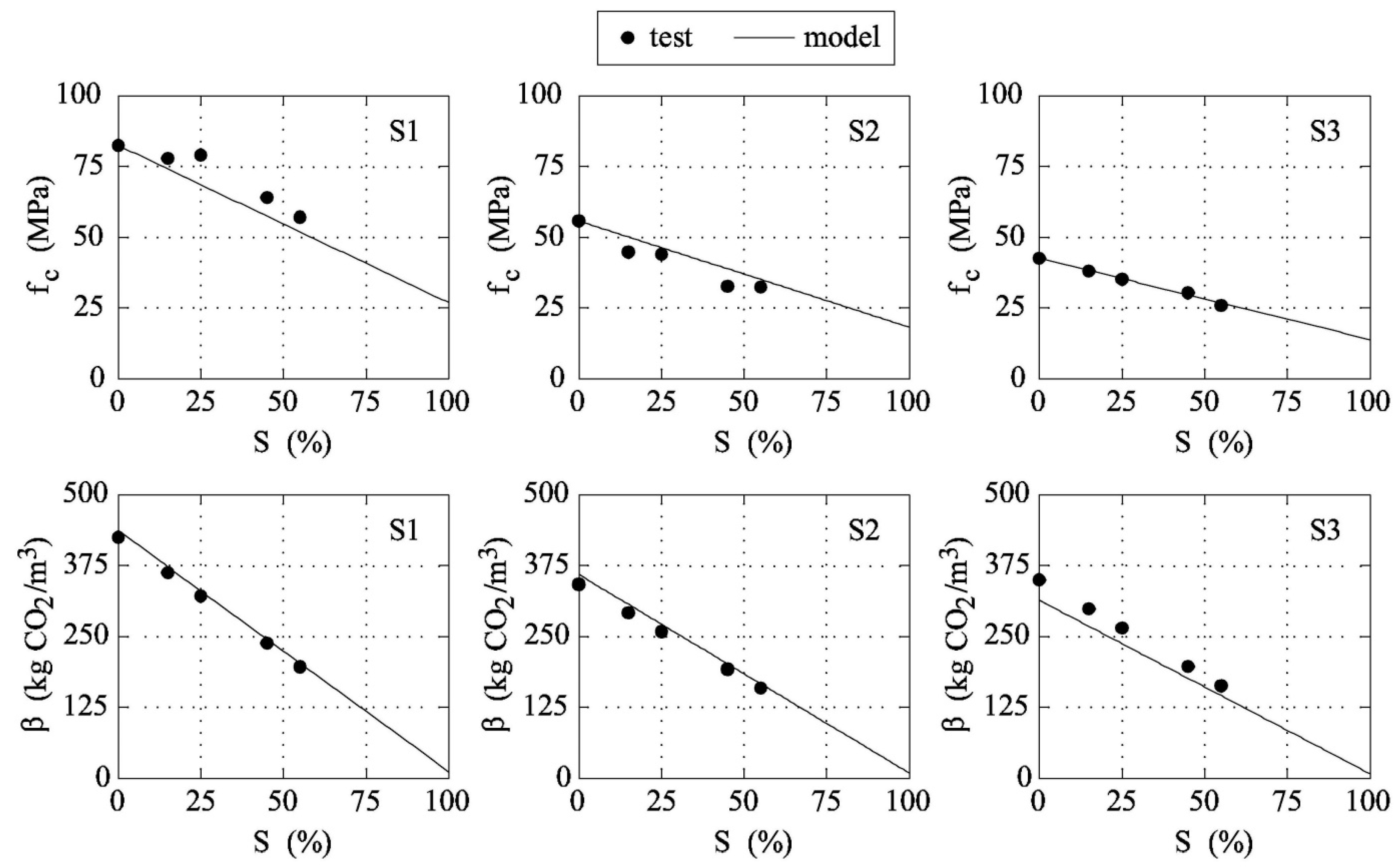
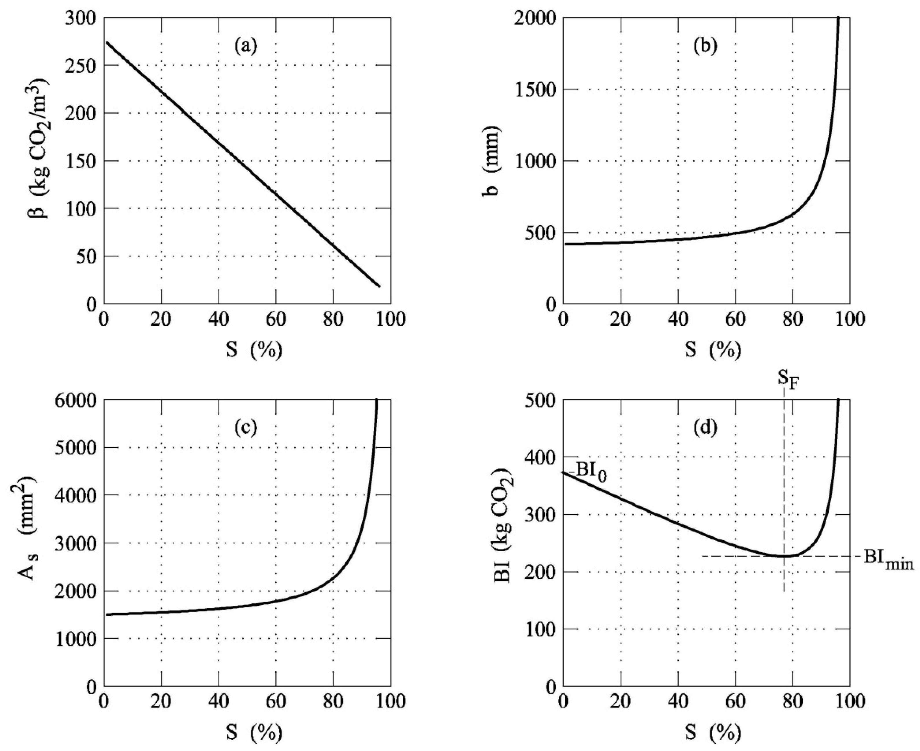
As shown in
Figure 3,
β (and thus
fc) linearly decreases with
S (see also
Figure 6a). Consequently, the geometrical dimensions of the beam increase as the substitution rate of cement with fly ash increases. As a matter of fact, the width of the beam
b becomes larger as
S grows. Nevertheless, the
b-
S function (
Figure 6b) is not linear as is
β-
S (
Figure 6a). In particular, when
S > 75% the width of the beam drastically increases for small increments of
S, and
Figure 6b shows a vertical asymptote when
S → 100%.
The above observations are also valid for the area of the steel used to reinforce the tensile zone of the RC beam. Namely,
Figure 6c reveals a monotonic increment of
As with
S, but the
As-
S function shows two different slopes before and after
S ≅ 75% (
Figure 6c). As a result, the global impact of an RC beam decreases when
S < 75%, whereas
BI grows when
S > 75% (
Figure 6d). In other words, although the unitary impact of concrete always decreases with
S (see
Figure 6a), the global impact of a beam
BI is not a monotonic function of
S (see
Figure 6d). For the given initial strength and impact (i.e.,
fcA and
BI0), the values of
BI have a minimum,
BImin, in correspondence to the substitution rate
SF (where 0 <
SF < 100%).
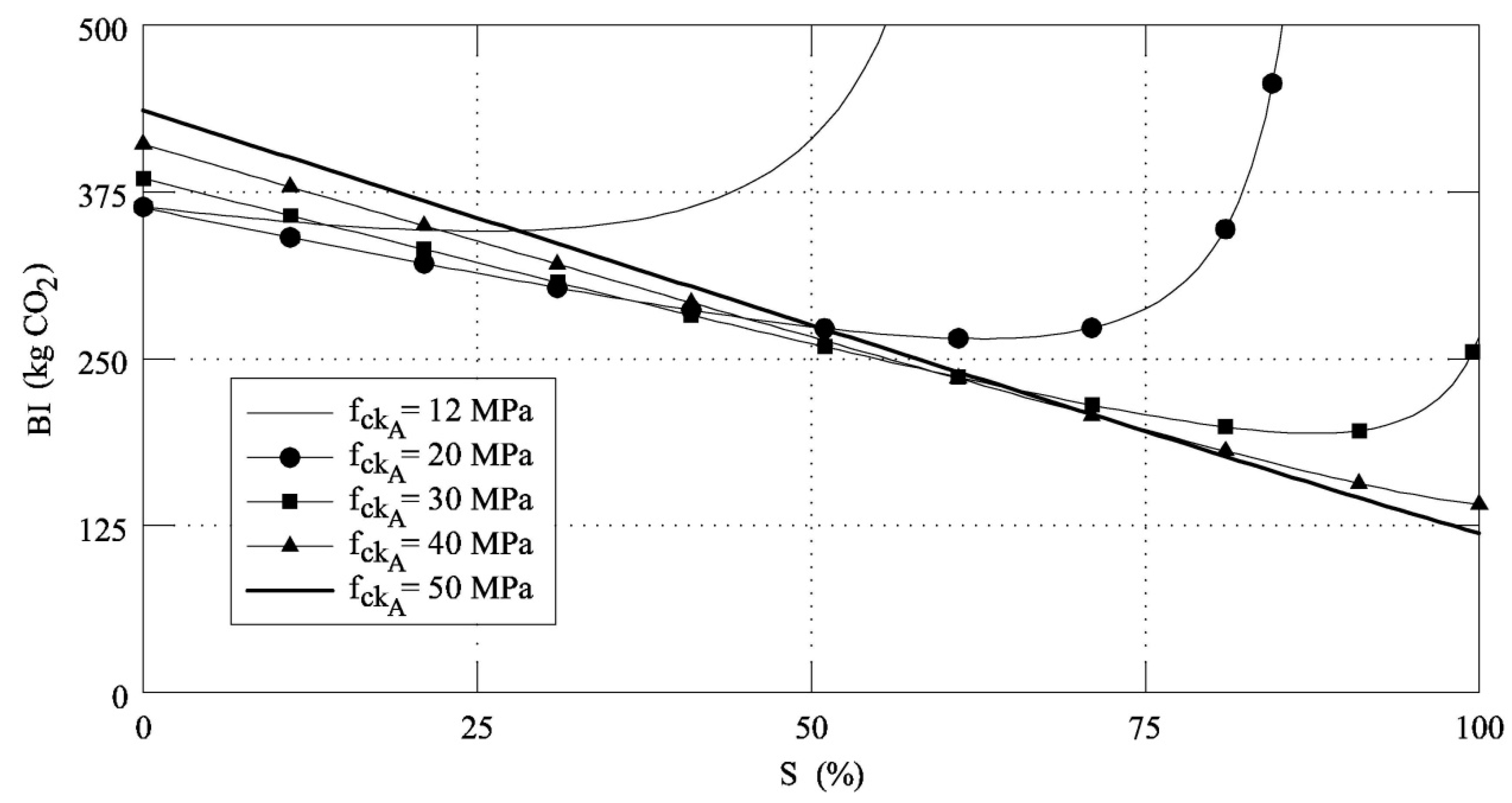
It must be noted that the shape of the functions
BI-
S strongly depends on
fckA. As shown in
Figure 7, where five
BI-
S functions, corresponding to five different values of
fckA, are reported,
BImin tends to decrease and
SF tends to increase if the initial strength of the concrete increases. However,
BI0 becomes larger as
fckA increases, and, when
S <
SF, although the beam can be cast with a low amount of concrete (and steel, as well), the impact is higher due to the high content of cement. On the contrary, when
S >
SF, the impact increases despite the low amount of cement (and low concrete strength), because large amounts of concrete and steel are needed. Finally, the proposed model reveals that for high values of
fckA, the best substitution rate of cement with fly ash can be 100% (i.e.,
SF = 100%).
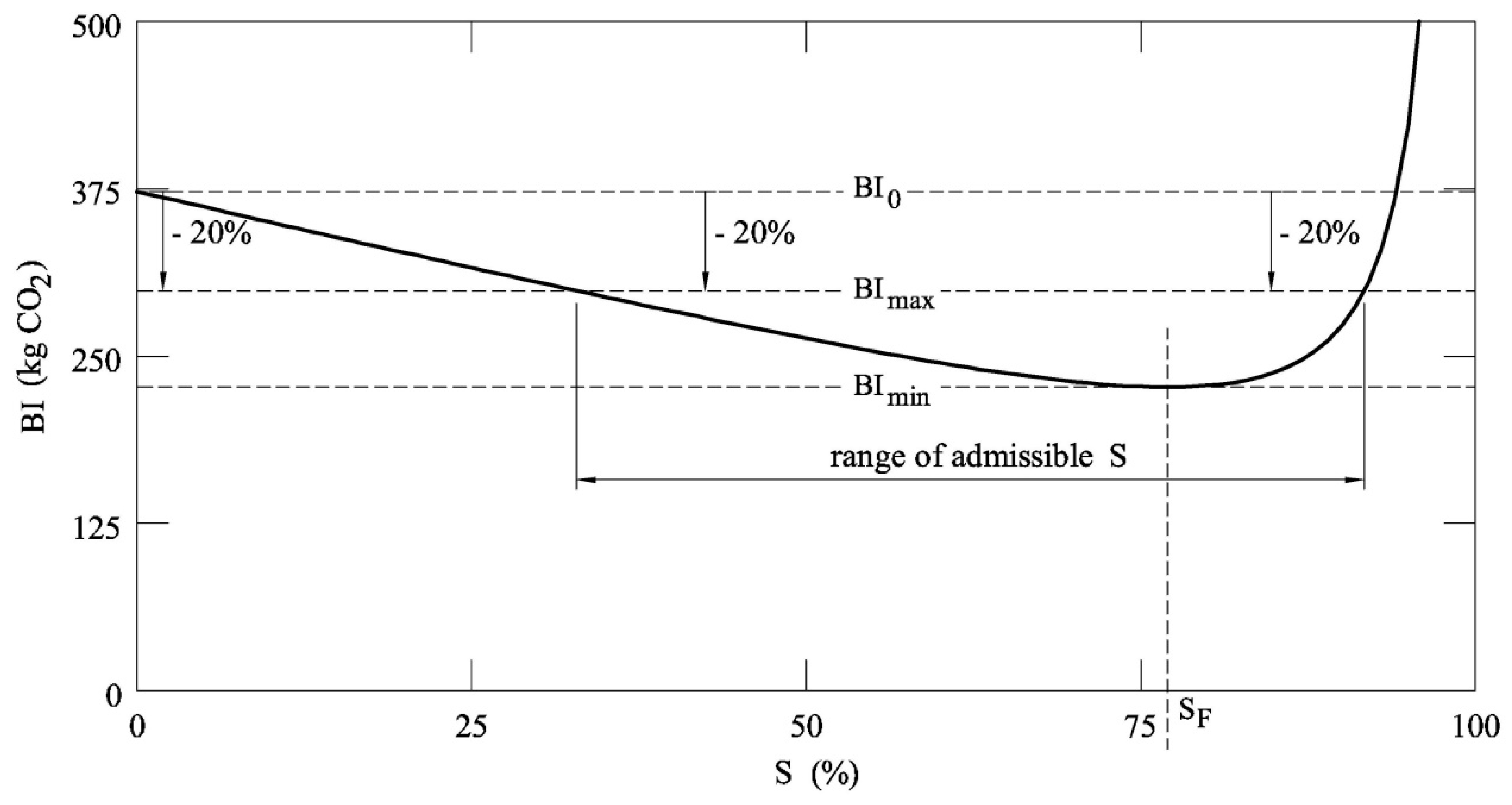
From a practical point of view, the substitution rate cannot be too high, because some problems occur in the concrete system, whose early strength decreases with
S [
13]. Thus, to reduce the emission of CO
2, a new limit state of sustainability, corresponding to the maximum environmental impact of a structure, is herein introduced. For instance, code rules or tenders can require a concrete in which the substitution of cement with fly ashes leads to a reduction of the carbon dioxide emission of larger than 20% (as suggested in [
9]), with respect to the emission produced by the same concrete system when
S = 0. Referring to
Figure 8, where the concrete strength
fckA is 25 MPa, a new limit
BImax = 80%
BI0 must be introduced. It defines a range of the admissible
S, where the optimal substitution rate of cement with fly ash (or others SCMs) can be selected. The best
S does not necessarily coincide with
SF, because, for large substitutions, the RC beams and the area of rebar are too large to be used in practice. Moreover, higher rates of substitution would provide a decrease in the early strength of concrete. Thus, some building codes impose lower limits on the usage rates of fly ash than the feasibility rates measured by laboratory tests.
Finally, it must be noted that though the proposed approach herein applies to fly ashes only, it can be easily generalized to other SCMs. Indeed, the procedure illustrated in
Figure 5 can be used in all cases, if the parameters of Equations (2) and (3) are experimentally measured for the supplementary cementitious material taken into consideration.


