Influence of Boron Additions and Heat Treatments on the Fatigue Resistance of CoCrMo Alloys

 ,
,  , , and
Abstract
:1. Introduction
2. Materials and Methods
2.1. Materials
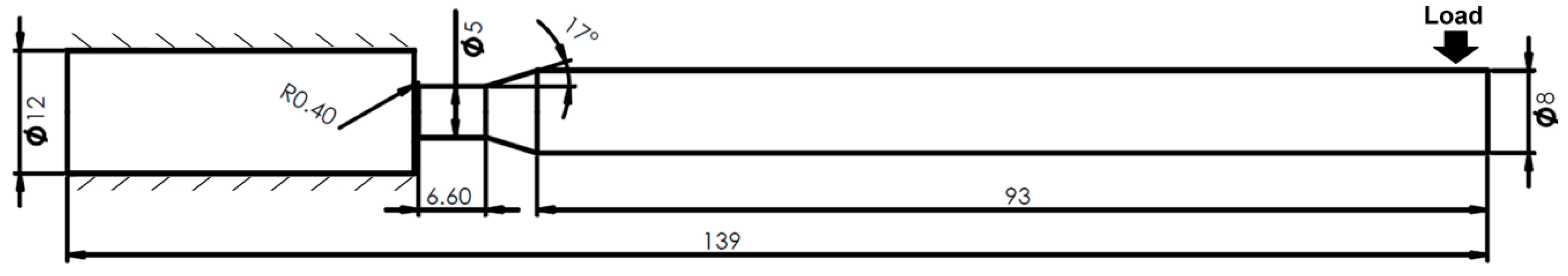
2.2. Specimens and Equipment
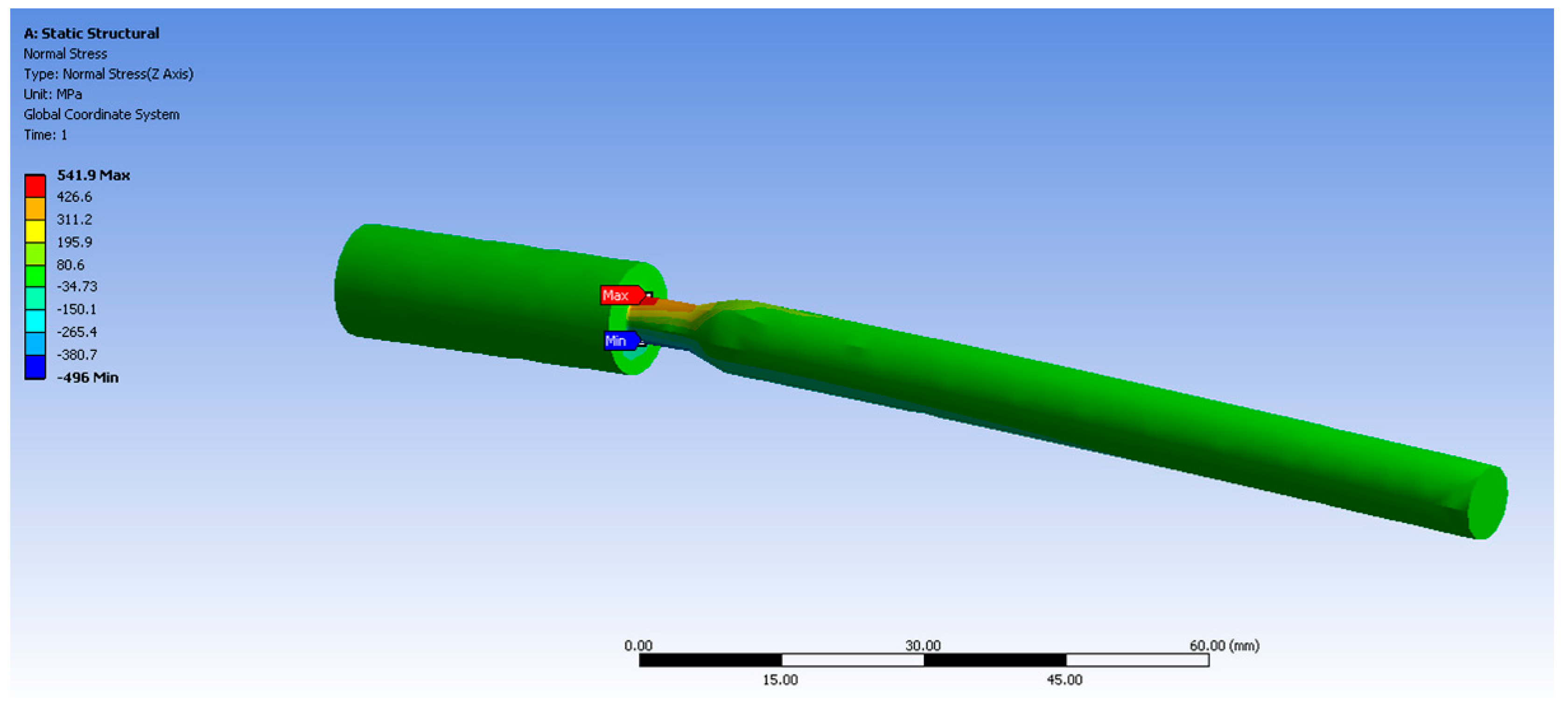
2.3. Stress and Stress Concentration Factor
2.4. Experimental Procedure
3. Results
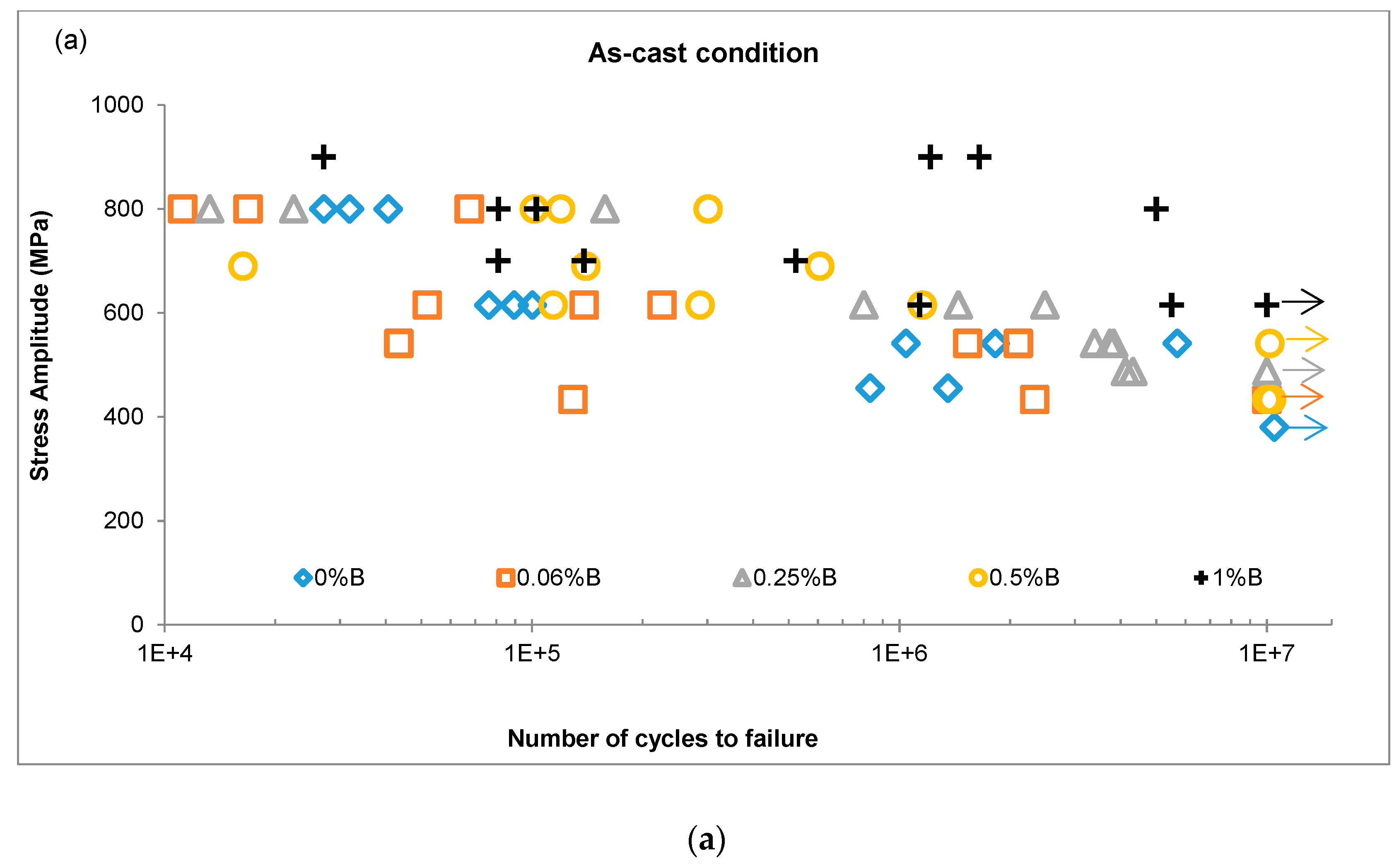
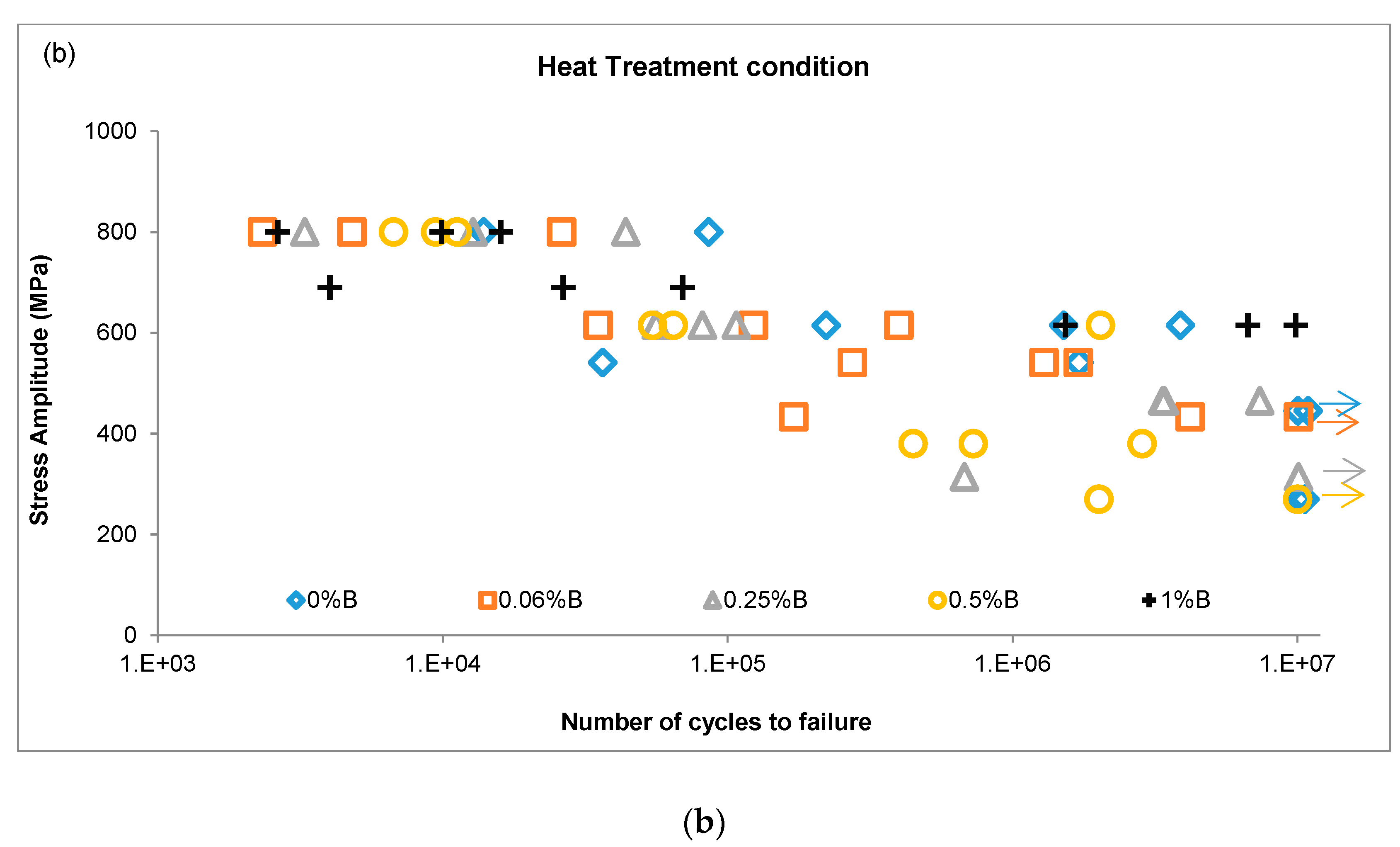
3.1. S-N Curves
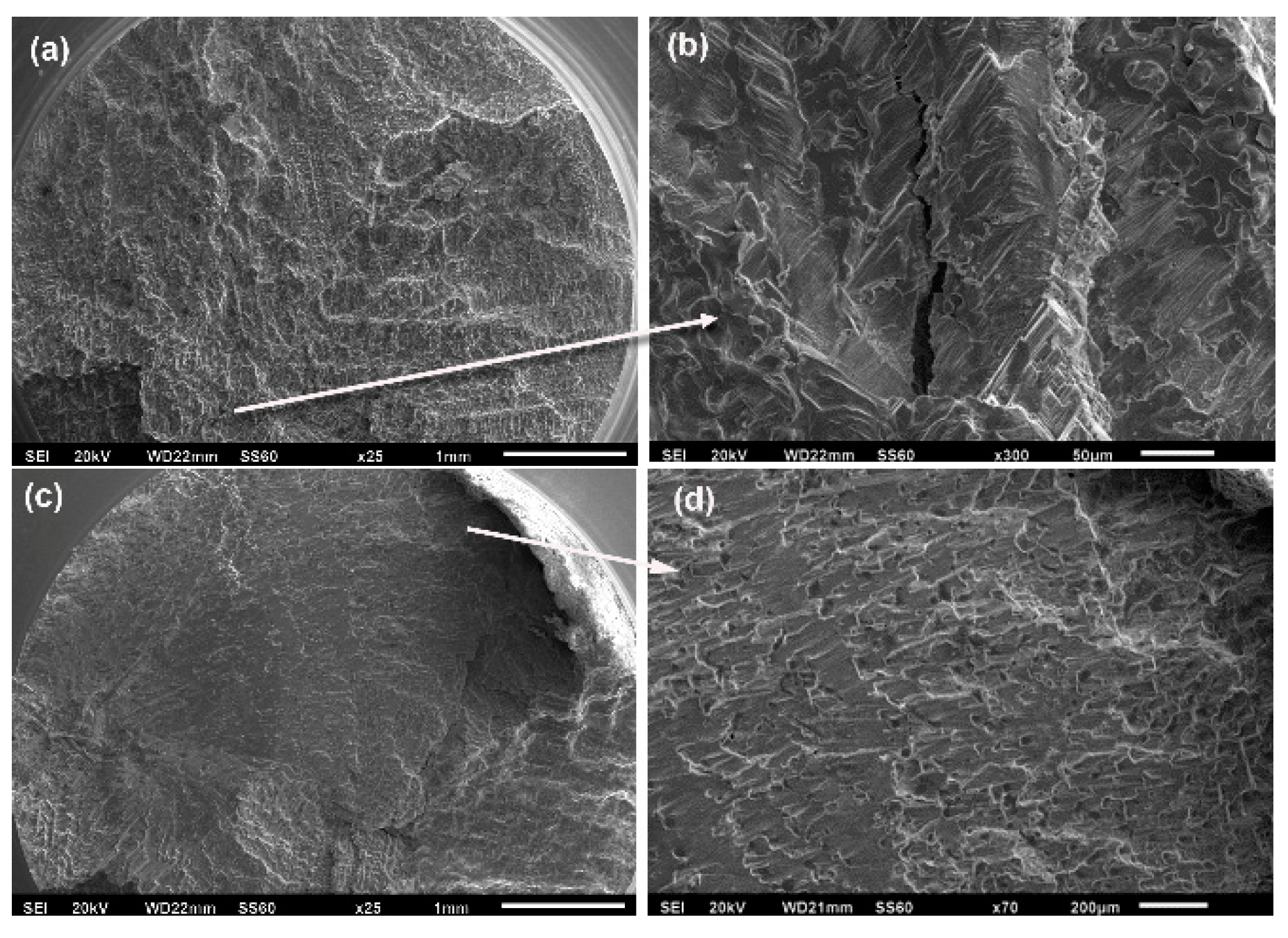
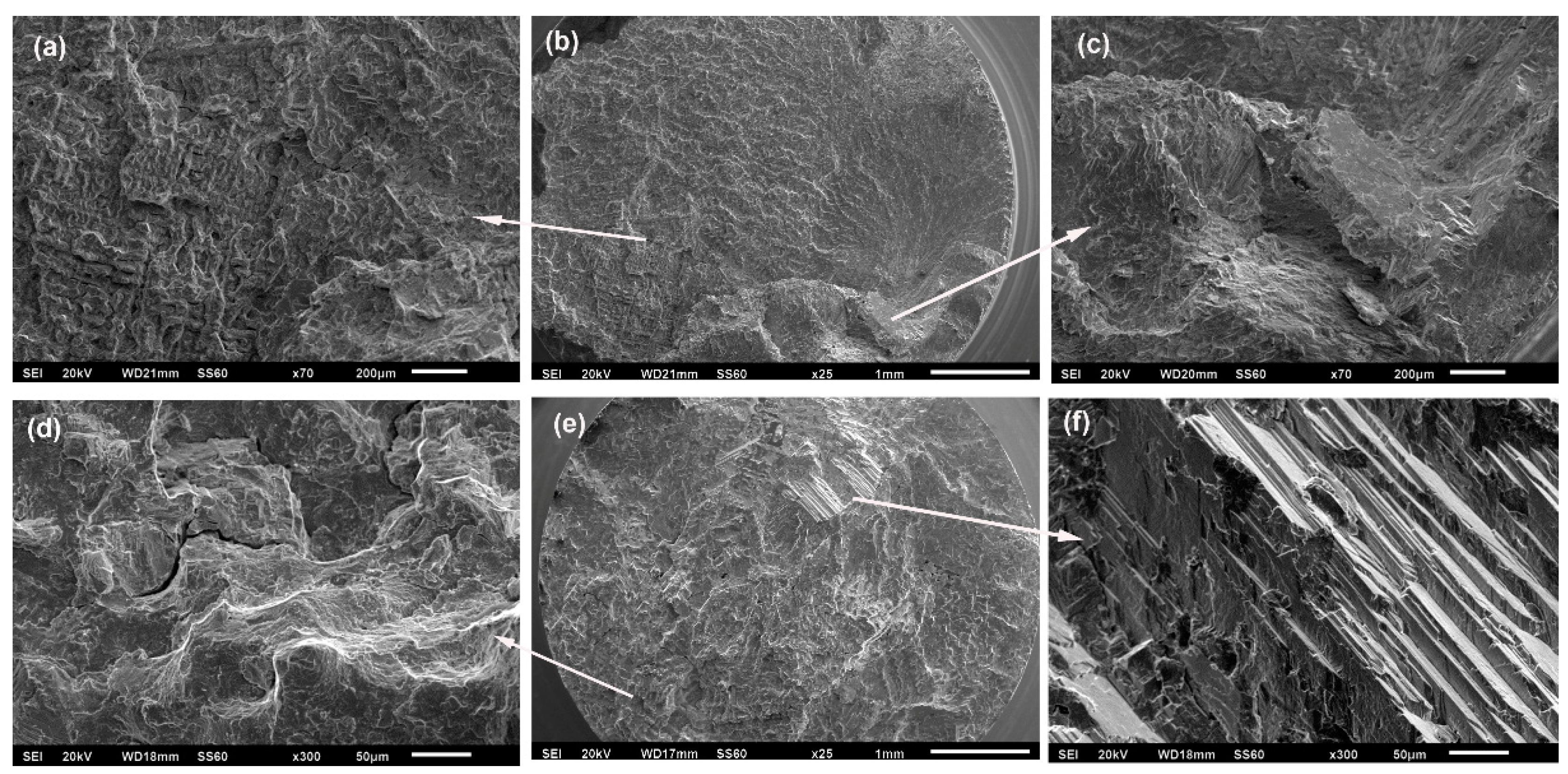
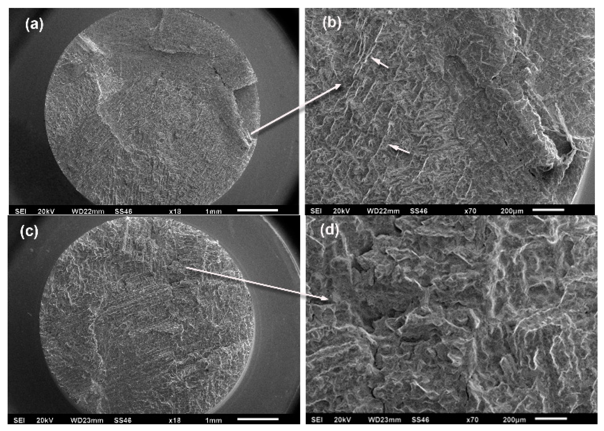
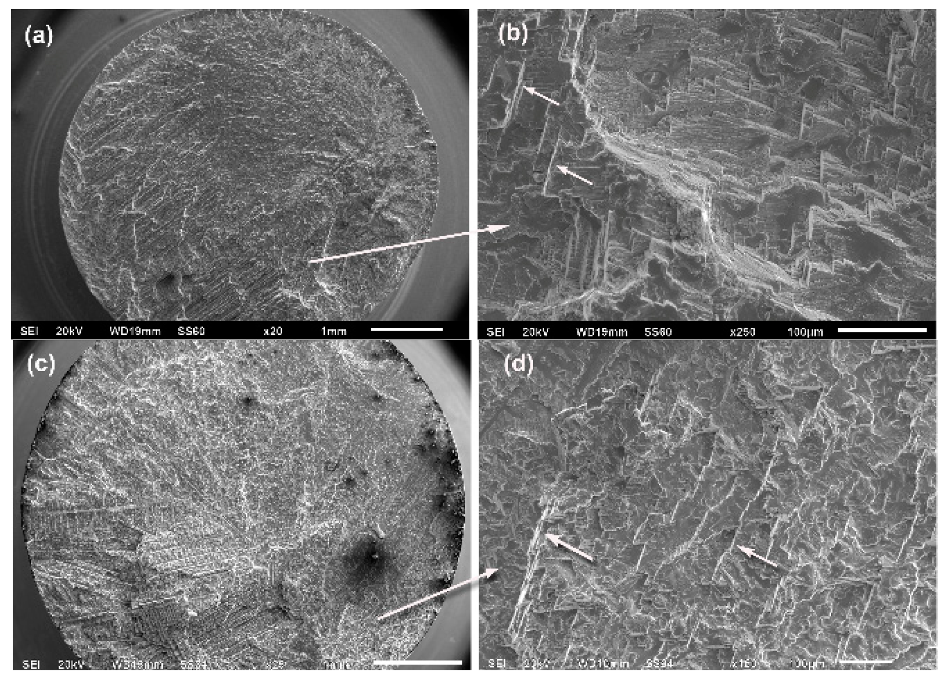
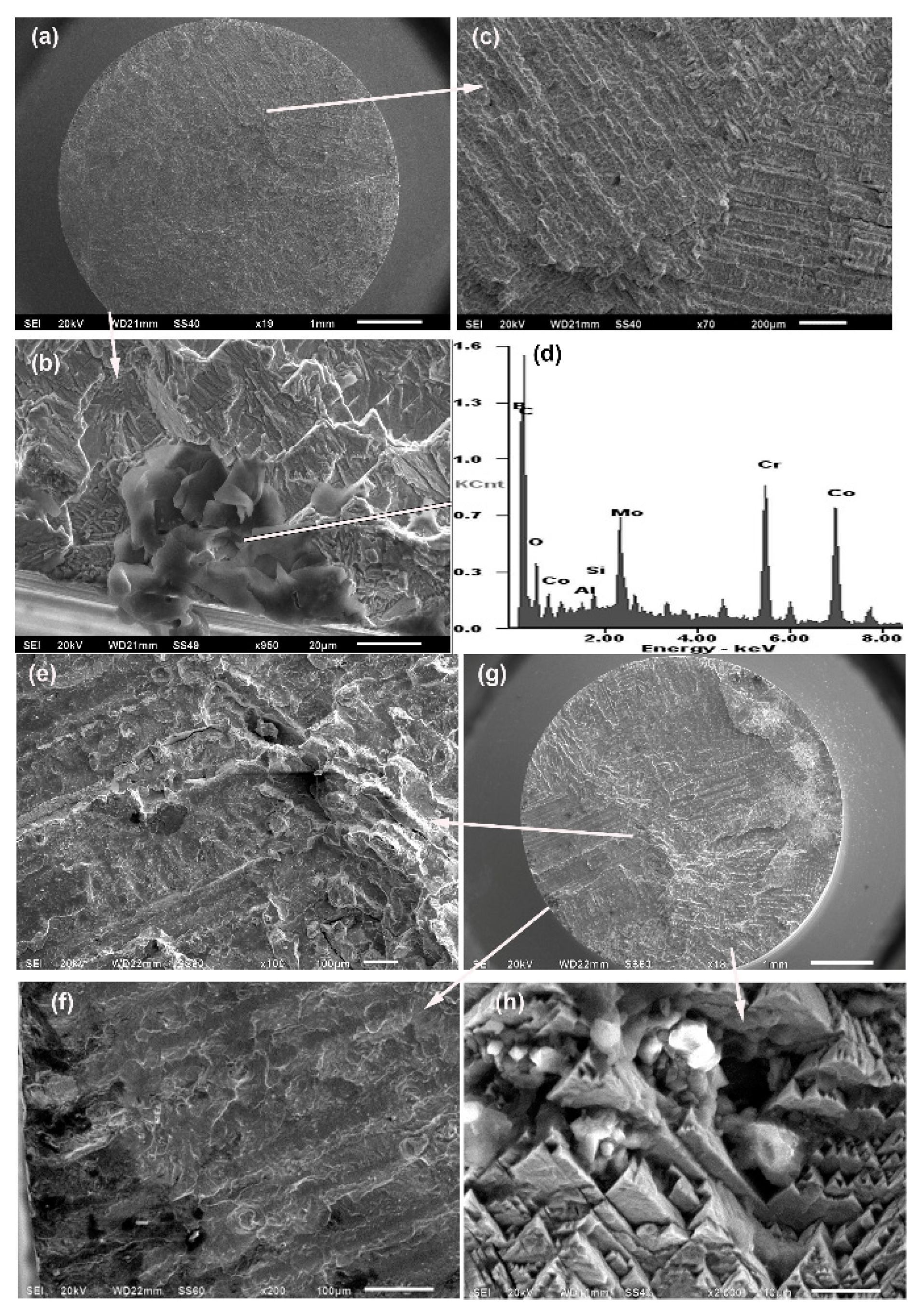
3.2. Fatigue Crack Surfaces
4. Conclusions
Author Contributions
Funding
Conflicts of Interest
References
- Niinomi, M.; Nakai, M.; Hieda, J. Development of new metallic alloys for biomedical applications. Acta Biomater. 2012, 8, 3888–3903. [Google Scholar] [CrossRef]
- Hanawa, T. Metal ion release from metal implants. Mater. Sci. Eng. C 2004, 24, 745–752. [Google Scholar] [CrossRef]
- Hanawa, T. Evaluation techniques of metallic biomaterials in vitro. Sci. Technol. Adv. Mater. 2002, 3, 289–295. [Google Scholar] [CrossRef]
- Manivasagam, G.; Dhinasekaran, D.; Rajamanickam, A. Biomedical Implants: Corrosion and its Prevention-A Review. Recent Pat. Corros. Sci. 2010, 2, 40–54. [Google Scholar]
- Geetha, M.; Singh, A.K.; Asokamani, R.; Gogia, A.K. Ti based biomaterials, the ultimate choice for orthopaedic implants–A review. Prog. Mater. Sci. 2009, 54, 397–425. [Google Scholar] [CrossRef]
- Haghighi, S.E.; Lu, H.B.; Jian, G.Y.; Cao, G.H.; Habibi, D.; Zhang, L.C. Effect of α″ martensite on the microstructure and mechanical properties of beta-type Ti–Fe–Ta alloys. Mater. Des. 2015, 76, 47–54. [Google Scholar] [CrossRef]
- Ehtemam-Haghighi, S.; Liu, Y.; Cao, G.; Zhang, L.-C. Influence of Nb on the β → α″ martensitic phase transformation and properties of the newly designed Ti–Fe–Nb alloys. Mater. Sci. Eng. C 2016, 60, 503–510. [Google Scholar] [CrossRef]
- Ehtemam-Haghighi, S.; Attar, H.; Dargusch, M.S.; Kent, D. Microstructure, phase composition and mechanical properties of new, low cost Ti-Mn-Nb alloys for biomedical applications. J. Alloy. Compd. 2019, 787, 570–577. [Google Scholar] [CrossRef]
- Chen, Q.; Thouas, G.A. Metallic implant biomaterials. Mater. Sci. Eng. R Rep. 2015, 87, 1–57. [Google Scholar] [CrossRef]
- Niinomi, M. Fatigue characteristics of metallic biomaterials. Int. J. Fatigue 2007, 29, 992–1000. [Google Scholar] [CrossRef]
- Teoh, S. Fatigue of biomaterials: a review. Int. J. Fatigue 2000, 22, 825–837. [Google Scholar] [CrossRef]
- Gueler, S.; Schymura, M.; Fischer, A. Austenitic high interstitial steels vs. CoCrMo–Comparison of fatigue behavior. Int. J. Fatigue 2015, 75, 145–152. [Google Scholar] [CrossRef]
- Dempsey, A.J.; Pilliar, R.M.; Weatherly, G.C.; Kilner, T. The effects of nitrogen additions to a cobalt-chromium surgical implant alloy. J. Mater. Sci. 1987, 22, 575–580. [Google Scholar] [CrossRef]
- Sudhakar, K.V.; Wang, J. Fatigue Behavior of vitallium-2000 plus alloy for orthopedic applications. J. Mater. Eng. Perform. 2011, 20, 1023–1027. [Google Scholar] [CrossRef]
- Opiekun, Z. Kinetics of secondary carbide precipitation in boron-modified cobalt alloys of MAR-M509 type. J. Mater. Sci. 1991, 26, 3386–3391. [Google Scholar] [CrossRef]
- Zhuang, L.Z.; Langer, E.W. Effects of alloy additions on the microstructures and tensile properties of cast Co-Cr-Mo alloy used for surgical implants. J. Mater. Sci. 1989, 24, 4324–4330. [Google Scholar] [CrossRef]
- Zhuang, L.Z.; Langer, E.W. Effects of alloy additions on the fatigue properties of cast Co-Cr-Mo alloy used for surgical implants. J. Mater. Sci. 1990, 25, 683–689. [Google Scholar] [CrossRef]
- Antunes Altobelli, R.; de Oliveira Lopes, M.C. Corrosion fatigue of biomedical metallic alloys: Mechanisms and mitigation. Acta Biomater. 2012, 8, 937–962. [Google Scholar] [CrossRef]
- Dobbs, H.S.; Robertson, J.L.M. Heat treatment of cast Co-Cr-Mo for orthopaedic implant use. J. Mater. Sci. 1983, 18, 391–401. [Google Scholar] [CrossRef]
- Hernandez-Rodriguez, M.A.L.; Laverde-Cataño, D.A.; Lozano, D.E.; Martinez-Cazares, G.; Bedolla-Gil, Y. Influence of boron addition on the microstructure and the corrosion resistance of CoCrMo alloy. Metals 2019, 9, 307. [Google Scholar] [CrossRef]
- Bedolla-Gil, Y.; Juarez-Hernandez, A.; Perez-Unzueta, A.; Garcia-Sanchez, E.; Mercado-Solis, R.; Hernandez-Rodriguez, M.A.L. Influence of heat treatments on mechanical properties of a biocompatility alloy ASTM F75. Rev. Mex. Fis. 2009, 55, 1–5. [Google Scholar]
- Bedolla-Gil, Y.; Hernandez-Rodriguez, M.A.L. Tribological Behavior of a Heat-Treated Cobalt-Based Alloy. J. Mater. Eng. Perform. 2013, 22, 541–547. [Google Scholar] [CrossRef]
- Martinez-Cazares, G.; Mercado-Solis, R.; Bedolla-Gil, Y.; Lozano, D.E. Continuous estimation of the crack growth rate during rotating‒bending fatigue testing. Metals 2019, 9, 275. [Google Scholar] [CrossRef]
- Manson, S.S.; Halford, G.R. Fatigue and Durability of Structural Materials; ASM International: Almere, The Netherlands, 2006; ISBN 0871708256. [Google Scholar]
- Sudhakar, K.V. Investigation of failure mechanism in vitallium 2000 implant. Eng. Fail. Anal. 2005, 12, 257–262. [Google Scholar] [CrossRef]
- ASTM F75-07Standard Specification for Cobalt-28 Chromium-6 Molybdenum Alloy Castings and Casting Alloy for Surgical Implants (UNS R30075); ASTM International: West Conshohocken, PA, USA, 2007.
- Ahmad, M.; Xu, Y.B.; Yao, G.; Hu, Z.Q. Fatigue crack growth of DSX40M alloy at ambient and elevated temperatures. J. Mater. Sci. 2002, 37, 2279–2292. [Google Scholar] [CrossRef]


| Cr | Mo | C | Si | Fe | B | Co |
|---|---|---|---|---|---|---|
| 27–30 | 8–11 | 0.08–0.26 | 0.17–0.74 | 0.3–0.8 | 0–1 | balance |
| %B | 0 | 0.06 | 0.25 | 0.5 | 1 |
|---|---|---|---|---|---|
| As-cast | 0B-AC | 0.06B-AC | 0.25B-AC | 0.5B-AC | 1B-AC |
| Heat treated | 0B-HT | 0.06B-HT | 0.25B-HT | 0.5B-HT | 1B-HT |
| Material | As-Cast | Heat Treated | ||
|---|---|---|---|---|
| N | NCP | N | NCP | |
| 0B | 100,120 | 7400 | 3,879,407 | 2500 |
| 0.06B | 226,129 | 2700 | 398,440 | 31,500 |
| 0.25B | 799,846 | 7900 | 107,191 | 3000 |
| 0.5B | 1,153,988 | 3200 | 2,033,481 | 1600 |
| 1B | 5,507,500 | 2900 | 9,849,976 | 900 |
© 2019 by the authors. Licensee MDPI, Basel, Switzerland. This article is an open access article distributed under the terms and conditions of the Creative Commons Attribution (CC BY) license (http://creativecommons.org/licenses/by/4.0/).
Share and Cite
Hernandez-Rodriguez, M.A.L.; Mercado-Solis, R.D.; Presbítero, G.; Lozano, D.E.; Martinez-Cazares, G.M.; Bedolla-Gil, Y. Influence of Boron Additions and Heat Treatments on the Fatigue Resistance of CoCrMo Alloys. Materials 2019, 12, 1076. https://doi.org/10.3390/ma12071076
Hernandez-Rodriguez MAL, Mercado-Solis RD, Presbítero G, Lozano DE, Martinez-Cazares GM, Bedolla-Gil Y. Influence of Boron Additions and Heat Treatments on the Fatigue Resistance of CoCrMo Alloys. Materials. 2019; 12(7):1076. https://doi.org/10.3390/ma12071076
Chicago/Turabian StyleHernandez-Rodriguez, Marco A. L., Rafael D. Mercado-Solis, Gerardo Presbítero, Diego E. Lozano, Gabriela M. Martinez-Cazares, and Yaneth Bedolla-Gil. 2019. "Influence of Boron Additions and Heat Treatments on the Fatigue Resistance of CoCrMo Alloys" Materials 12, no. 7: 1076. https://doi.org/10.3390/ma12071076
APA StyleHernandez-Rodriguez, M. A. L., Mercado-Solis, R. D., Presbítero, G., Lozano, D. E., Martinez-Cazares, G. M., & Bedolla-Gil, Y. (2019). Influence of Boron Additions and Heat Treatments on the Fatigue Resistance of CoCrMo Alloys. Materials, 12(7), 1076. https://doi.org/10.3390/ma12071076