A Study on the Thermal Effect by Multi Heat Sources and Machining Characteristics of Laser and Induction Assisted Milling


Abstract
1. Introduction
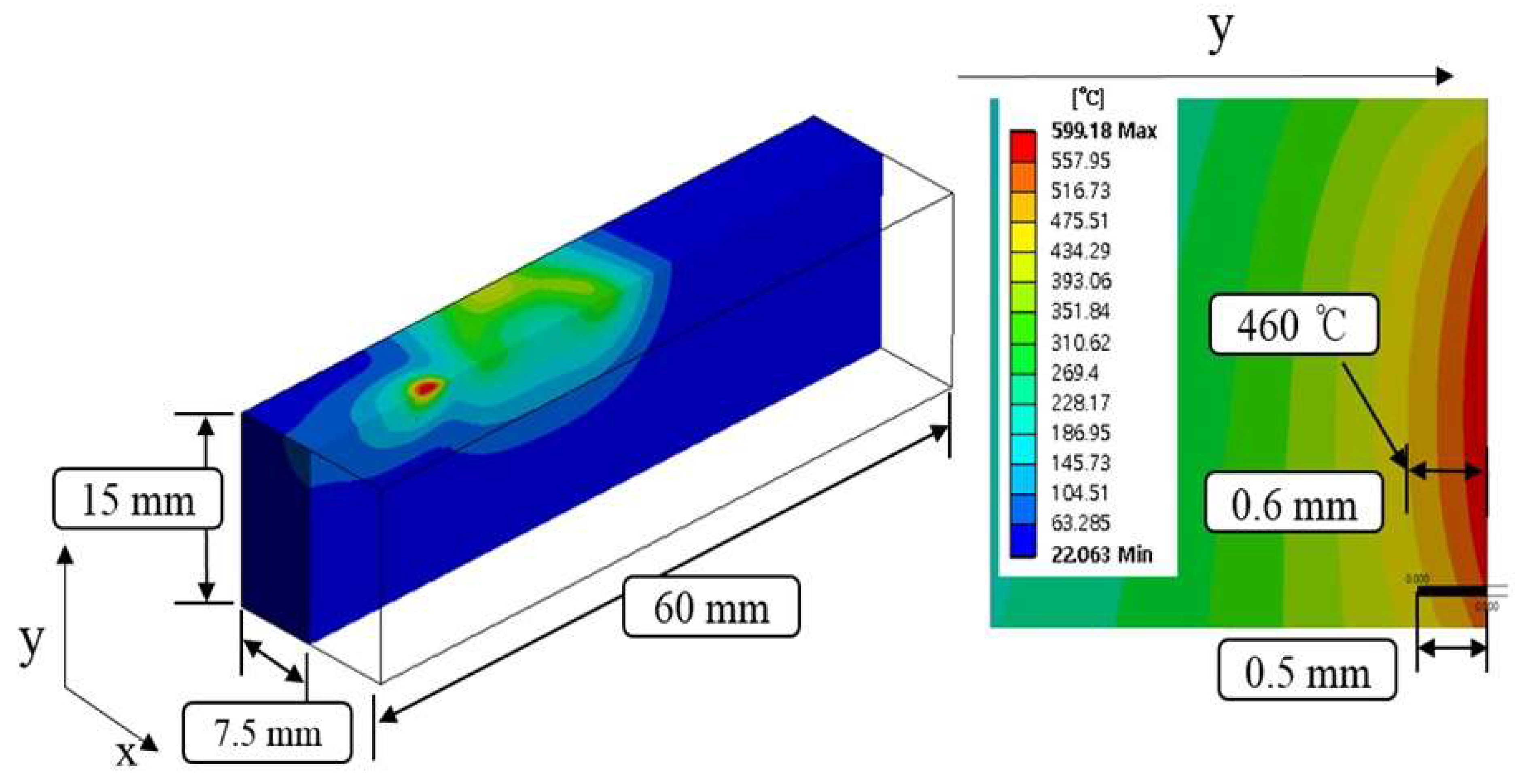
2. Thermal Analysis
2.1. Analysis Conditions
2.2. Thermal Analysis Results
2.2.1. Inconel 718
2.2.2. Ti-6Al-4V
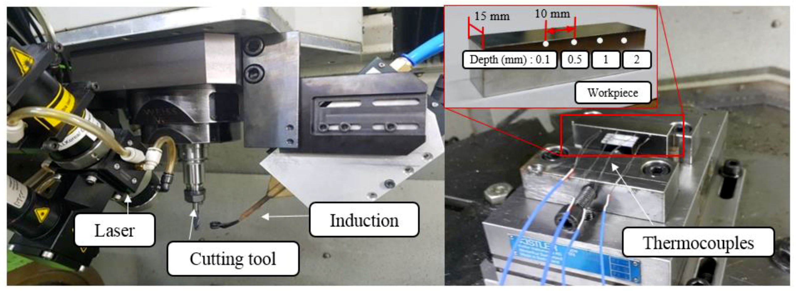
3. Thermal Measurement Experiment
3.1. Experimental Set-Up
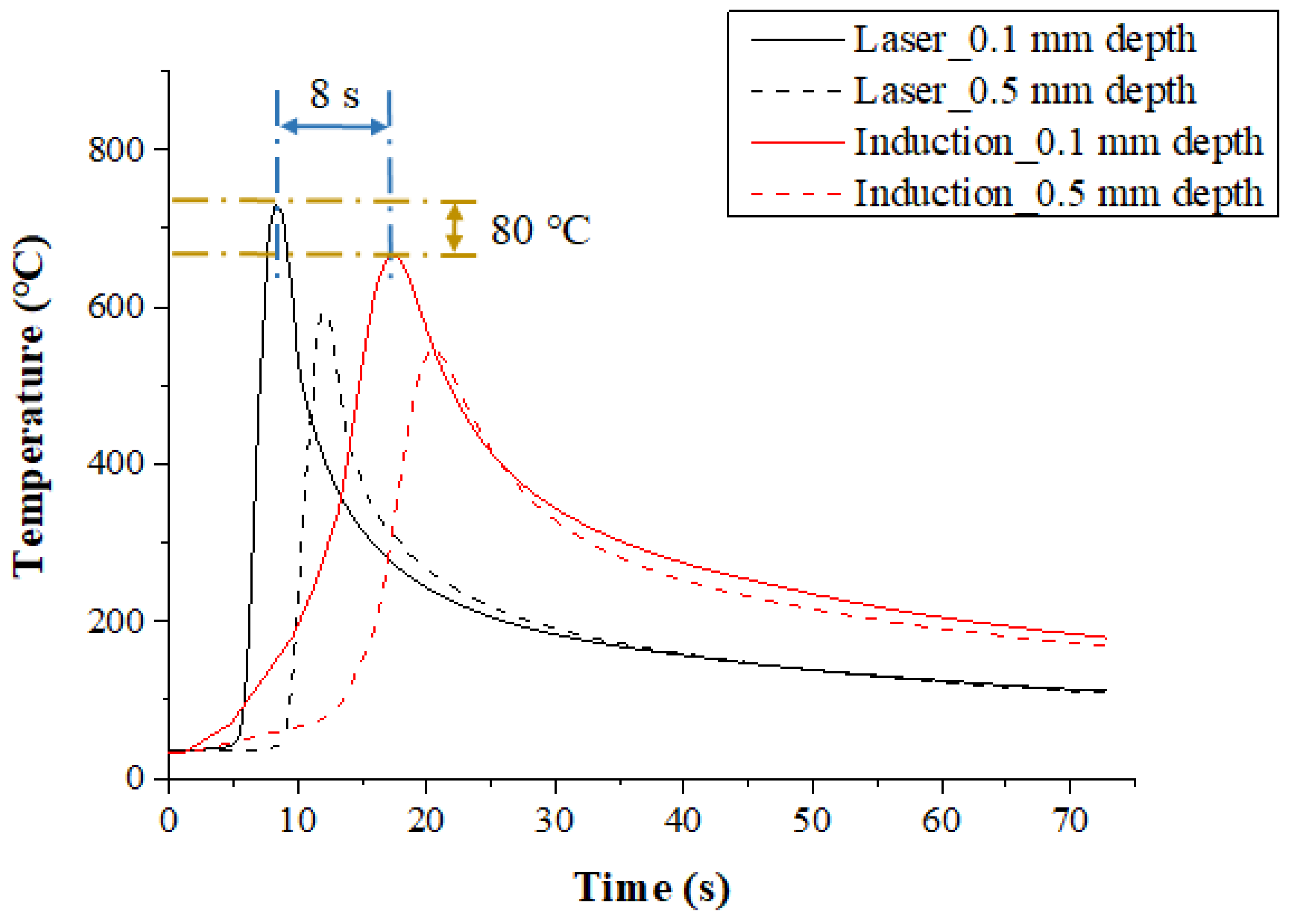
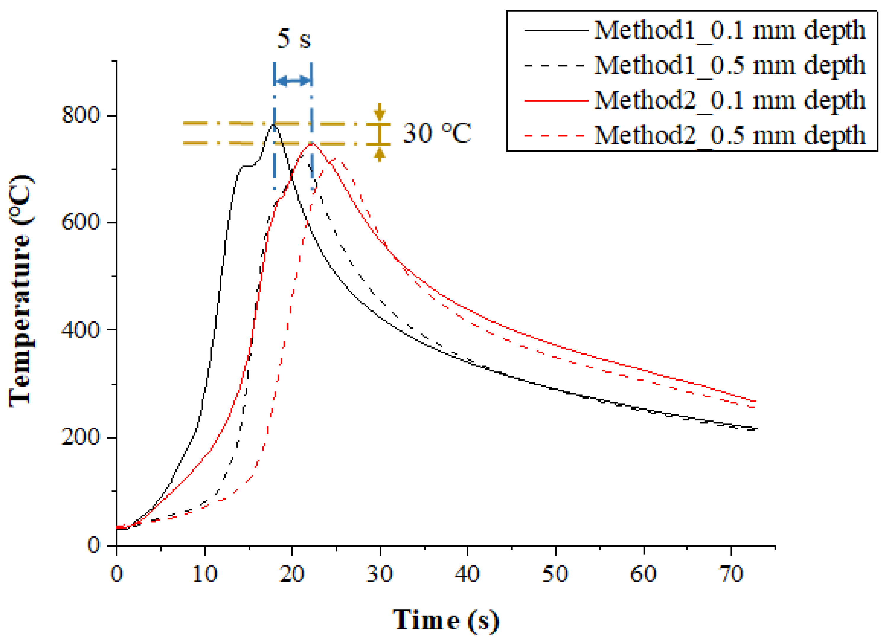
3.2. Results and Discussion
3.2.1. Inconel 718
3.2.2. Ti-6Al-4V
3.3. Comparison of the Thermal Analysis and Measurements Experiment Results
3.3.1. Inconel 718
3.3.2. Ti-6Al-4V
4. Thermally Assisted Machining
4.1. Experimental Set-Up
4.2. Inconel 718
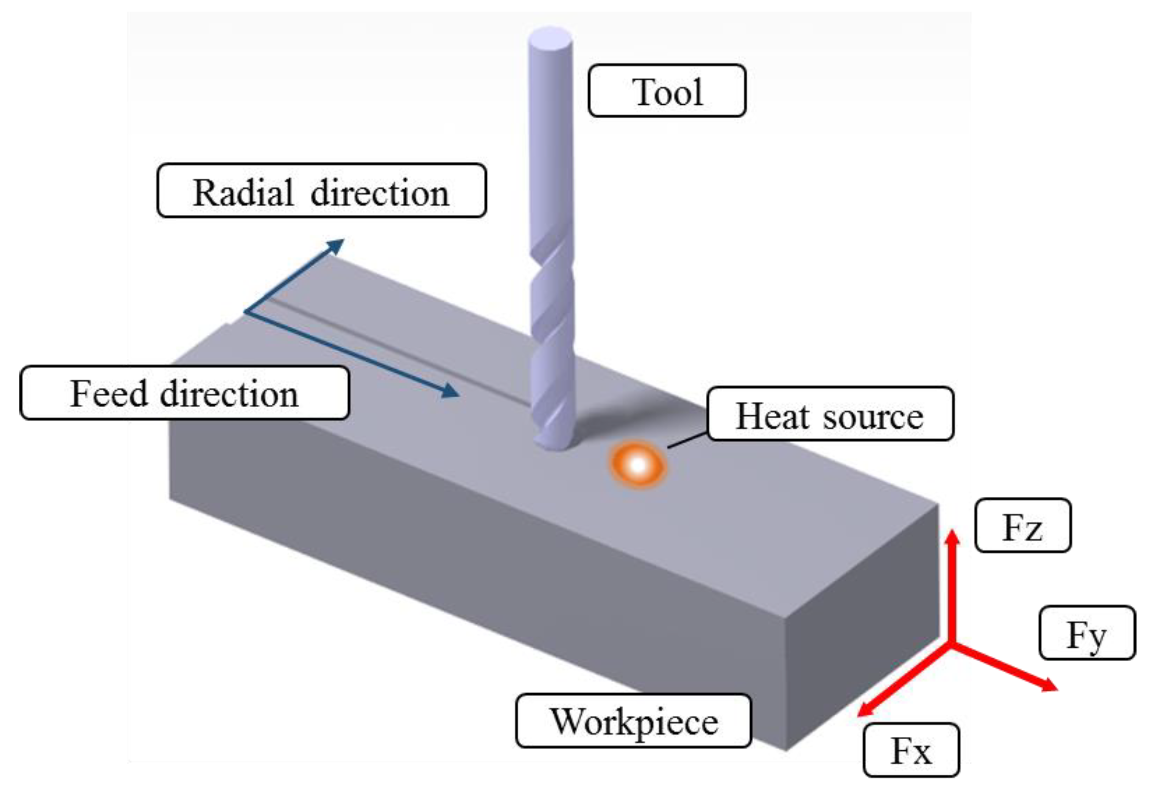
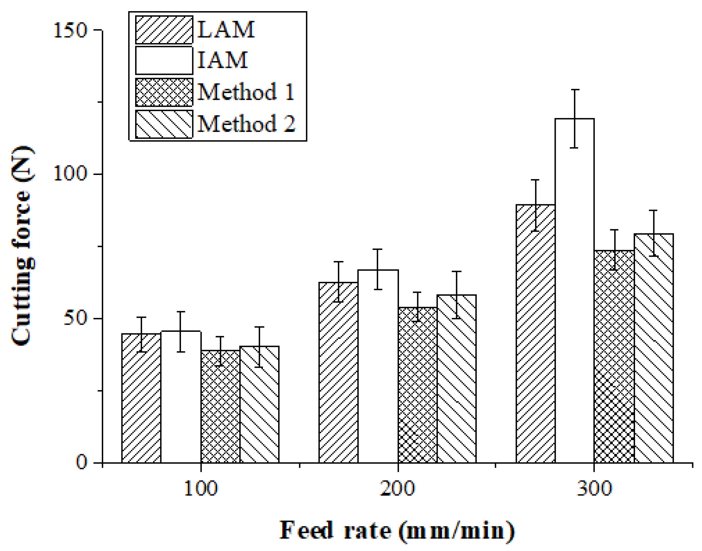
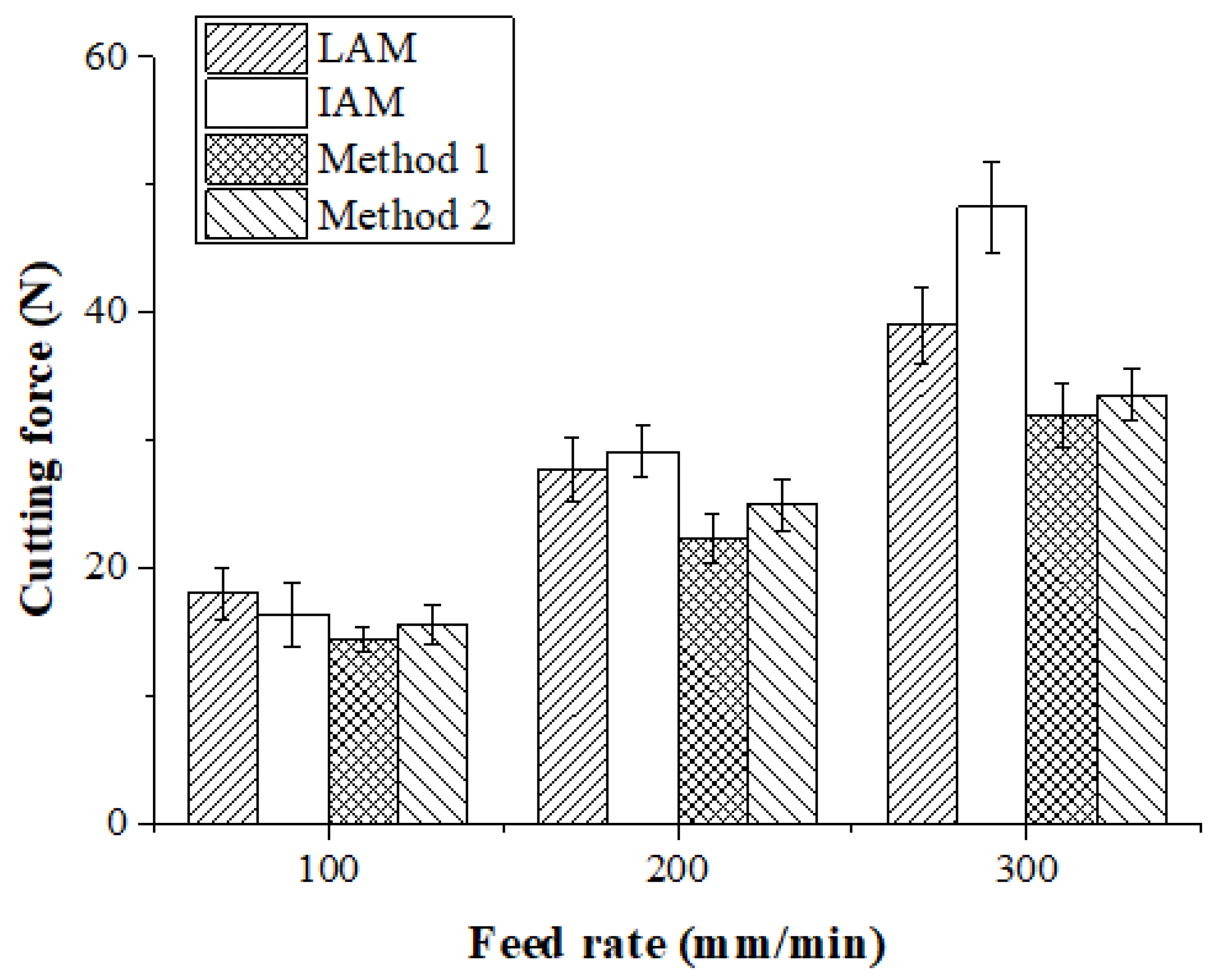
4.2.1. Cutting Forces
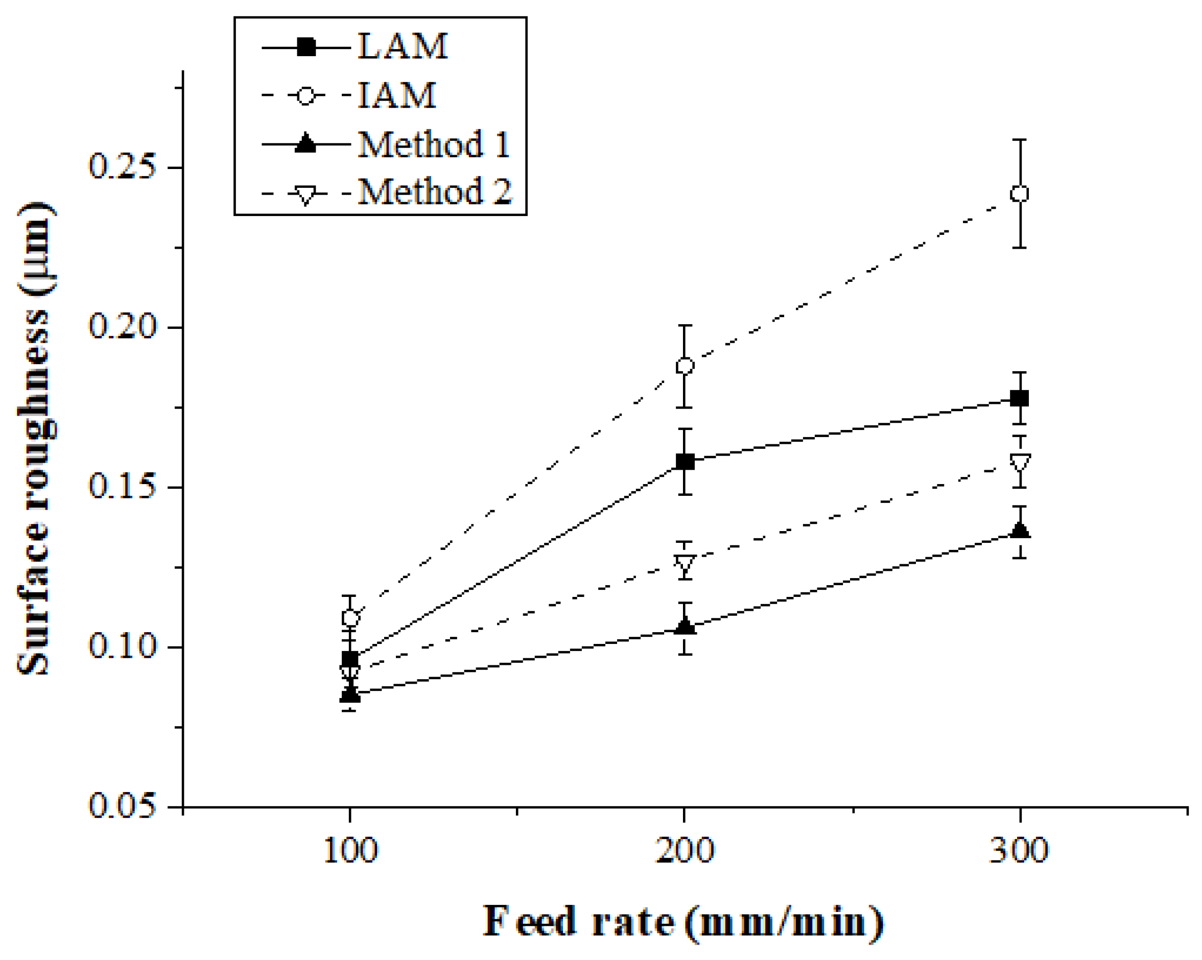
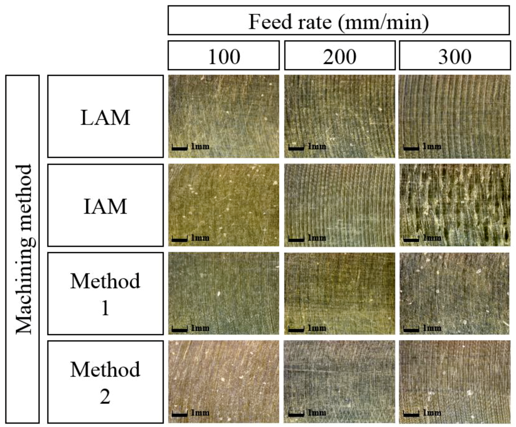
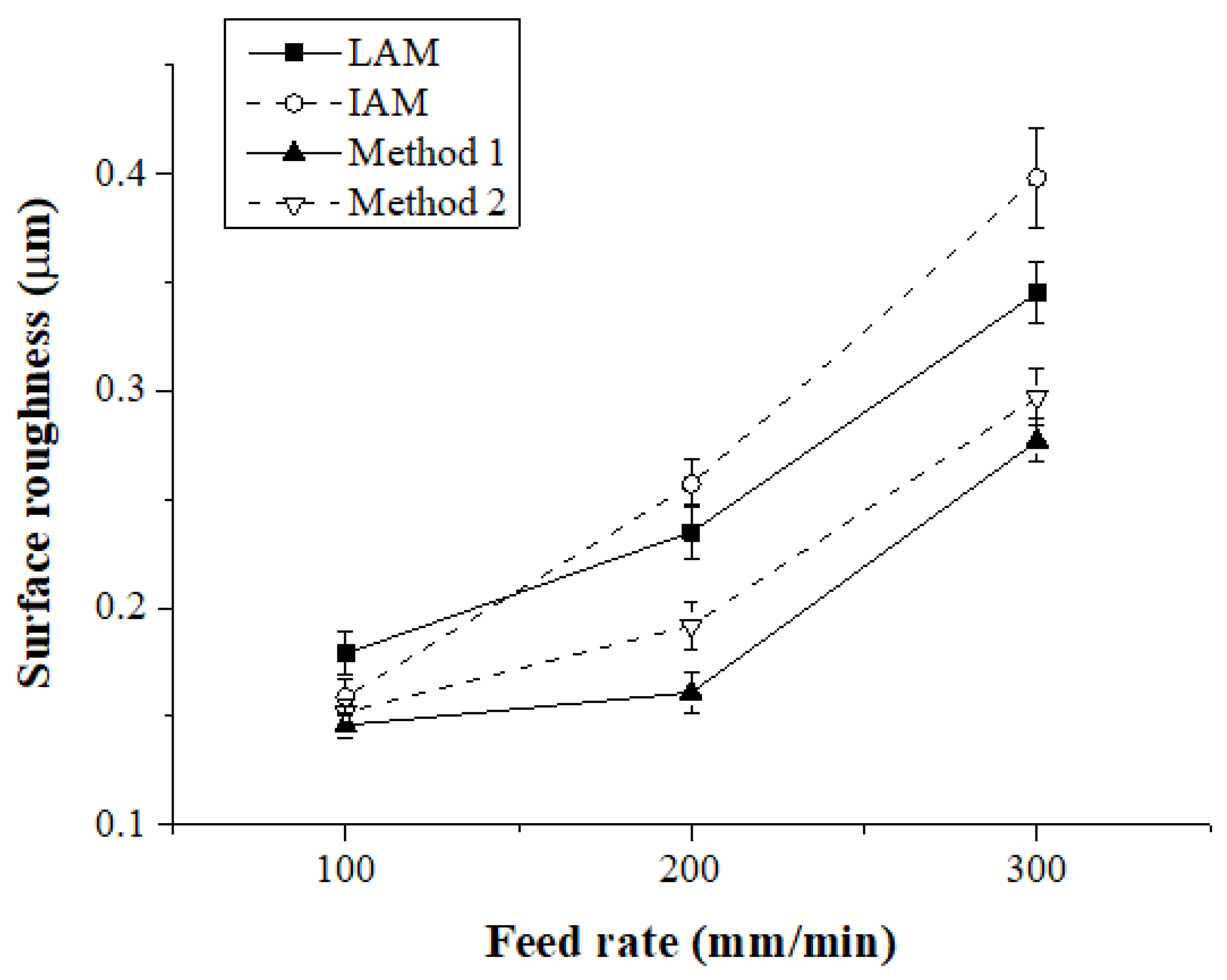
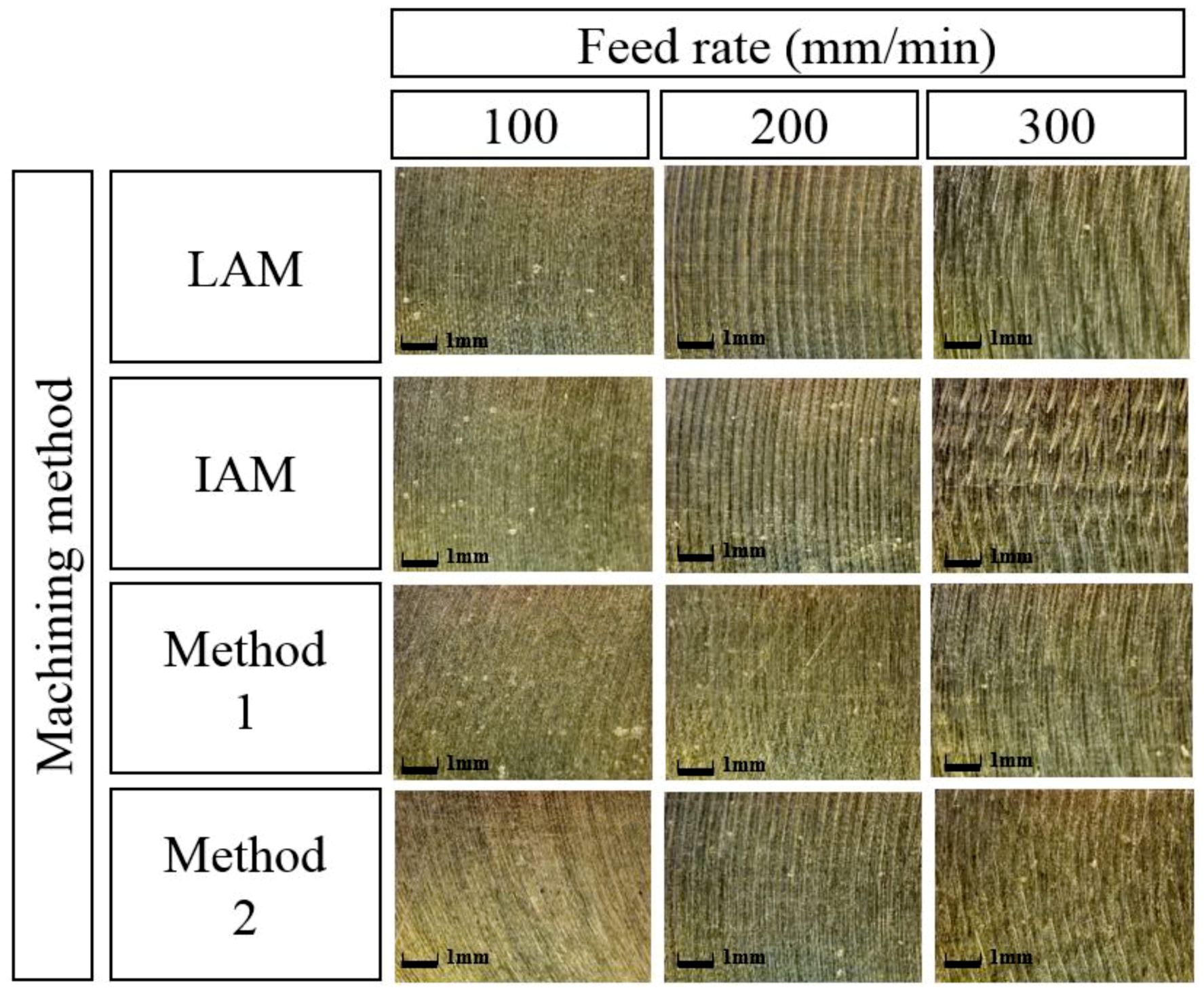
4.2.2. Surface Roughness
4.3. Ti-6Al-4V
4.3.1. Cutting Forces
4.3.2. Surface Roughness
5. Conclusions
Author Contributions
Funding
Acknowledgments
Conflicts of Interest
References
- Lee, H.; Lim, C.H.J.; Low, M.J.; Tham, N.; Murukeshan, V.M.; Kim, Y.-J. Lasers in additive manufacturing: A review. Int. J. Precis. Eng. Manuf.-Gr. Technol. 2017, 4, 307–322. [Google Scholar] [CrossRef]
- Pattanayak, S.; Panda, S. Laser Beam Micro Drilling–A Review. Lasers Manuf. Mater. Process. 2018, 4, 336–394. [Google Scholar] [CrossRef]
- Shelton, J.A.; Shin, Y.C. Comparative evaluation of laser-assisted micro-milling for AISI 316, AISI 422, TI-6AL-4V and Inconel 718 in a side-cutting configuration. J. Micromech. Microeng. 2010, 20, 075012. [Google Scholar] [CrossRef]
- Xiao, H.; Li, S.; Han, X.; Mazumder, J.; Song, L. Laves phase control of Inconel 718 alloy using quasi-continuous-wave laser additive manufacturing. Mater. Des. 2017, 122, 330–339. [Google Scholar] [CrossRef]
- Guimaraes, A.A.; Jonas, J.J. Recrystallization and aging effects associated with the high temperature deformation of Waspaloy and Inconel 718. Metall. Trans. A. 1981, 12, 1655–1666. [Google Scholar] [CrossRef]
- Ayed, Y.; Germain, G.; Ben Salem, W.; Hamdi, H. Experimental and numerical study of laser-assisted machining of Ti6Al4V titanium alloy. Finite Elem. Anal. Des. 2014, 92, 72–79. [Google Scholar] [CrossRef]
- Lee, S.J.; Kim, J.D.; Suh, J. Microstructural variations and machining characteristics of silicon nitride ceramics from increasing the temperature in laser assisted machining. Int. J. Precis. Eng. Manuf. 2014, 15, 1269–1274. [Google Scholar] [CrossRef]
- Venkatesan, K.; Ramanujam, R.; Kuppan, P. Parametric modeling and optimization of laser scanning parameters during laser assisted machining of Inconel 718. Opt. Laser Technol. 2016, 78, 10–18. [Google Scholar] [CrossRef]
- Tadavani, S.A.; Razavi, R.S.; Vafaei, R. Pulsed laser-assisted machining of Inconel 718 super alloy. Opt. Laser Technol. 2017, 87, 72–78. [Google Scholar] [CrossRef]
- Bermingham, M.J.; Schaffarzyk, P.; Palanisamy, S.; Dargusch, M.S. Laser-assisted milling strategies with different cutting tool paths. Int. J. Adv. Manuf. Technol. 2014, 74, 1487–1494. [Google Scholar] [CrossRef]
- Kim, I.W.; Lee, C.M. Investigation into the machining characteristics of AISI 1045 steel and Inconel 718 for an ellipsoidal shape using laser-assisted contouring and ramping machining. Int. J. Precis. Eng. Manuf. 2017, 18, 1231–1238. [Google Scholar] [CrossRef]
- Woo, W.S.; Lee, C.M. A study of the machining characteristics of AISI 1045 steel and Inconel 718 with a cylindrical shape in laser-assisted milling. Appl. Therm. Eng. 2015, 91, 33–42. [Google Scholar] [CrossRef]
- Wiedenmann, R.; Zaeh, M.F. Laser-assisted milling-Process modeling and experimental validation. CIRP J. Manuf. Sci. Technol. 2015, 8, 70–77. [Google Scholar] [CrossRef]
- Kong, X.; Yang, L.; Zhang, H.; Zhou, K.; Wang, Y. Cutting performance and coated tool wear mechanisms in laser-assisted milling K24 nickel-based superalloy. Int. J. Adv. Manuf. Technol. 2015, 77, 2151–2163. [Google Scholar] [CrossRef]
- Kim, D.H.; Lee, C.M. A study of cutting force and preheating-temperature prediction for laser-assisted milling of Inconel 718 and AISI 1045 steel. Int. J. Heat Mass Transf. 2014, 71, 264–274. [Google Scholar] [CrossRef]
- Park, K.H.; Yang, G.D.; Lee, M.G.; Jeong, H.; Lee, S.W.; Lee, D.Y. Eco-friendly face milling of titanium alloy. Int. J. Precis. Eng. Manuf. 2014, 15, 1159–1164. [Google Scholar] [CrossRef]
- Ding, H.; Shen, N.; Shin, Y.C. Thermal and mechanical modeling analysis of laser-assisted micro-milling of difficult-to-machine alloys. J. Mater. Process. Technol. 2012, 212, 601–613. [Google Scholar] [CrossRef]
- Lee, C.M.; Kim, D.H.; Baek, J.T.; Kim, E.J. Laser assisted milling device: A review. Int. J. Precis. Eng. Manuf.-Gr. Technol. 2016, 3, 199–208. [Google Scholar] [CrossRef]
- Bermingham, M.J.; Sim, W.M.; Kent, D.; Gardiner, S.; Dargusch, M.S. Tool life and wear mechanisms in laser assisted milling Ti–6Al–4V. Wear 2015, 322–323, 151–163. [Google Scholar] [CrossRef]
- Research report of the National Research Foundation of Korea (NRF). A New Conceptual 3-Dimensional Laser Assisted Mach. Syst.; The National Research Foundation of Korea (NRF): Daejeon, Korea, 2016; No. 2015021823. [Google Scholar]
- Kim, D.H.; Lee, C.M. A study on the laser-assisted ball-end milling of difficult-to-cut materials using a new back-and-forth preheating method. Int. J. Adv. Manuf. Technol. 2016, 85, 1825–1834. [Google Scholar] [CrossRef]
- Hwang, S.J.; Oh, W.J.; Lee, C.M. A study of preheating characteristics according to various preheating methods for laser-assisted machining. Int. J. Adv. Manuf. Technol. 2016, 86, 3015–3024. [Google Scholar] [CrossRef]
- Loópez de Lacalle, L.N.; Saánchez, J.A.; Lamikiz, A.; Celaya, A. Plasma assisted milling of heat-resistant superalloys. Trans. ASME 2004, 126, 274–285. [Google Scholar] [CrossRef]
- Ginta, T.L.; Amin, A.K.M.N. Thermally-assisted end milling of titanium alloy Ti-6Al-4V using induction heating. Int. J. Mach. Mach. Mater. 2013, 14, 194–212. [Google Scholar] [CrossRef]
- Kim, E.J.; Lee, C.M. A Study on the Optimal Machining Parameters of the Induction Assisted Milling with Inconel 718. Materials 2019, 12, 233. [Google Scholar] [CrossRef]
- López de Lacalle, L.N.; Lamikiz, A.; Celaya, A. Simulation of Plasma Assisted Milling of Heat Resistnat Alloys. Int. J. Simul. Modell. 2002, 1, 5–15. [Google Scholar]
- Hedberg, G.K.; Shin, Y.C. Laser assisted milling of Ti-6Al-4V ELI with the analysis of surface integrity and its economics. Lasers Manuf. Mater. Process. 2015, 2, 164–185. [Google Scholar] [CrossRef]
- Yang, J.; Sun, S.; Brandt, M.; Yan, W. Experimental investigation and 3D finite element prediction of the heat affected zone during laser assisted machining of Ti6Al4V alloy. J. Mater. Process. Technol. 2010, 210, 2215–2222. [Google Scholar] [CrossRef]
- Oh, H.S.; Cho, H.R.; Park, H.; Hong, S.T.; Chun, D.M. Study of electrically-assisted indentation for surface texturing. Int. J. Precis. Eng. Manuf.-Gr. Technol. 2016, 3, 161–165. [Google Scholar] [CrossRef]
- Shen, N.; Ding, H. Thermo-mechanical coupled analysis of laser-assisted mechanical micromilling of difficult-to-machine metal alloys used for bio-implant. Int. J. Precis. Eng. Manuf. 2013, 14, 1677–1685. [Google Scholar] [CrossRef]
- Kang, D.W.; Lee, C.M. Study on determining the exponents for a constitutive equation in laser assisted machining. Int. J. Precis. Eng. Manuf. 2013, 14, 2051–2054. [Google Scholar] [CrossRef]
- Calleja, A.; Tabernero, I.; Ealo, J.A.; Campa, F.J.; Lamikiz, A.; López de Lacalle, L.N. Feed rate calculation algorithm for the homogeneous material deposition of blisk blades by 5-axis laser cladding. Int. J. Adv. Manuf. Tech. 2014, 74, 1219–1228. [Google Scholar] [CrossRef]
- Yoder, G.R.; Cooley, L.A.; Crooker, T.W. Observations on microstructurally sensitive fatigue crack growth in a widmanstätten Ti-6Al-4V alloy. Metall. Trans. A 1977, 8, 1737–1743. [Google Scholar] [CrossRef]
- Zaeh, M.F.; Wiedenmann, R.; Daub, R. A thermal simulation model for laser-assisted milling. Phys. Procedia 2010, 5, 353–362. [Google Scholar] [CrossRef]
- Tagliaferri, F.; Leopardi, G.; Semmler, U.; Kuhl, M.; Palumbo, B. Study of the influences of laser parameters on laser assisted machining processes. Proced. CIRP 2013, 8, 170–175. [Google Scholar] [CrossRef]


| Temperature (°C) | Thermal Conductivity (W/mK) | Specific Heat (J/kgK) |
|---|---|---|
| 20 | 11.4 | 427.14 |
| 100 | 12.5 | 441.74 |
| 300 | 14 | 481.74 |
| 500 | 15.5 | 521.74 |
| 700 | 21.5 | 561.74 |
| 900 | 26.2 | 601.74 |
| 1350 | 31.3 | 691.74 |
| Temperature (°C) | Thermal Conductivity (W/mK) | Specific Heat (J/kgK) |
|---|---|---|
| 25 | 7 | 546 |
| 100 | 7.45 | 562 |
| 300 | 10.15 | 606 |
| 500 | 12.6 | 651 |
| 700 | 15.5 | 694 |
| 900 | 20.2 | 734 |
| 1300 | 23.7 | 696 |
| 1500 | 25.8 | 732 |
| 1600 | 27 | 750 |
| Equipment (Model) | Maker (Specifications) |
|---|---|
| 5-axis machining center (Hi-V560M) | Hyundai-WIA |
| Laser module (LDM-1000-100) | Laserline (1kW diode laser, Wavelength: 940–980 nm) |
| Induction module (TH-6000) | Tae Yang induction (Frequency: 300 kHz) |
| Pyrometer (LPC03) | Dr. Mergenthaler GmbH & Co. KG (Temperature range: 400–3000 °C) |
| Thermocouples/Data logger (GL-220) | Graphtec (−100–1370 °C) |
| Material | Inconel 718, Ti-6Al-4V | |
|---|---|---|
| Feed rate for laser and induction (mm/min) | 100, 200, 300 | |
| Preheating method | Preheating temperature of Inconel 718 | |
| Laser (°C) | Induction (°C) | |
| Laser (only) | 900 | - |
| Induction (only) | - | 900 |
| Method 1 | 900 | 700 |
| Method 2 | 700 | 900 |
| Preheating method | Preheating temperature of Ti-6Al-4V | |
| Laser (°C) | Induction (°C) | |
| Laser (only) | 600 | - |
| Induction (only) | - | 600 |
| Method 1 | 600 | 450 |
| Method 2 | 450 | 600 |
| Machining Method | ||||
|---|---|---|---|---|
| Feed Rate (mm/min) | LAM | IAM | Method 1 | Method 2 |
| 100 | 0.096 | 0.109 | 0.085 | 0.092 |
| 200 | 0.158 | 0.188 | 0.106 | 0.127 |
| 300 | 0.178 | 0.242 | 0.136 | 0.158 |
| Machining Method | ||||
|---|---|---|---|---|
| Feed Rate (mm/min) | LAM | IAM | Method 1 | Method 2 |
| 100 | 0.096 | 0.109 | 0.085 | 0.092 |
| 200 | 0.158 | 0.188 | 0.106 | 0.127 |
| 300 | 0.178 | 0.242 | 0.136 | 0.158 |
© 2019 by the authors. Licensee MDPI, Basel, Switzerland. This article is an open access article distributed under the terms and conditions of the Creative Commons Attribution (CC BY) license (http://creativecommons.org/licenses/by/4.0/).
Share and Cite
Ha, J.-H.; Lee, C.-M. A Study on the Thermal Effect by Multi Heat Sources and Machining Characteristics of Laser and Induction Assisted Milling. Materials 2019, 12, 1032. https://doi.org/10.3390/ma12071032
Ha J-H, Lee C-M. A Study on the Thermal Effect by Multi Heat Sources and Machining Characteristics of Laser and Induction Assisted Milling. Materials. 2019; 12(7):1032. https://doi.org/10.3390/ma12071032
Chicago/Turabian StyleHa, Jae-Hyeon, and Choon-Man Lee. 2019. "A Study on the Thermal Effect by Multi Heat Sources and Machining Characteristics of Laser and Induction Assisted Milling" Materials 12, no. 7: 1032. https://doi.org/10.3390/ma12071032
APA StyleHa, J.-H., & Lee, C.-M. (2019). A Study on the Thermal Effect by Multi Heat Sources and Machining Characteristics of Laser and Induction Assisted Milling. Materials, 12(7), 1032. https://doi.org/10.3390/ma12071032