Parametric Modeling of Biomimetic Cortical Bone Microstructure for Additive Manufacturing

 ,
,  ,
,  ,
, 
Abstract

1. Introduction
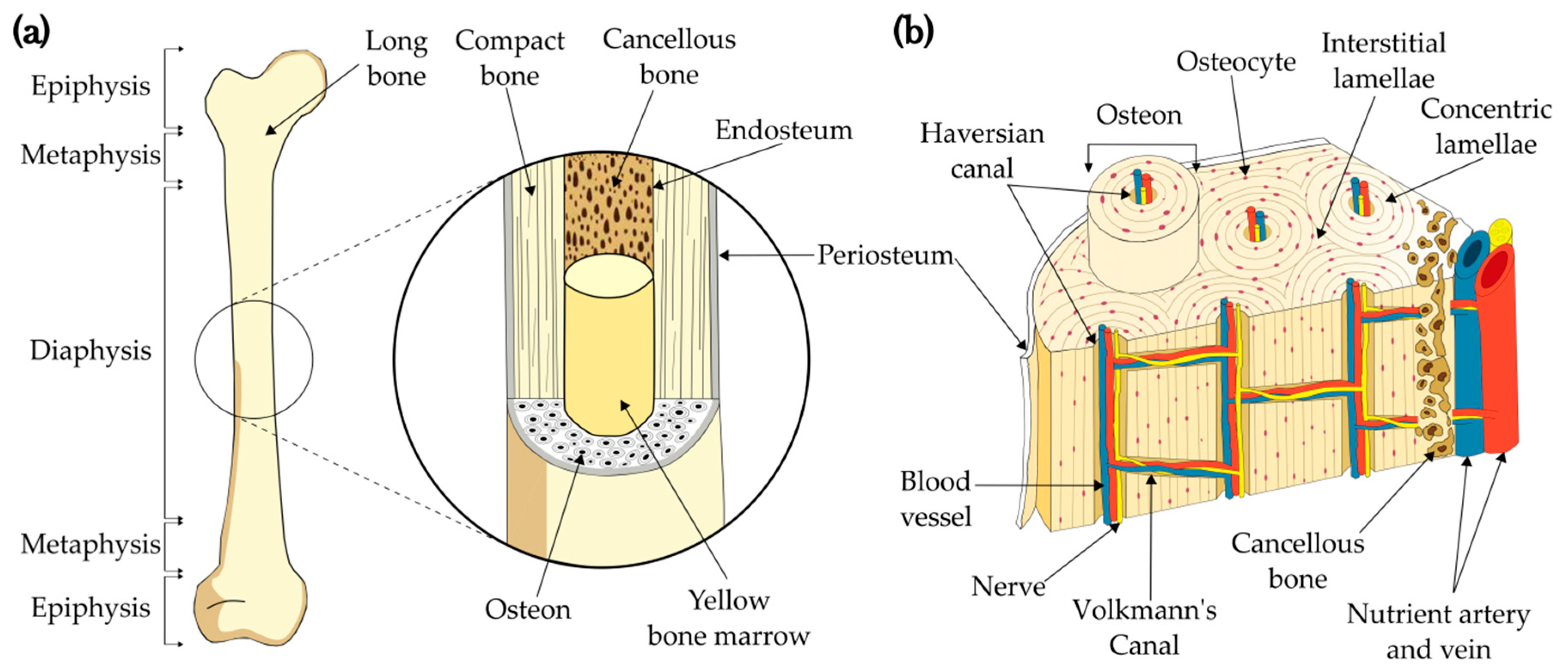
1.1. Bone structure
Cortical Bone as a Biomimetic 3D Model
2. Materials and Methods
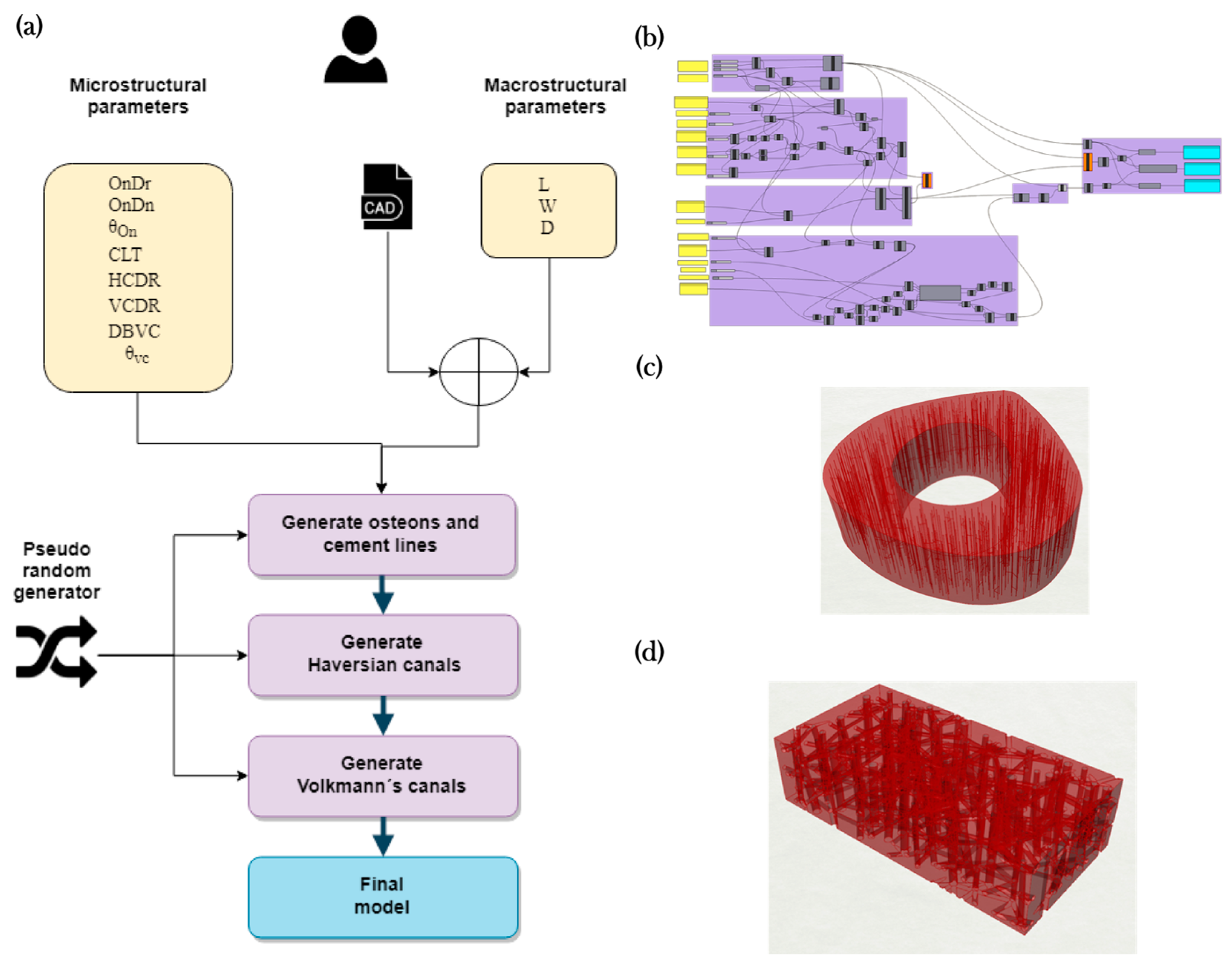
2.1. Algorithm for Generating the Cortical Bone Models
2.1.1. Modeling Algorithm
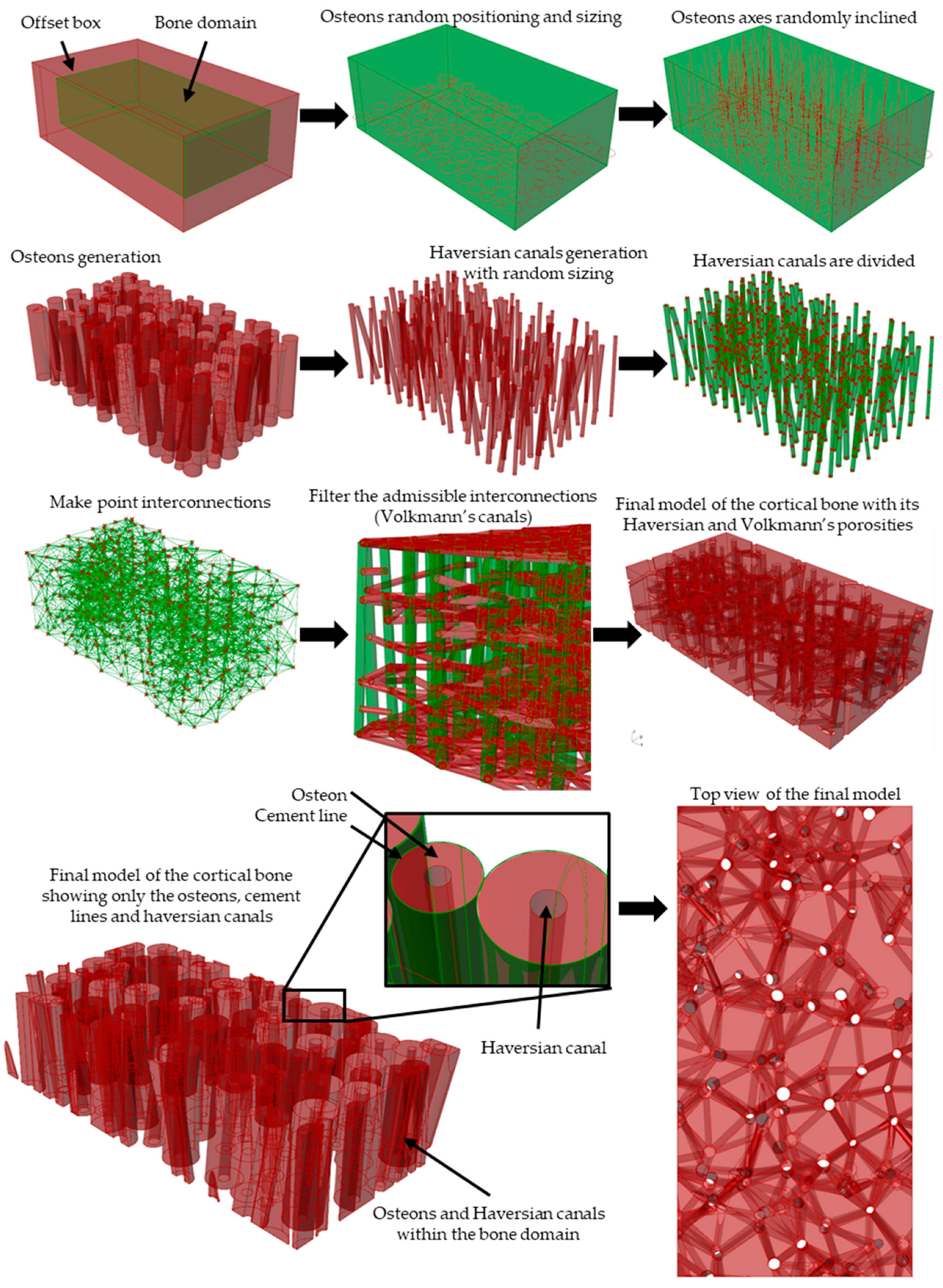
2.1.2. Modeling Algorithm Process and Steps
2.1.3. Modeling Algorithm In-Silico Validation with Porosity Check
2.2. Experimental Validation towards Scaffold Usage Employing Additive Manufacturing and XCT-Scanning
3. Results and discussion
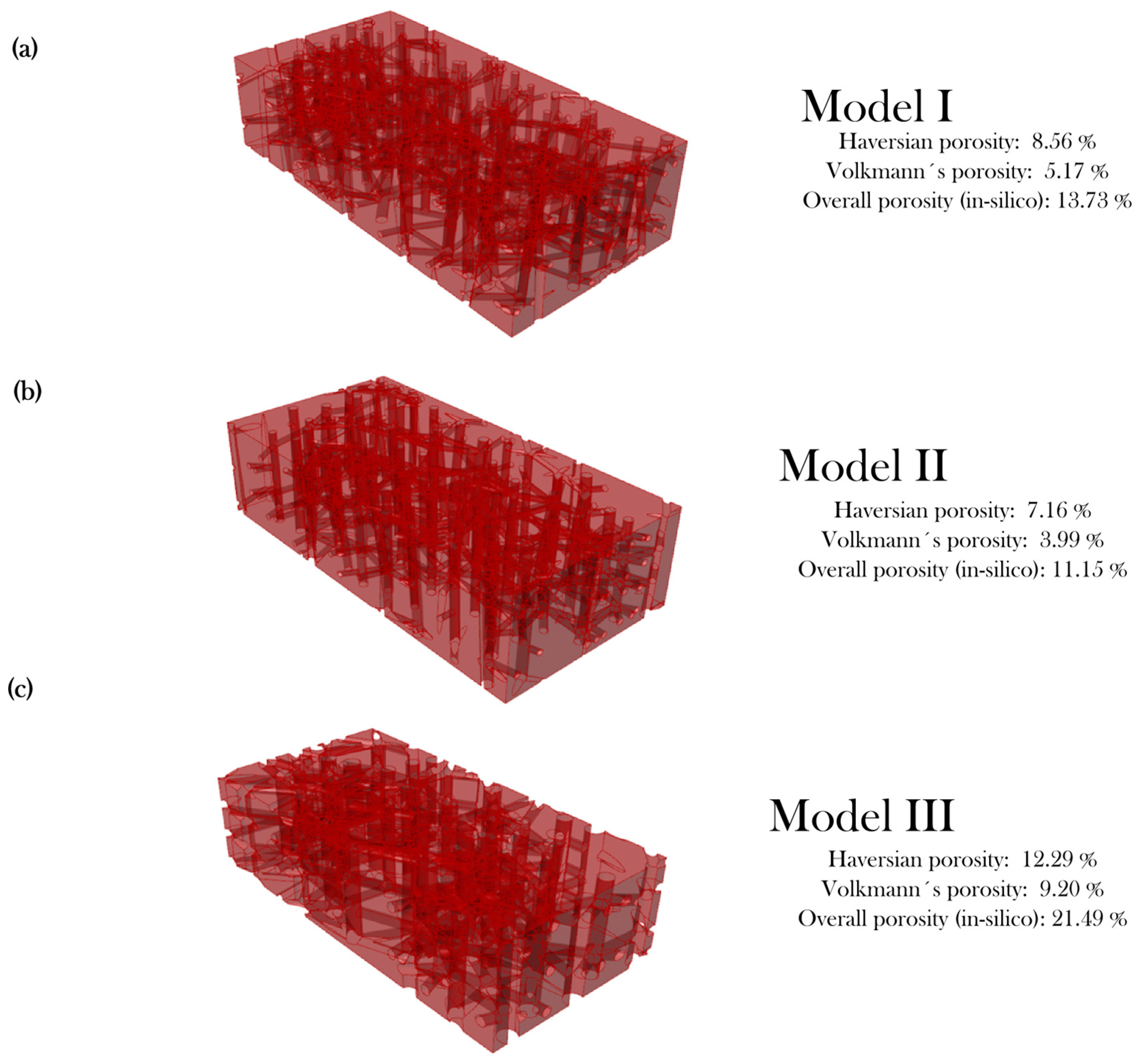
3.1. In-Silico Porosity Check
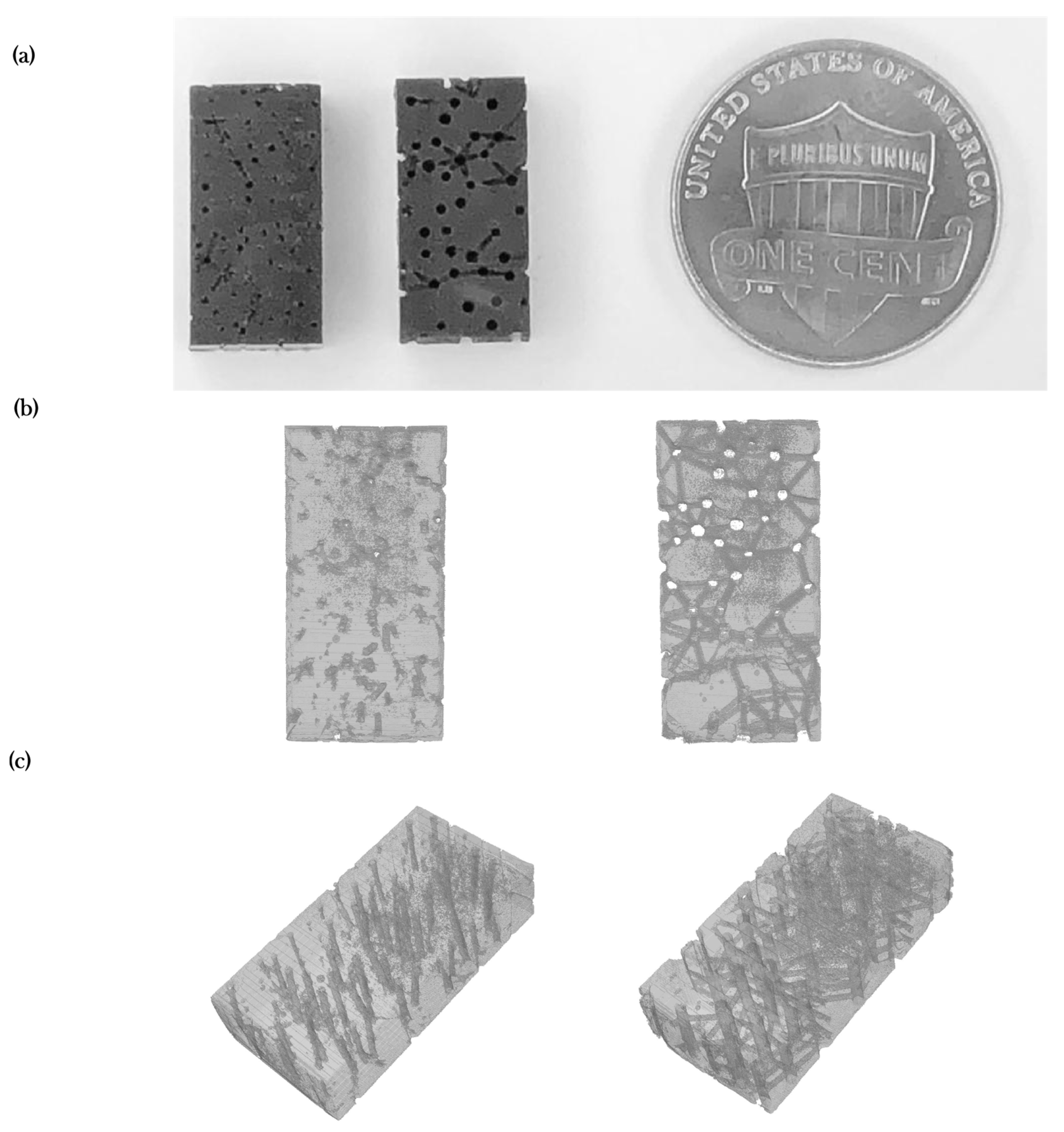
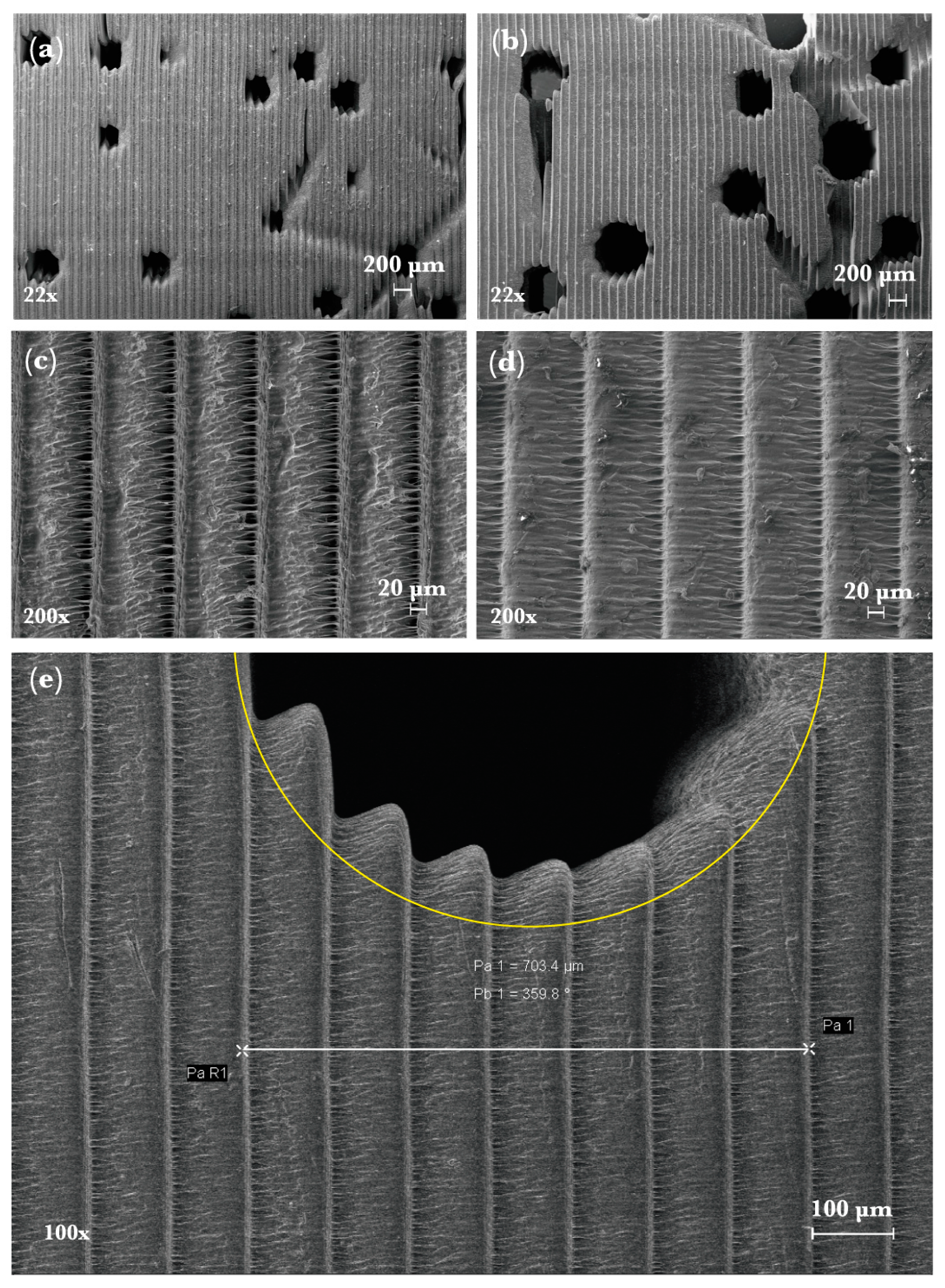
3.2. Experimental Porosity Check
4. Conclusions
- A flexible parametric algorithm for mimicking the bone microstructure in a 3D model was successfully developed and employed for the first time. This approach allows the dynamic generation of a tissue model without exposing a patient to x-ray and can be adapted to different health conditions.
- Use of bone parameters and pseudo-random numbers allows the generation of bone microstructures dynamically. It was found that the algorithm is consistent for creating bone samples within acceptable porosity levels if the provided inputs are within healthy parameters. Conversely, including parameters outside those reported for healthy tissue will generate osteoporotic bone microstructure.
- Merging of two or more osteons is a feature of the algorithm. This represents a more realistic approach of intricate hierarchical structure of bone as osteon merging is naturally occurs during the bone modeling and remodeling process.
- 3D printing microstructural porous structures towards cortical bone implant fabrication remains a challenge given the limitations of additive manufacturing of microchannels for synthetic bone graft based on polymer. Implementation of technologies as TPP could increase the chance to reproduce biomimetic models with a 1:1 scale and remains a next step for future work.
- This work is one step forward in the modeling and fabrication of cortical bone.
Author Contributions
Funding
Acknowledgments
Conflicts of Interest
References
- Wegst, U.G.K.; Bai, H.; Saiz, E.; Tomsia, A.P.; Ritchie, R.O. Bioinspired structural materials. Nat. Mater. 2015, 14, 23–36. [Google Scholar] [CrossRef] [PubMed]
- Chen, Q.; Pugno, N.M. Bio-mimetic mechanisms of natural hierarchical materials: A review. J. Mech. Behav. Biomed. Mater. 2013, 19, 3–33. [Google Scholar] [CrossRef] [PubMed]
- Zhao, Y.; Xie, Z.; Gu, H.; Zhu, C.; Gu, Z. Bio-inspired variable structural color materials. Chem. Soc. Rev. 2012, 41, 3297. [Google Scholar] [CrossRef] [PubMed]
- Autumn, K.; Sitti, M.; Liang, Y.A.; Peattie, A.M.; Hansen, W.R.; Sponberg, S.; Kenny, T.W.; Fearing, R.; Israelachvili, J.N.; Full, R.J. Evidence for van der Waals adhesion in gecko setae. Proc. Natl. Acad. Sci. USA 2002, 99, 12252–12256. [Google Scholar] [CrossRef]
- Solga, A.; Cerman, Z.; Striffler, B.F.; Spaeth, M.; Barthlott, W. The dream of staying clean: Lotus and biomimetic surfaces. Bioinspir. Biomim. 2007, 2, S126–S134. [Google Scholar] [CrossRef]
- Rodriguez, C.A.; Lara-Padilla, H.; Dean, D. Bioceramics for musculoskeletal regenerative medicine: Materials and manufacturing process compatibility for synthetic bone grafts and medical devices. In 3D Printing and Biofabrication; Ovsianikov, A., Yoo, J., Mironov, V., Eds.; Springer International Publishing: New York, NY, USA, 2018; pp. 1–33. [Google Scholar]
- Li, X.; He, J.; Zhang, W.; Jiang, N.; Li, D.; Li, X.; He, J.; Zhang, W.; Jiang, N.; Li, D. Additive manufacturing of biomedical constructs with biomimetic structural organizations. Materials 2016, 9, 909. [Google Scholar] [CrossRef]
- Singh, S.; Ramakrishna, S.; Singh, R. Material issues in additive manufacturing: A review. J. Manuf. Process. 2017, 25, 185–200. [Google Scholar] [CrossRef]
- Linares-Alvelais, J.; Figueroa-Cavazos, J.; Chuck-Hernandez, C.; Siller, H.; Rodríguez, C.; Martínez-López, J. Hydrostatic high-pressure post-processing of specimens fabricated by DLP, SLA, and FDM: An alternative for the sterilization of polymer-based biomedical devices. Materials 2018, 11, 2540. [Google Scholar] [CrossRef]
- Chen, Q.; Thouas, G.A. Metallic implant biomaterials. Mater. Sci. Eng. R Rep. 2015, 87, 1–57. [Google Scholar] [CrossRef]
- Teo, W.Z.W.; Schalock, P.C. Metal hypersensitivity reactions to orthopedic implants. Dermatol. Ther. (Heidelb.) 2017, 7, 53–64. [Google Scholar] [CrossRef]
- Rankin, T.M.; Giovinco, N.A.; Cucher, D.J.; Watts, G.; Hurwitz, B.; Armstrong, D.G. Three-dimensional printing surgical instruments: Are we there yet? J. Surg. Res. 2014, 189, 193–197. [Google Scholar] [CrossRef] [PubMed]
- Lynn, N.S.; Martínez-López, J.-I.; Bocková, M.; Adam, P.; Coello, V.; Siller, H.R.; Homola, J. Biosensing enhancement using passive mixing structures for microarray-based sensors. Biosens. Bioelectron. 2014, 54, 506–514. [Google Scholar] [CrossRef] [PubMed]
- Martínez-López, J.I.; Mojica, M.; Rodríguez, C.A.; Siller, H.R. Xurography as a rapid fabrication alternative for point-of-care devices: Assessment of passive micromixers. Sensors 2016, 16, 705. [Google Scholar] [CrossRef] [PubMed]
- Martínez-López, J.I.; Betancourt, H.A.; García-López, E.; Rodriguez, C.A.; Siller, H.R. Rapid fabrication of disposable micromixing arrays using xurography and laser ablation. Micromachines 2017, 8, 144. [Google Scholar] [CrossRef]
- Santiuste, C.; Rodríguez-Millán, M.; Giner, E.; Miguélez, H. The influence of anisotropy in numerical modeling of orthogonal cutting of cortical bone. Compos. Struct. 2014, 116, 423–431. [Google Scholar] [CrossRef]
- Conward, M.; Samuel, J. Machining characteristics of the haversian and plexiform components of bovine cortical bone. J. Mech. Behav. Biomed. Mater. 2016, 60, 525–534. [Google Scholar] [CrossRef]
- Zhang, C.; Mcadams, D.A.; Grunlan, J.C. Nano/Micro-manufacturing of bioinspired materials: A review of methods to mimic natural structures. Adv. Mater. 2016, 28, 6292–6321. [Google Scholar] [CrossRef]
- Tran, P.; Ngo, T.D.; Ghazlan, A.; Hui, D. Bimaterial 3D printing and numerical analysis of bio-inspired composite structures under in-plane and transverse loadings. Compos. Part B Eng. 2017, 108, 210–223. [Google Scholar] [CrossRef]
- Duro-Royo, J.; Zolotovsky, K.; Mogas-Soldevila, L.; Varshney, S.; Boyce, M.C. MetaMesh: A hierarchical computational model for design and fabrication of biomimetic armored surfaces. Comput. Des. 2015, 60, 14–27. [Google Scholar] [CrossRef]
- Crowley, C.; Wong, J.M.; Fisher, D.M.; Khan, W.S. A Systematic review on preclinical and clinical studies on the use of scaffolds for bone repair in skeletal defects. Curr. Stem Cell Res. Ther. 2013, 8, 243–252. [Google Scholar] [CrossRef]
- Predoi-Racila, M.; Crolet, J.M. Human cortical bone: the SiNuPrOs model. Comput. Methods Biomech. Biomed. Engin. 2008, 11, 169–187. [Google Scholar] [CrossRef] [PubMed]
- Cowin, S.C.; Cardoso, L. Blood and interstitial flow in the hierarchical pore space architecture of bone tissue. J. Biomech. 2015, 48, 842–854. [Google Scholar] [CrossRef]
- Yeni, Y.N.; Brown, C.U.; Wang, Z.; Norman, T.L. The influence of bone morphology on fracture toughness of the human femur and tibia. Bone 1997, 21, 453–459. [Google Scholar] [CrossRef]
- Mirzaali, M.J.; Schwiedrzik, J.J.; Thaiwichai, S.; Best, J.P.; Michler, J.; Zysset, P.K.; Wolfram, U. Mechanical properties of cortical bone and their relationships with age, gender, composition and microindentation properties in the elderly. Bone 2016, 93, 196–211. [Google Scholar] [CrossRef] [PubMed]
- Vergani, L.; Colombo, C.; Libonati, F. Crack propagation in cortical bone: A numerical study. Procedia Mater. Sci. 2014, 3, 1524–1529. [Google Scholar] [CrossRef]
- Wang, M.; Zimmermann, E.A.; Riedel, C.; Busseb, B.; Li, S.; Silberschmidt, V.V. Effect of micro-morphology of cortical bone tissue on fracture toughness and crack propagation. Procedia Struct. Integr. 2017, 6, 64–68. [Google Scholar] [CrossRef]
- Nguyen, V.H.; Lemaire, T.; Naili, S. Poroelastic behaviour of cortical bone under harmonic axial loading: A finite element study at the osteonal scale. Med. Eng. Phys. 2010, 32, 384–389. [Google Scholar] [CrossRef]
- Demirtas, A.; Curran, E.; Ural, A. Assessment of the effect of reduced compositional heterogeneity on fracture resistance of human cortical bone using finite element modeling. Bone 2016, 91, 92–101. [Google Scholar] [CrossRef]
- Wang, Y.; Ural, A. Mineralized collagen fibril network spatial arrangement influences cortical bone fracture behavior. J. Biomech. 2017, 66, 70–77. [Google Scholar] [CrossRef]
- Khor, F.; Cronin, D.S.; Watson, B.; Gierczycka, D.; Malcolm, S. Importance of asymmetry and anisotropy in predicting cortical bone response and fracture using human body model femur in three-point bending and axial rotation. J. Mech. Behav. Biomed. Mater. 2018, 87, 213–229. [Google Scholar] [CrossRef]
- Predoi-Racila, M.; Stroe, M.C.; Crolet, J.M. Human cortical bone: The SiNuPrOs model. Part II—A multi-scale study of permeability. Comput. Methods Biomech. Biomed. Eng. 2010, 13, 81–89. [Google Scholar] [CrossRef]
- Wu, J.; Aage, N.; Westermann, R.; Sigmund, O. Infill optimization for additive manufacturing-approaching bone-like porous structures. IEEE Trans. Vis. Comput. Graph. 2018, 24, 1127–1140. [Google Scholar] [CrossRef]
- Gregor, A.; Filová, E.; Novák, M.; Kronek, J.; Chlup, H.; Buzgo, M.; Blahnová, V.; Lukášová, V.; Bartoš, M.; Nečas, A.; et al. Designing of PLA scaffolds for bone tissue replacement fabricated by ordinary commercial 3D printer. J. Biol. Eng. 2017, 11, 31. [Google Scholar] [CrossRef] [PubMed]
- Rubenstein, D.A.; Yin, W.; Frame, M.D. Biofluid Mechanics: An Introduction to Fluid Mechanics, Macrocirculation, and Microcirculation; Elsevier Inc.: Amsterdam, The Netherlands, 2016; ISBN 9780128009444. [Google Scholar]
- Dzwierzynska, J.; Prokopska, A.; Dzwierzynska, J.; Prokopska, A. Pre-rationalized parametric designing of roof shells formed by repetitive modules of catalan surfaces. Symmetry 2018, 10, 105. [Google Scholar] [CrossRef]
- Hsu, M.-C.; Kamensky, D.; Xu, F.; Kiendl, J.; Wang, C.; Wu, M.C.H.; Mineroff, J.; Reali, A.; Bazilevs, Y.; Sacks, M.S. Dynamic and fluid-structure interaction simulations of bioprosthetic heart valves using parametric design with T-splines and Fung-type material models. Comput. Mech. 2015, 55, 1211–1225. [Google Scholar] [CrossRef] [PubMed]
- Low, Z.-X.; Chua, Y.T.; Ray, B.M.; Mattia, D.; Metcalfe, I.S.; Patterson, D.A. Perspective on 3D printing of separation membranes and comparison to related unconventional fabrication techniques. J. Memb. Sci. 2017, 523, 596–613. [Google Scholar] [CrossRef]
- Takada, K.; Sun, H.-B.; Kawata, S. Improved spatial resolution and surface roughness in photopolymerization-based laser nanowriting. Appl. Phys. Lett. 2005, 86, 071122. [Google Scholar] [CrossRef]
- 3D printing on the micrometer scale - Nanoscribe GmbH. Available online: https://www.nanoscribe.de/en/ (accessed on 11 March 2019).
- Schmidleithner, C.; Kalaskar, D.M. Stereolithography. In 3D Printing; Cvetkovic, D., Ed.; InTech: London, UK, 2018. [Google Scholar]
- Stansbury, J.W.; Idacavage, M.J. 3D printing with polymers: Challenges among expanding options and opportunities. Dental Mater. 2016, 32, 54–64. [Google Scholar] [CrossRef] [PubMed]
- Salmoria, G.V.; Ahrens, C.H.; Beal, V.E.; Pires, A.T.N.; Soldi, V. Evaluation of post-curing and laser manufacturing parameters on the properties of SOMOS 7110 photosensitive resin used in stereolithography. Mater. Des. 2009, 30, 758–763. [Google Scholar] [CrossRef]


| Work | * Ref | Integrity | Volkmann System | Haversian System | Source | Dimension |
|---|---|---|---|---|---|---|
| Vergani et al. | [26] | Partial | NA ** | Yes | Literature | 2D |
| Wang et al. | [27] | Full | NA | Yes | Specimen | 2D |
| Nguyen et al. | [28] | Partial | NA | Yes | Literature | 2D |
| Demirtas et al. | [29] | Full | NA | Yes | Specimen | 3D |
| Wang et al. | [30] | Partial | NA | NA | Literature | 3D |
| Khor et al. | [31] | Full | NA | NA | Specimen | 3D |
| Predoi-Racila et Crolet | [32] | Full | Yes | Yes | Literature | 3D |
| Wu et al. | [33] | NA | NA | NA | Mathematical | 3D |
| Gregor et al. | [34] | Full | NA | NA | Mathematical | 3D |
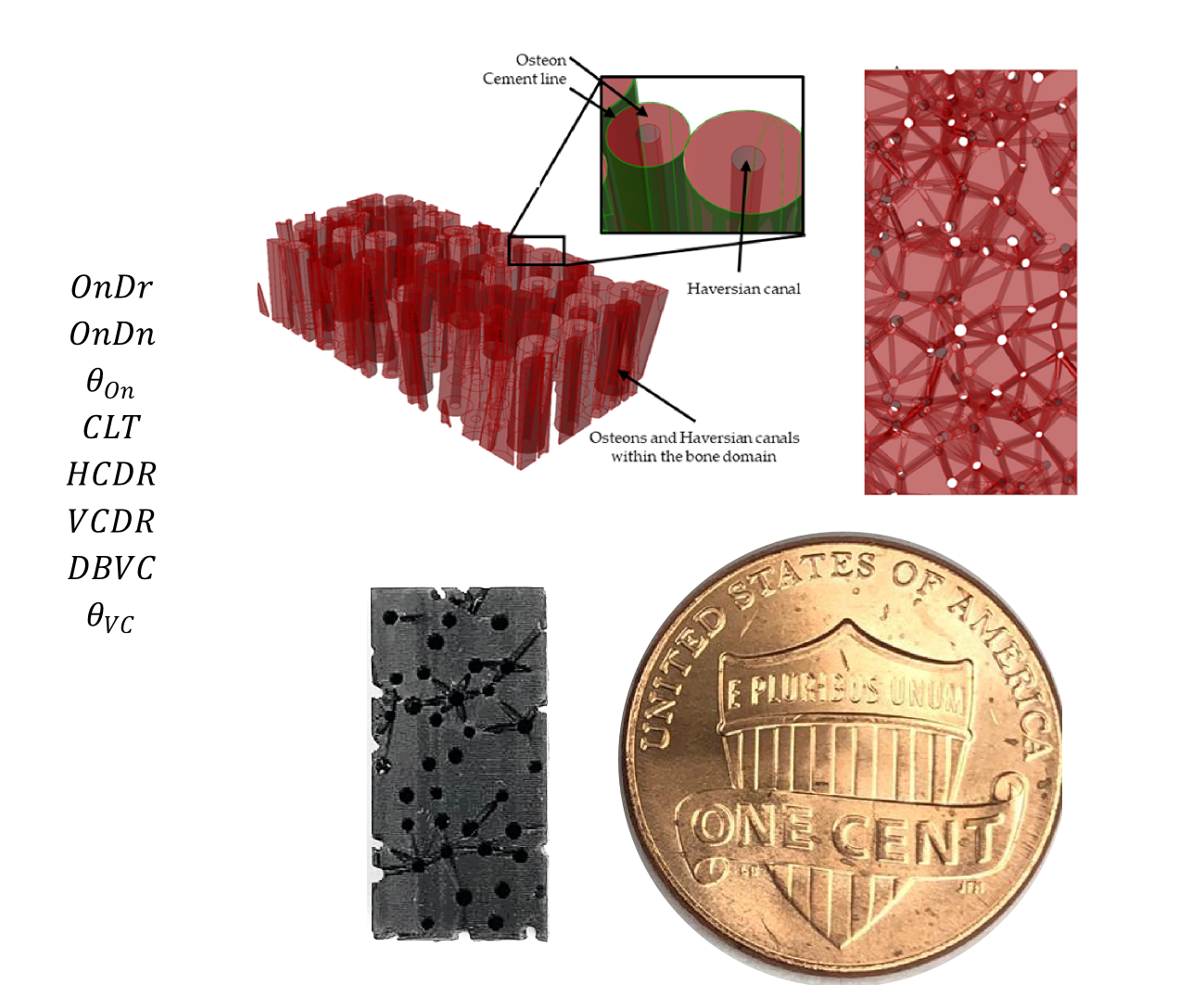
| Parameter | Type | Description | Admissible Values |
|---|---|---|---|
| Input | Osteon diameter range | 100 to 250 μm [3,4] | |
| Input | Osteon density | 10 to 25 Osteons/mm2 [24] | |
| Input | Osteon inclination angle range | 0° to 15° [23] | |
| Input | Cement line thickness range | 0 to 5 μm [22] | |
| Input | Haversian canals diameter range | 40 to 90 μm [22] | |
| Input | Volkmann’s canals diameter range | 40 to 50 μm [22] | |
| Input | Distance between Volkmann’s canals | 150 to 500 μm [22] | |
| Input | Maximum inclination angle of the Volkmann’s canals | 15° [23] | |
| – | Output | Haversian porosity | 6 ± 3% [22] |
| – | Output | Volkmann´s porosity | 8 ± 3% [22] |
| – | Output | Overall porosity | 14 ±6% [22] |
| Input Variable | Model I – Healthy | Model II – Healthy | Model III – Osteoporotic |
|---|---|---|---|
| (μm) | 100–250 | 120–240 | 180–250 |
| (Ons/mm2) | 22 | 18.5 | 9.5 |
| (°) | 0–10 | 0–6.5 | 0–3 |
| (μm) | 0–5 | 1–4 | 0–3 |
| (μm) | 50–90 | 60–85 | 95–150 |
| (μm) | 40–50 | 45–50 | 70–80 |
| (μm) | 150–500 | 150–400 | 165–400 |
| (°) | 15 | 13 | 15 |
| Model | Literature | In-silico | Experimental (Cured) | Threshold Deviation 1 |
|---|---|---|---|---|
| I—Healthy | 14 ± 6% [22] | 13.73% | 5.79 ± 0.64% | −2.21% |
| III—Osteoporosis | >20% [22] | 21.49% | 16.16 ± 1.02% | −3.84% |
© 2019 by the authors. Licensee MDPI, Basel, Switzerland. This article is an open access article distributed under the terms and conditions of the Creative Commons Attribution (CC BY) license (http://creativecommons.org/licenses/by/4.0/).
Share and Cite
Robles-Linares, J.A.; Ramírez-Cedillo, E.; Siller, H.R.; Rodríguez, C.A.; Martínez-López, J.I. Parametric Modeling of Biomimetic Cortical Bone Microstructure for Additive Manufacturing. Materials 2019, 12, 913. https://doi.org/10.3390/ma12060913
Robles-Linares JA, Ramírez-Cedillo E, Siller HR, Rodríguez CA, Martínez-López JI. Parametric Modeling of Biomimetic Cortical Bone Microstructure for Additive Manufacturing. Materials. 2019; 12(6):913. https://doi.org/10.3390/ma12060913
Chicago/Turabian StyleRobles-Linares, José A., Erick Ramírez-Cedillo, Hector R. Siller, Ciro A. Rodríguez, and J. Israel Martínez-López. 2019. "Parametric Modeling of Biomimetic Cortical Bone Microstructure for Additive Manufacturing" Materials 12, no. 6: 913. https://doi.org/10.3390/ma12060913
APA StyleRobles-Linares, J. A., Ramírez-Cedillo, E., Siller, H. R., Rodríguez, C. A., & Martínez-López, J. I. (2019). Parametric Modeling of Biomimetic Cortical Bone Microstructure for Additive Manufacturing. Materials, 12(6), 913. https://doi.org/10.3390/ma12060913