FEM Analysis of Dental Implant-Abutment Interface Overdenture Components and Parametric Evaluation of Equator® and Locator® Prosthodontics Attachments


Abstract
1. Introduction
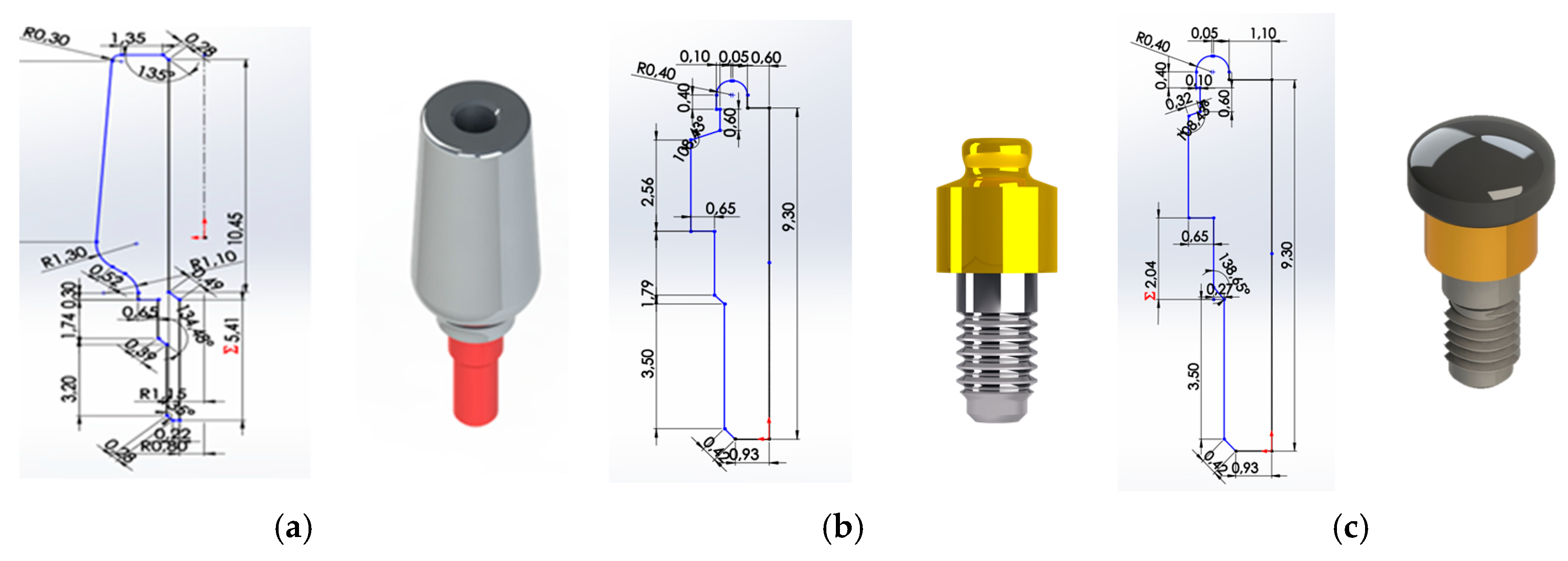
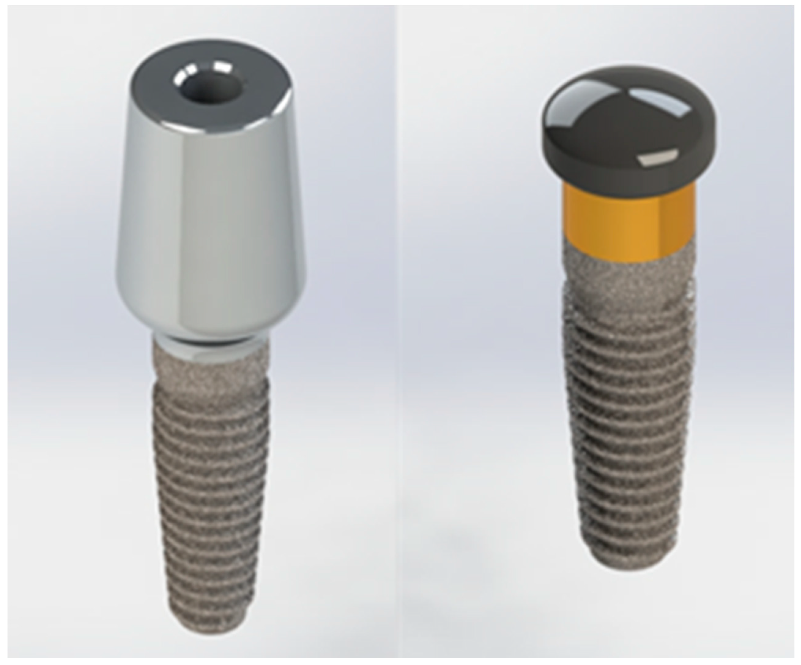
- (1)
- UNIVERSAL ABUTMENT,
- (2)
- LOCATOR® ABUTMENT,
- (3)
- EQUATOR® ABUTMENT.
2. Materials and Methods
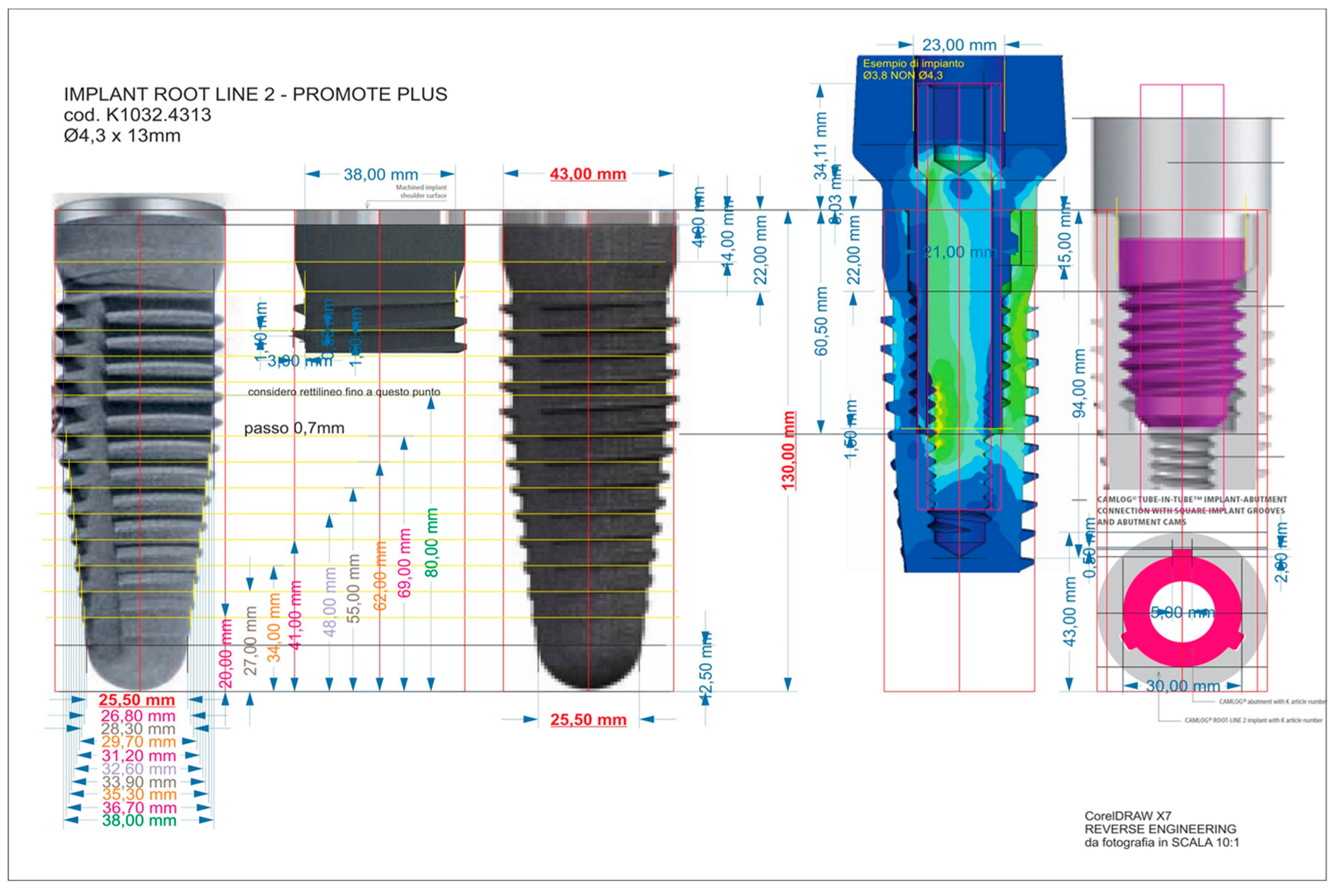
2.1. Reverse Engineering
2.2. Finite Element Analysis
2.2.1. Mechanical Characteristic of the Materials
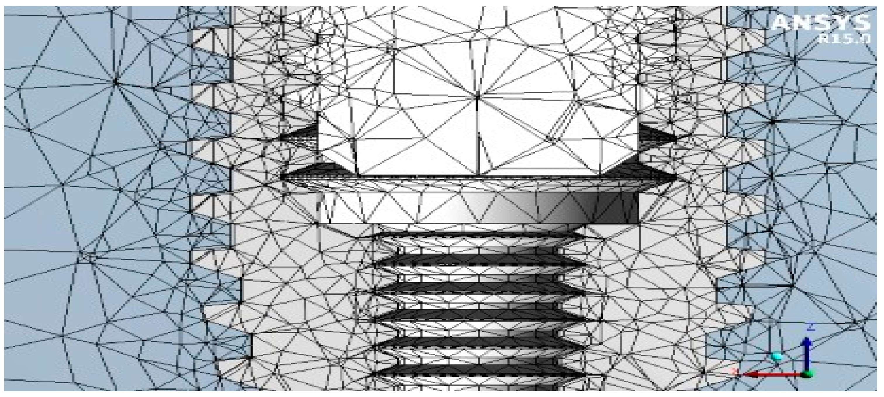
2.2.2. Mesh
2.2.3. Boundary Conditions
- implant/bone;P [N] = M/(0.2 D) = 40 N;
- lacator abutment;P [N] = M/(0.2 D) = 50 N;
- equator abutment;P [N] = M/(0.2 D) = 50 N;
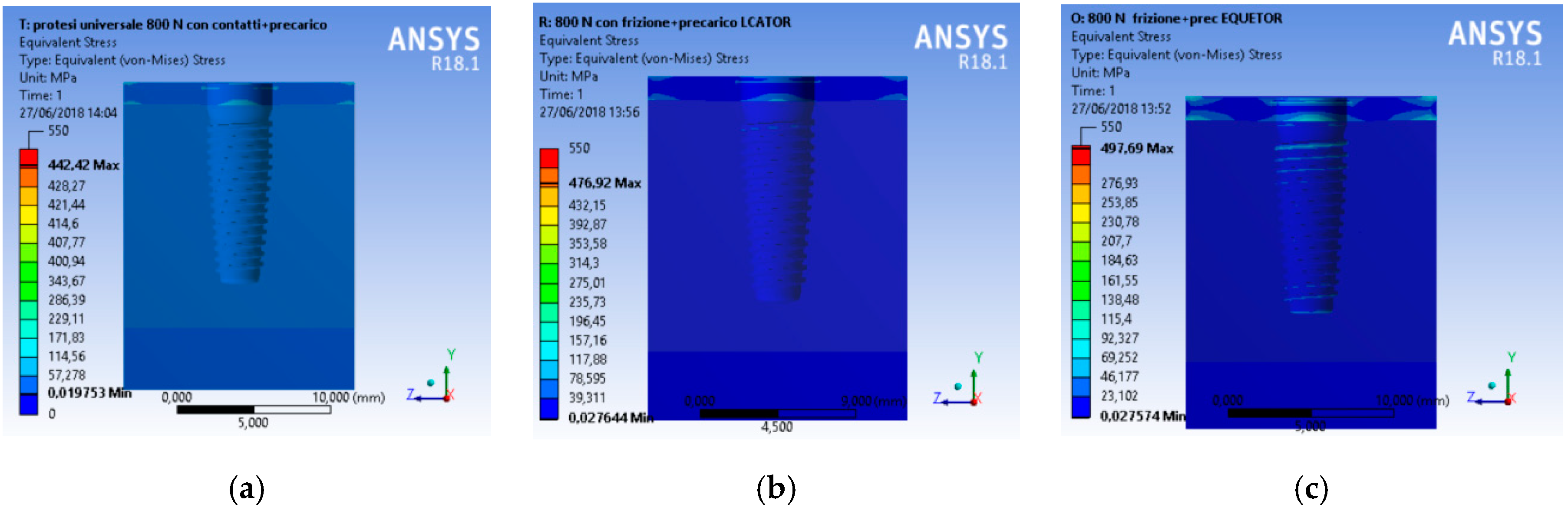
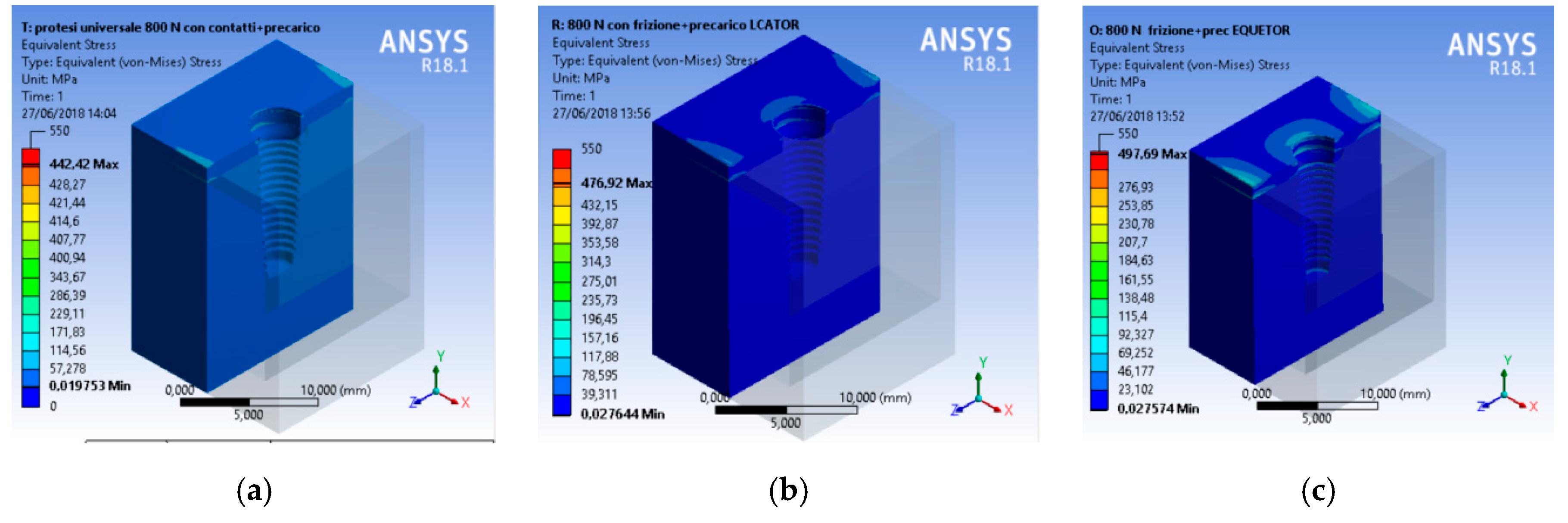
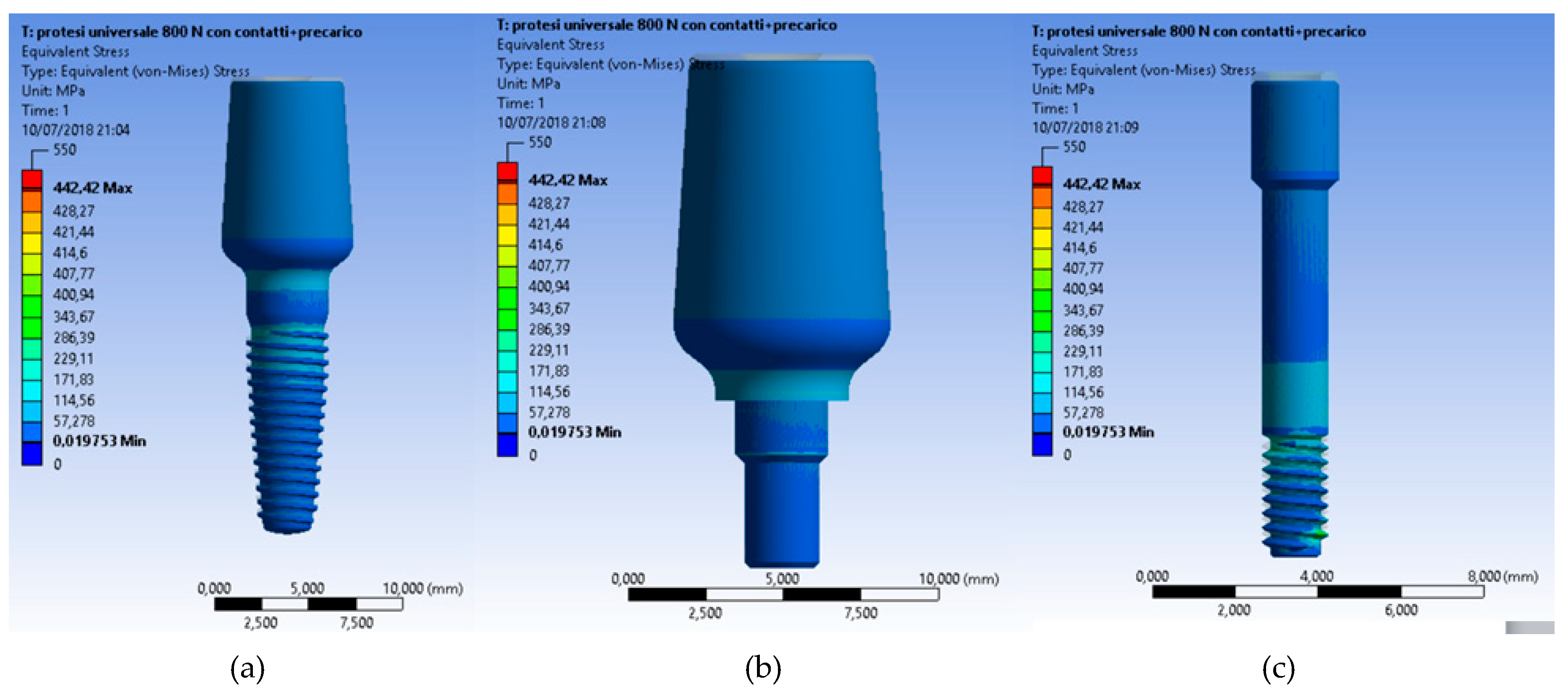
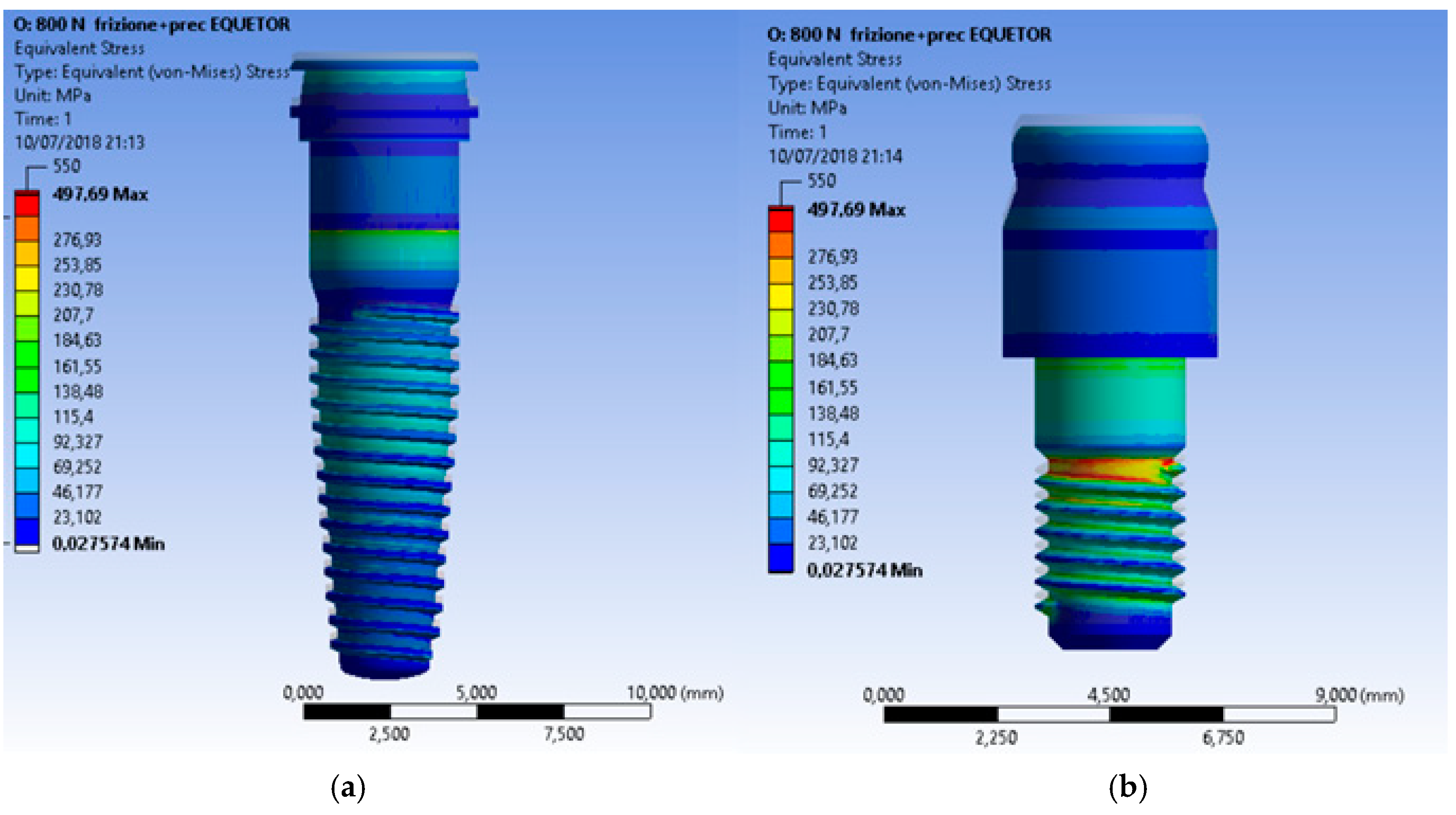
3. Results and Discussion
4. Conclusions
Author Contributions
Funding
Acknowledgments
Conflicts of Interest
References
- von Meyer, H. Die architectur der spongiosa. Archiv fur Anatomie und Physiologie 1867, 47, 615–628. [Google Scholar]
- Cawood, J.I.; Howell, R.A. Reconstructive preprosthetic surgery. I. Anatomical considerations. Int. J. Oral Maxillofac. Surg. 1991, 20, 75–82. [Google Scholar] [CrossRef]
- Cervino, G.; Romeo, U.; Lauritano, F.; Bramanti, E.; Fiorillo, L.; D’Amico, C.; Milone, D.; Laino, L.; Campolongo, F.; Rapisarda, S.; et al. Fem and Von Mises Analysis of OSSTEM® Dental Implant Structural Components: Evaluation of Different Direction Dynamic Loads. Open Dent. J. 2018, 12, 219–229. [Google Scholar] [CrossRef] [PubMed]
- Cicciù, M.; Risitano, G.; Maiorana, C.; Franceschini, G. Parametric analysis of the strength in the “Toronto” osseous-prosthesis system. Minerva Stomatol. 2009, 58, 9–23. [Google Scholar] [PubMed]
- Cicciu, M.; Bramanti, E.; Matacena, G.; Guglielmino, E.; Risitano, G. FEM evaluation of cemented-retained versus screw-retained dental implant single-tooth crown prosthesis. Int. J. Clin. Exp. Med. 2014, 7, 817–825. [Google Scholar] [PubMed]
- Bramanti, E.; Cervino, G.; Lauritano, F.; Fiorillo, L.; D’Amico, C.; Sambataro, S.; Denaro, D.; Famà, F.; Ierardo, G.; Polimeni, A.; et al. FEM and von mises analysis on prosthetic crowns structural elements: Evaluation of different applied materials. Sci. World J. 2017. [Google Scholar] [CrossRef] [PubMed]
- Lauritano, F.; Runci, M.; Cervino, G.; Fiorillo, L.; Bramanti, E.; Cicciù, M. Three-dimensional evaluation of different prosthesis retention systems using finite element analysis and the Von Mises stress test. Minerva Stomatol. 2016, 65, 353–367. [Google Scholar]
- Cicciù, M.; Cervino, G.; Bramanti, E.; Lauritano, F.; Lo Gudice, G.; Scappaticci, L.; Rapparini, A.; Guglielmino, E.; Risitano, G. FEM analysis of mandibular prosthetic overdenture supported by dental implants: Evaluation of different retention methods. Comput. Math. Methods Med. 2015, 2015, 943839. [Google Scholar] [CrossRef]
- Zarone, F.; Apicella, A.; Nicolais, L.; Aversa, R.; Sorrentino, R. Mandibular flexure and stress build-up in mandibular full-arch fixed prostheses supported by osseointegrated implants. Clin. Oral Implants Res. 2003, 14, 103–114. [Google Scholar] [CrossRef]
- Cicciù, M.; Cervino, G.; Milone, D.; Risitano, G. FEM Investigation of the Stress Distribution over Mandibular Bone Due to Screwed Overdenture Positioned on Dental Implants. Materials 2018, 11, 1512. [Google Scholar] [CrossRef]
- Albrektsson, T.; Zarb, G.; Worthington, P.; Eriksson, A.R. The long-term efficacy of currently used dental implants: A review and proposed criteria of success. Int. J. Oral Maxillofac. Implants 1986, 1, 11–25. [Google Scholar] [PubMed]
- Rasmussen, E.J. Alternative prosthodontic technique for tissue-integrated prostheses. J. Prosthet. Dent. 1987, 57, 198–204. [Google Scholar] [CrossRef]
- Alexandridis, C.; Caputo, A.A.; Thanos, C.E. Distribution of stresses in the human skull. J. Oral Rehabil. 1985, 12, 499–507. [Google Scholar] [CrossRef]
- Rangert, B.; Jemt, T.; Jorneus, L. Forces and moments on branemark implants. Int. J. Oral Maxillofac. Implants 1989, 4, 241–247. [Google Scholar] [PubMed]
- Pruim, G.J.; de Jongh, H.J.; ten Bosch, J.J. Forces acting on the mandible during bilateral static bite at different bite force levels. J. Biomech. 1980, 13, 755–763. [Google Scholar] [CrossRef]
- Di Salle, A.; Spagnuolo, G.; Conte, R.; Procino, A.; Peluso, G.; Rengo, C. Effects of various prophylactic procedures on titanium surfaces and biofilm formation. J. Period. Implant Sci. 2018, 48, 373–382. [Google Scholar] [CrossRef]
- Cicciù, M.; Bramanti, E.; Cecchetti, F.; Scappaticci, L.; Guglielmino, E.; Risitano, G. FEM and Von Mises analyses of different dental implant shapes for masticatory loading distribution. ORAL Implantol. 2014, 7, 1–10. [Google Scholar]
- De Vico, G.; Bonino, M.; Spinelli, D.; Schiavetti, R.; Sannino, G.; Pozzi, A.; Ottria, L. Rationale for tilted implants: FEA considerations and clinical reports. ORAL Implantol. 2012, 4, 23–33. [Google Scholar]
- Vayron, R.; Nguyen, V.-H.; Lecuelle, B.; Albini Lomami, H.; Meningaud, J.-P.; Bosc, R.; Haiat, G. Comparison of Resonance Frequency Analysis and of Quantitative Ultrasound to Assess Dental Implant Osseointegration. Sensors 2018, 18, 1397. [Google Scholar] [CrossRef]
- Mailath, G.; Stoiber, B.; Watzek, G.; Matejka, M. bone resorption at the entry of osseointegrated implants—A biomechanical phenomenon. Finite element study. Z. Stomatol. 1989, 86, 207–216. [Google Scholar]
- Haack, J.E.; Sakaguchi, R.L.; Sun, T.; Coffey, J.P. Elongation and preload stress in dental implant abutment screws. Int. J. Oral Maxillofac. Implants 1995, 10, 529–536. [Google Scholar] [PubMed]
- Versluis, A.; Korioth, T.W.; Cardoso, A.C. Numerical analysis of a dental implant system preloaded with a washer. Int. J. Oral Maxillofac. Implants 1999, 14, 337–341. [Google Scholar] [PubMed]
- van Steenberghe, D.; Lekholm, U.; Bolender, C.; Folmer, T.; Henry, P.; Herrmann, I.; Higuchi, K.; Laney, W.; Linden, U.; Astrand, P. Applicability of osseointegrated oral implants in the rehabilitation of partial edentulism: A prospective multicenter study on 558 fixtures. Int. J. Oral Maxillofac. Implants 1990, 5, 272–281. [Google Scholar] [PubMed]
- Esposito, M.; Hirsch, J.M.; Lekholm, U.; Thomsen, P. Biological factors contributing to failures of osseointegrated oral implants. (ii). Etiopathogenesis. Eur. J. Oral Sci. 1998, 106, 721–764. [Google Scholar] [CrossRef] [PubMed]
- Meijer, H.J.; Starmans, F.J.; Steen, W.H.; Bosman, F. Location of implants in the interforaminal region of the mandible and the consequences for the design of the superstructure. J. Oral Rehabil. 1994, 21, 47–56. [Google Scholar] [CrossRef] [PubMed]
- Meijer, G.J.; Starmans, F.J.; de Putter, C.; van Blitterswijk, C.A. The influence of a flexible coating on the bone stress around dental implants. J. Oral Rehabil. 1995, 22, 105–111. [Google Scholar] [CrossRef] [PubMed]
- Clift, S.E.; Fisher, J.; Watson, C.J. Finite element stress and strain analysis of the bone surrounding a dental implant: Effect of variations in bone modulus. Proc. Inst. Mech. Eng. H 1992, 206, 233–241. [Google Scholar] [CrossRef]
- Young, P.G.; Beresford-West, T.B.; Coward, S.R.; Notarberardino, B.; Walker, B.; Abdul-Aziz, A. An efficient approach to converting three-dimensional image data into highly accurate computational models. Philos. Trans. A Math. Phys. Eng. Sci. 2008, 366, 3155–3173. [Google Scholar] [CrossRef]
- Lin, C.L.; Chang, S.H.; Chang, W.J.; Kuo, Y.C. Factorial analysis of variables influencing mechanical characteristics of a single tooth implant placed in the maxilla using finite element analysis and the statistics-based Taguchi method. Eur. J. Oral Sci. 2007, 115, 408–416. [Google Scholar] [CrossRef]
- Lakes, R.S.; Katz, J.L.; Sternstein, S.S. Viscoelastic properties of wet cortical bone–I. Torsional and biaxial studies. J. Biomech. 1979, 12, 657–678. [Google Scholar] [CrossRef]
- Lakes, R.S.; Katz, J.L. Viscoelastic properties of wet cortical bone–II. Relaxation mechanisms. J. Biomech. 1979, 12, 679–687. [Google Scholar] [CrossRef]
- Brown, C.U.; Norman, T.L.; Kish, V.L.; Gruen, T.A.; Blaha, J.D. Timedependent circumferential deformation of cortical bone upon internal radial loading. J. Biomech. Eng. 2002, 124, 456–461. [Google Scholar] [CrossRef] [PubMed]
- Shultz, T.R.; Blaha, J.D.; Gruen, T.A.; Norman, T.L. Cortical bone viscoelasticity and fixation strength of press-fit femoral stems: Finite element model. J. Biomech. Eng. 2006, 128, 7–12. [Google Scholar] [CrossRef] [PubMed]
- Al-Ghafli, S.A.; Michalakis, K.X.; Hirayama, H.; Kang, K. The in vitro effect of different implant angulations and cyclic dislodgement on the retentive properties of an overdenture attachment system. J. Prosthet. Dent. 2009, 102, 140–147. [Google Scholar] [CrossRef]
- Yang, T.C.; Maeda, Y.; Gonda, T.; Kotecha, S. Attachment systems for implant overdenture: Influence of implant inclination on retentive and lateral forces. Clin. Oral Implants Res. 2011, 22, 1315–1319. [Google Scholar] [CrossRef]
- Wolf, K.; Ludwig, K.; Hartfil, H.; Kern, M. Analysis of retention and wear of ball attachments. Quintessence Int. 2009, 40, 405–412. [Google Scholar]
- Cakare, R.S.; Can, T.; Yaltirik, M.; Keskin, C. Complications associated with the ball, bar and Locator attachments for implant-supported overdentures. Med. Oral Patol. Oral Cir. Bucal. 2011, 16, 953–959. [Google Scholar] [CrossRef]
- Takeshita, S.; Kanazawa, M.; Minakuchi, S. Stress analysis of mandibular two-implant overdenture with different attachment systems. Dent. Mater. J. 2011, 30, 928–934. [Google Scholar] [CrossRef]
- Keshk, A.M.; Alqutaibi, A.Y.; Algabri, R.S.; Swedan, M.S.; Kaddah, A. Prosthodontic maintenance and peri-implant tissue conditions for telescopic attachment-retained mandibular implant overdenture: Systematic review and meta-analysis of randomized clinical trials. Eur. J. Dent. 2017, 11, 559–568. [Google Scholar] [CrossRef]


| Resolution | 640 × 480 pixel |
| Zoom | 5× |
| Color | Black |
| Software | Windows 2000/2003/XP/Vista/Linux/10 |
| Dsp | 24 bit |
| Software bit | Usb 2.0–Usb 1.1 |
| Model | Usb |
| Material C | Cortical Bone | Cancellous Bone | Ti6Al4V |
|---|---|---|---|
| Density | 1.8 g/cm3 | 1.2 g/cm3 | 4.510 g/cm3 |
| Exx | 9.60 GPa | 0.144 GPa | 105 GPa |
| Eyy | 9.60 GPa | 0.099 GPa | 105 GPa |
| Ezz | 17.8 GPa | 0.344 GPa | 105 GPa |
| νxy | 0.55 | 0.23 | 0.37 |
| νyz | 0.30 | 0.11 | 0.37 |
| νxz | 0.30 | 0.13 | 0.37 |
| Gxy | 3.10 GPa | 0.053 GPa | 38.32 GPa |
| Gyz | 3.51 GPa | 0.063 GPa | 38.32 GPa |
| Gxz | 3.51 GPa | 0.045 GPa | 38.32 GPa |
| UNIVERSAL | LOCATOR | EQUATOR | |
|---|---|---|---|
| Nodes | 902,969 | 878,286 | 899,799 |
| Elements | 234,022 | 230,457 | 236,527 |
| Equator Abutment | |||
| Target Bodies | Contact Bodies | BONDED | FRECTIONAL |
| external retention matrix | inner sheath | // | |
| inner sheath | abutment | // | |
| implant | abutment | 0.3 K | |
| implant | cortical bone | 0.2 K | |
| cortical bone | cancellous bone | // | |
| implant | cancellous bone | 0.2 K | |
| Locator Abutment | |||
| Target Bodies | Contact Bodies | BONDED | FRECTIONAL |
| retention insert | abutment | // | |
| implant | abutment | 0.3 K | |
| implant | cortical bone | 0.2 K | |
| cortical bone | cancellous bone | // | |
| implant | cancellous bone | 0.2 K | |
| Universal Abutment | |||
| Target Bodies | Contact Bodies | BONDED | FRECTIONAL |
| abutment | screw | 0.3 K | |
| implant | screw | 0.3 K | |
| implant | abutment | 0.3 K | |
| implant | cortical bone | 0.2 K | |
| cortical bone | cancellous bone | // | |
| implant | cancellous bone | 0.2 K | |
© 2019 by the authors. Licensee MDPI, Basel, Switzerland. This article is an open access article distributed under the terms and conditions of the Creative Commons Attribution (CC BY) license (http://creativecommons.org/licenses/by/4.0/).
Share and Cite
Cicciù, M.; Cervino, G.; Milone, D.; Risitano, G. FEM Analysis of Dental Implant-Abutment Interface Overdenture Components and Parametric Evaluation of Equator® and Locator® Prosthodontics Attachments. Materials 2019, 12, 592. https://doi.org/10.3390/ma12040592
Cicciù M, Cervino G, Milone D, Risitano G. FEM Analysis of Dental Implant-Abutment Interface Overdenture Components and Parametric Evaluation of Equator® and Locator® Prosthodontics Attachments. Materials. 2019; 12(4):592. https://doi.org/10.3390/ma12040592
Chicago/Turabian StyleCicciù, Marco, Gabriele Cervino, Dario Milone, and Giacomo Risitano. 2019. "FEM Analysis of Dental Implant-Abutment Interface Overdenture Components and Parametric Evaluation of Equator® and Locator® Prosthodontics Attachments" Materials 12, no. 4: 592. https://doi.org/10.3390/ma12040592
APA StyleCicciù, M., Cervino, G., Milone, D., & Risitano, G. (2019). FEM Analysis of Dental Implant-Abutment Interface Overdenture Components and Parametric Evaluation of Equator® and Locator® Prosthodontics Attachments. Materials, 12(4), 592. https://doi.org/10.3390/ma12040592