A New Cutting Tool Design for Cryogenic Machining of Ti–6Al–4V Titanium Alloy


Abstract
:1. Introduction
2. Materials and Methods
3. Results
3.1. Cutting Tool Geometry
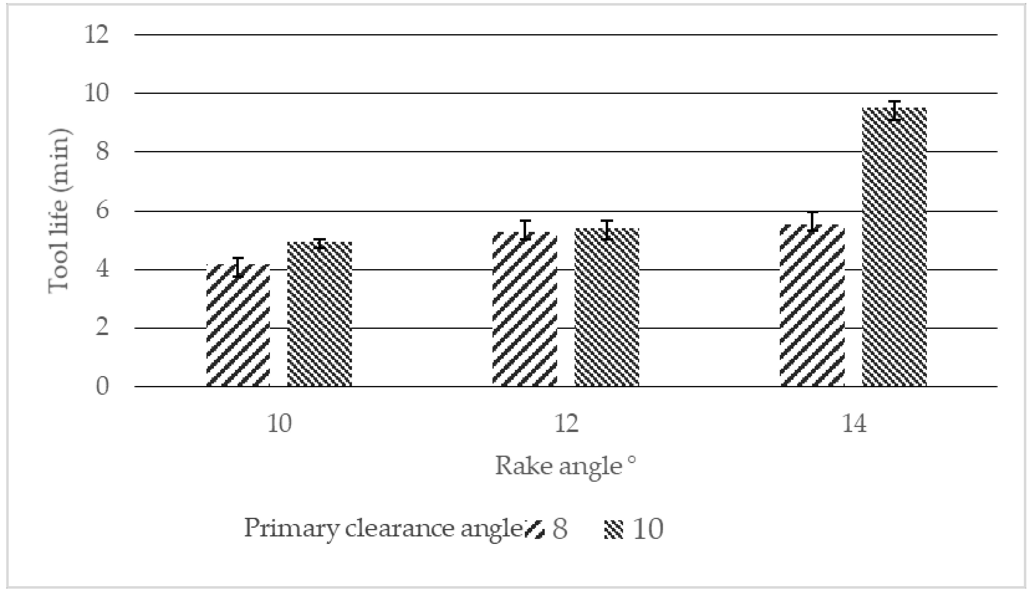
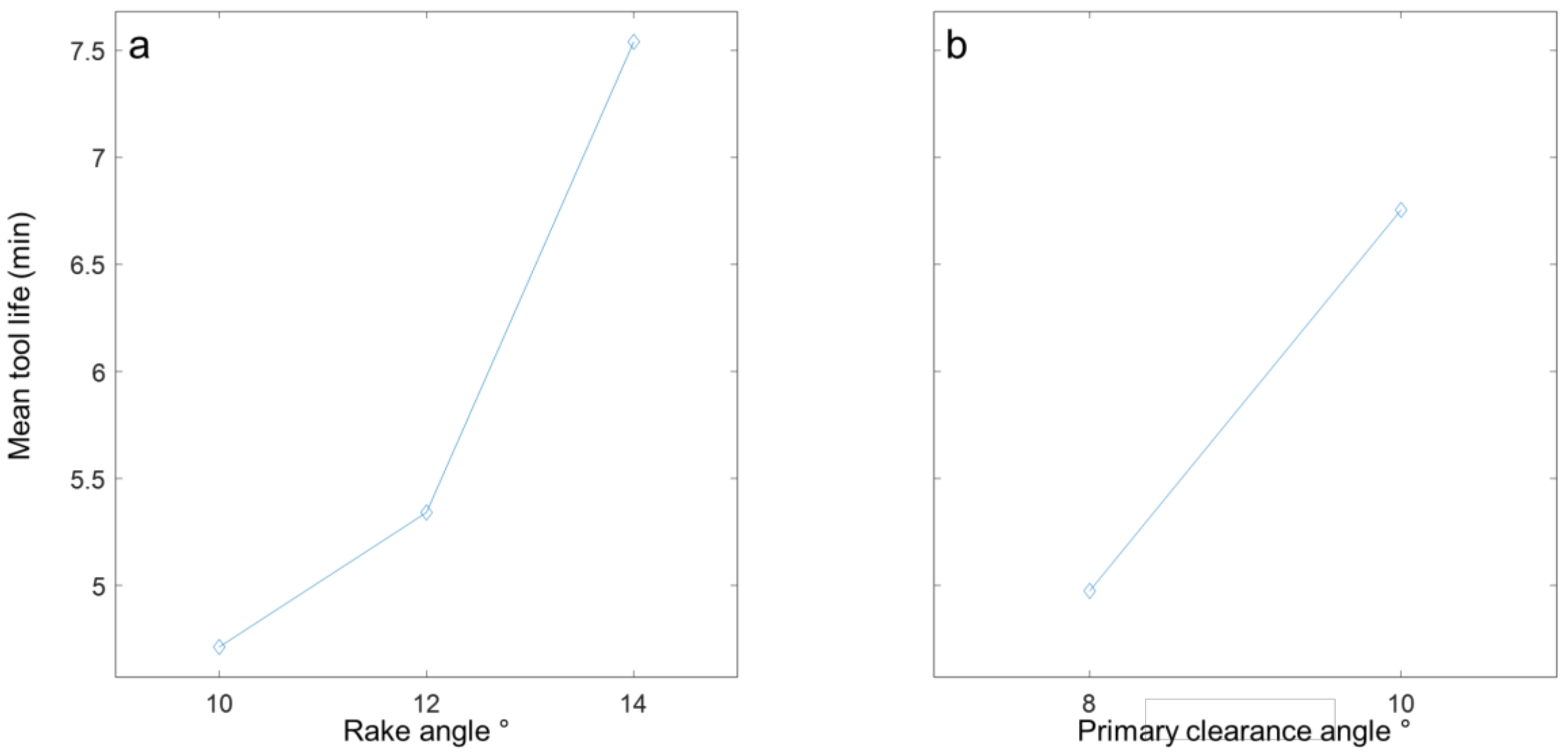
3.1.1. Tool Life
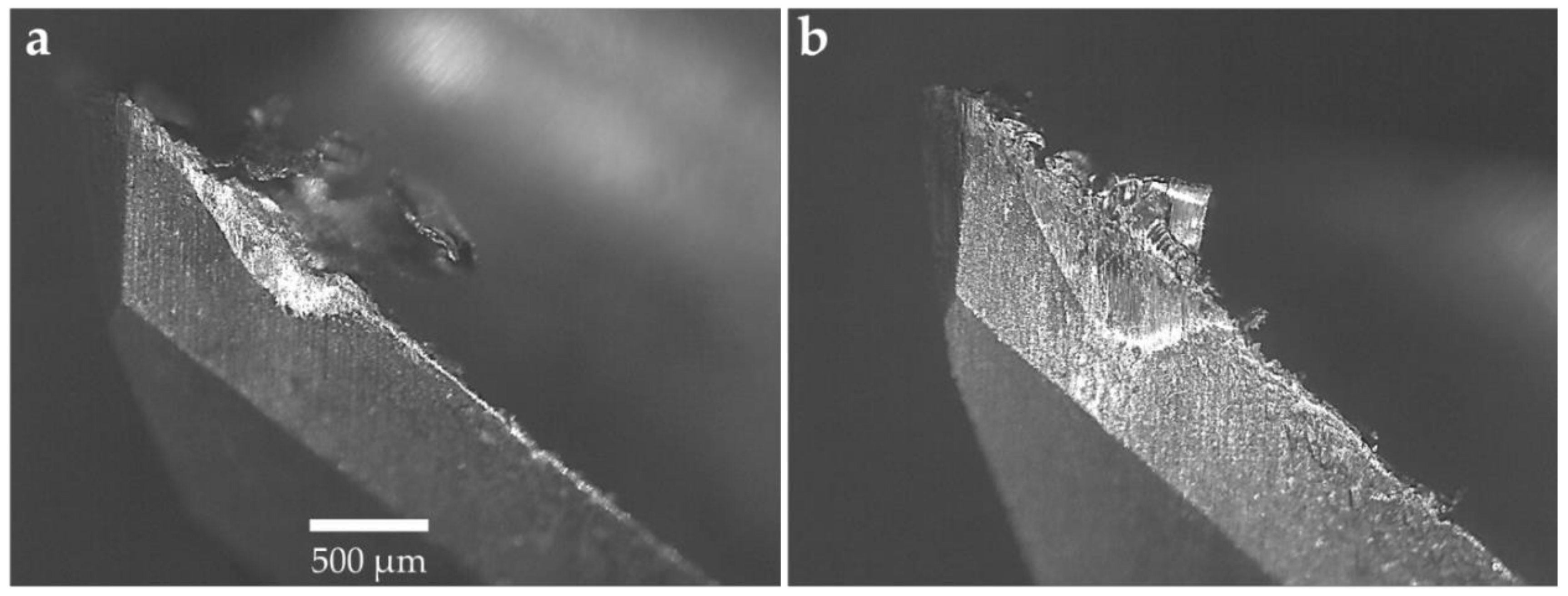
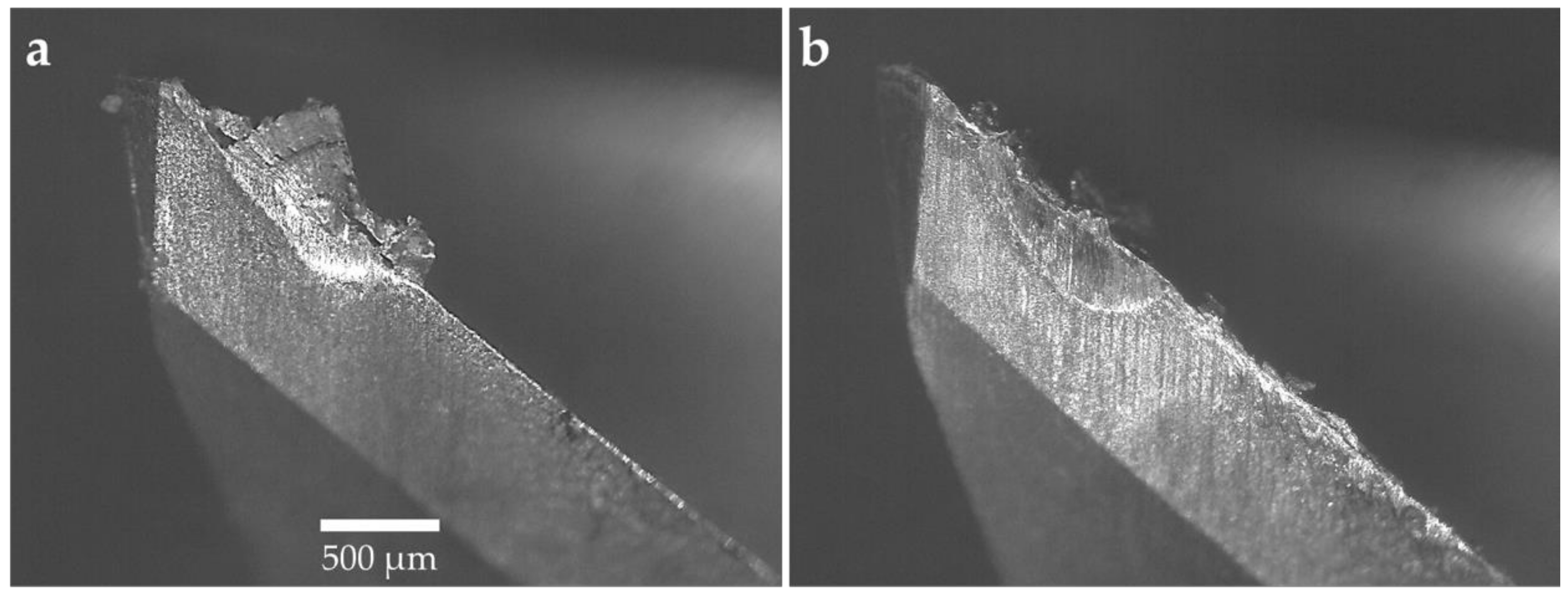
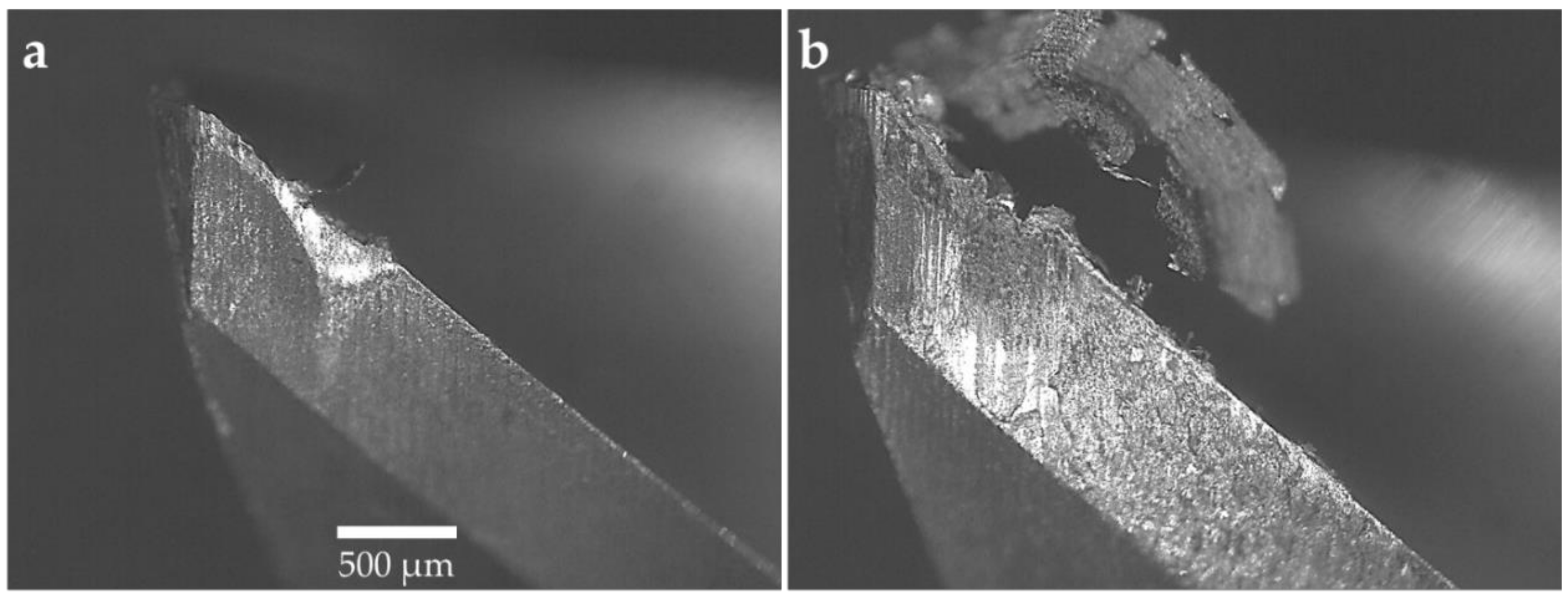
3.1.2. Tool Wear
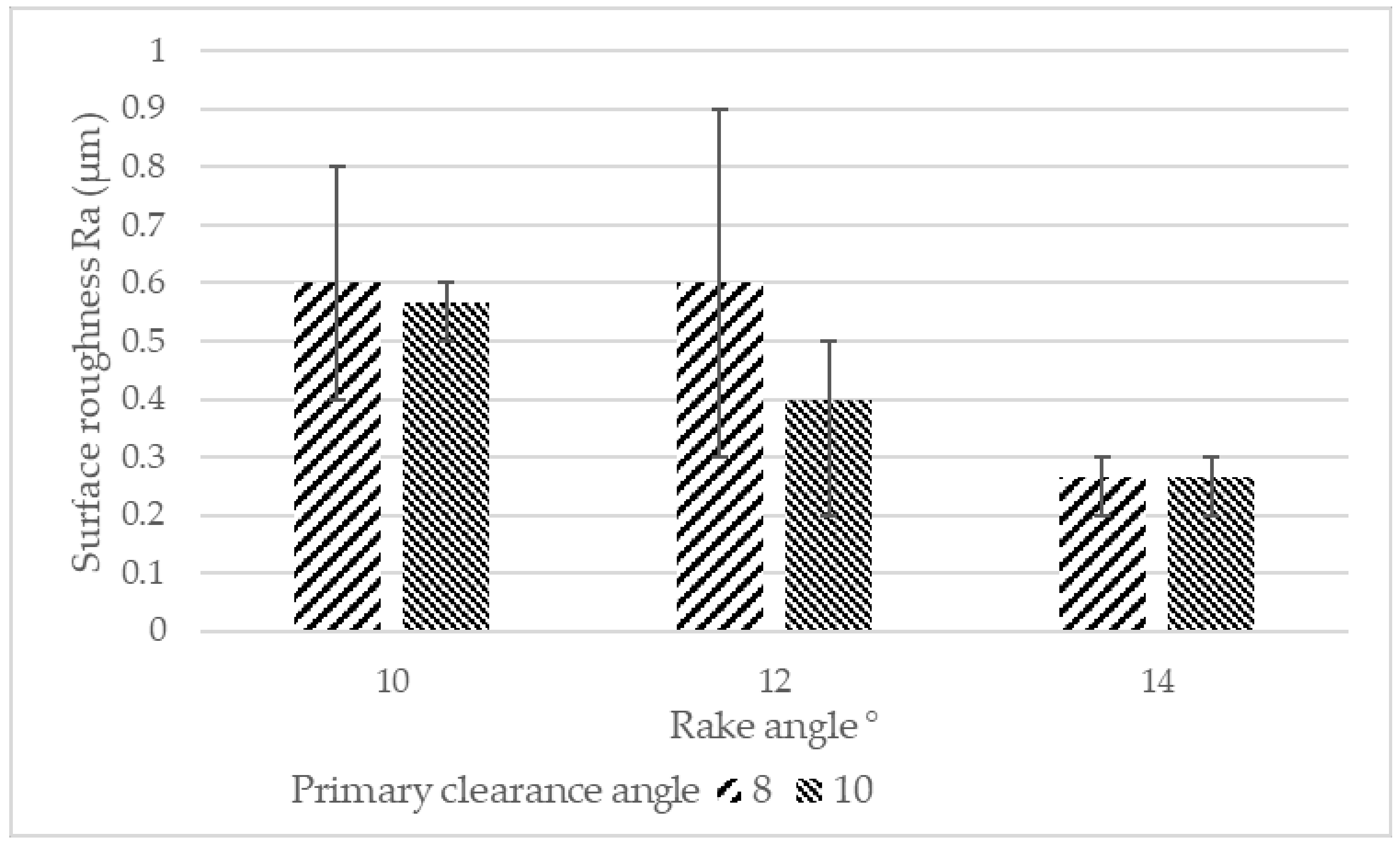
3.1.3. Surface Roughness
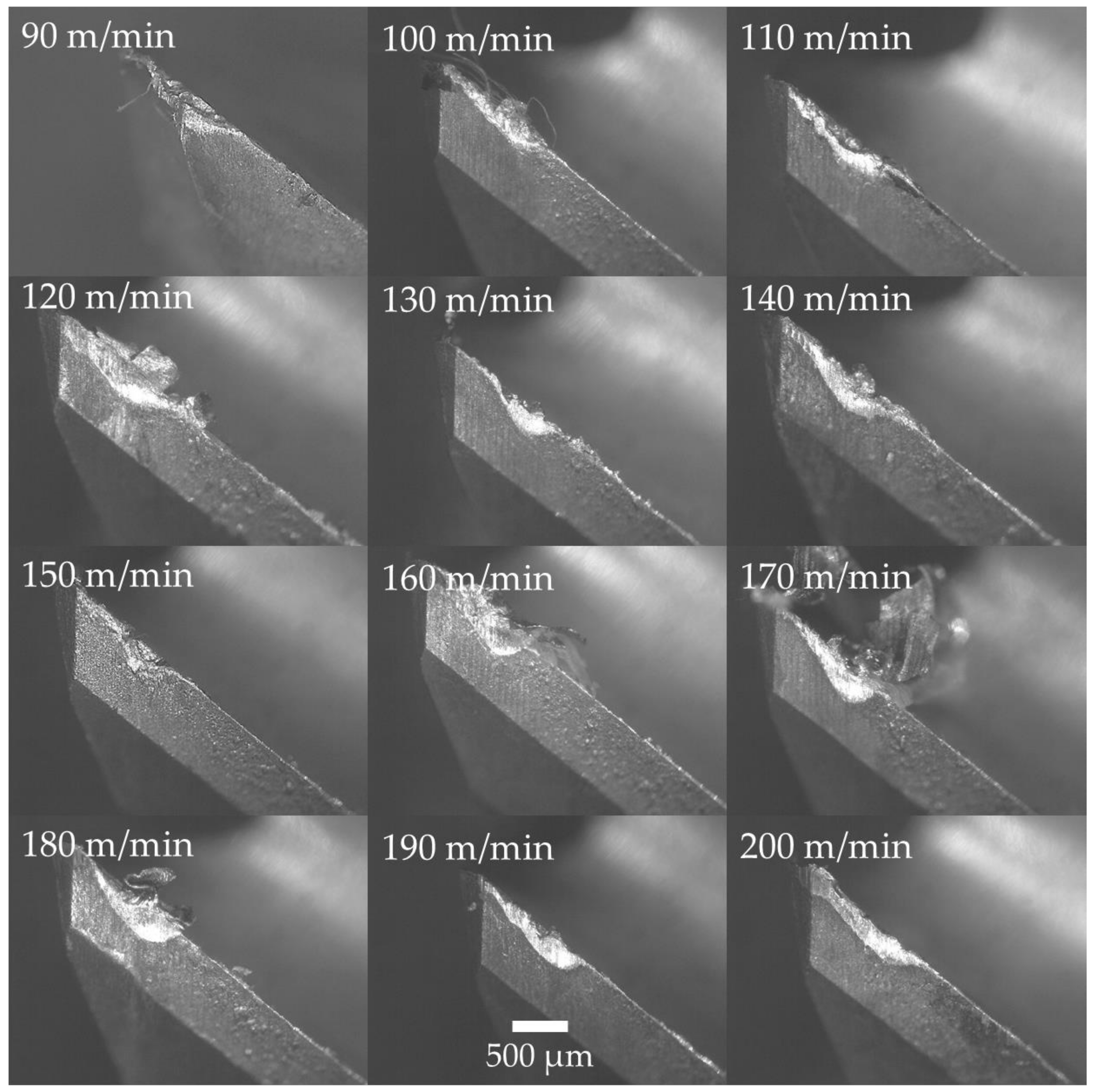
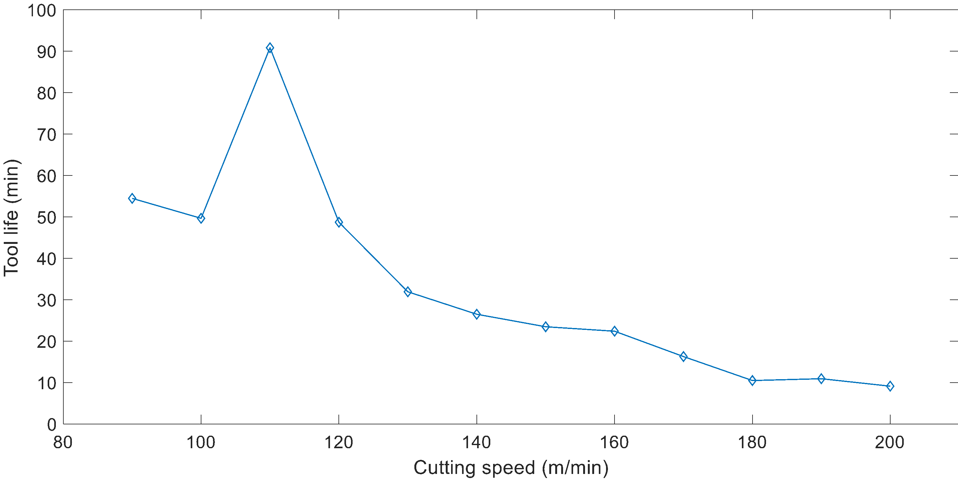
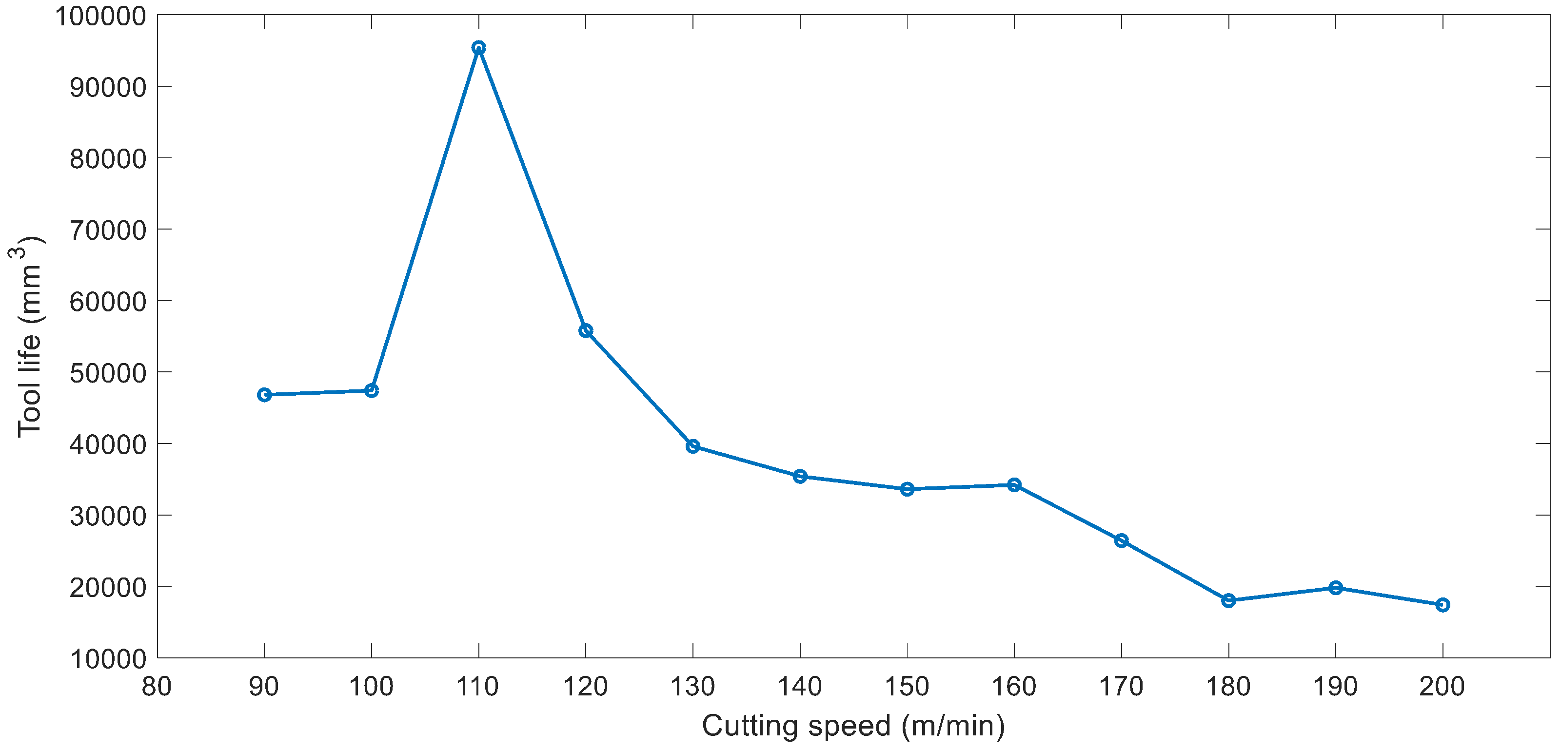
3.2. Cutting Speed
4. Discussion
5. Conclusions
Author Contributions
Funding
Acknowledgments
Conflicts of Interest
References
- Lütjering, G.; Williams, J.C. Titanium, 2nd ed.; Springer: New York, NY, USA, 2007. [Google Scholar]
- Criou, O. A350 XWB Family & Technologies; Airbus S.A.S: Leiden, The Netherlands, 2007. [Google Scholar]
- Scot, A. Boeing looks at pricey titanium in bid to stem 787 losses. Reuters. 2015. Available online: https://www.reuters.com/article/us-boeing-787-titanium-insight/boeing-looks-at-pricey-titanium-in-bid-to-stem-787-losses-idUSKCN0PY1PL20150724 (accessed on 2 February 2019).
- Ezugwu, E.; Bonney, J.; Yamane, Y. An overview of the machinability of aeroengine alloys. J. Mater. Process. Technol. 2003, 134, 233–253. [Google Scholar] [CrossRef]
- Sadik, M.I.; Isakson, S.; Malakizadi, A.; Nyborg, L. Influence of coolant flow rate on tool life and wear development in cryogenic and wet milling of Ti-6Al-4V. Procedia CIRP 2016, 46, 91–94. [Google Scholar] [CrossRef]
- Revuru, R.S.; Posinasetti, N.R.; VSN, V.R.; M, A. Application of cutting fluids in machining of titanium alloys—A review. Int. J. Adv. Manuf. Technol. 2017, 91, 2477–2498. [Google Scholar] [CrossRef]
- Li, G.; Yi, S.; Wen, C.; Ding, S. Wear mechanism and modeling of tribological behavior of polycrystalline diamond tools when cutting Ti6Al4V. J. Manuf. Sci. Eng. 2018, 140, 121011. [Google Scholar] [CrossRef]
- Liu, J.; Jiang, X.; Han, X.; Gao, Z.; Zhang, D. Effects of rotary ultrasonic elliptical machining for side milling on the surface integrity of Ti-6Al-4V. Int. J. Adv. Manuf. Technol. 2018. [Google Scholar] [CrossRef]
- Machai, C.; Biermann, D. Machining of β-titanium-alloy Ti–10V–2Fe–3Al under cryogenic conditions: Cooling with carbon dioxide snow. J. Mater. Process. Technol. 2011, 211, 1175–1183. [Google Scholar] [CrossRef]
- Biermann, D.; Abrahams, H.; Metzger, M. Experimental investigation of tool wear and chip formation in cryogenic machining of titanium alloys. Adv. Manuf. 2015, 3, 292–299. [Google Scholar] [CrossRef]
- Jawahir, I.S.; Attia, H.; Biermann, D.; Duflou, J.; Klocke, F.; Meyer, D.; Newman, S.T.; Pusavec, F.; Putz, M.; Rech, J.; et al. Cryogenic manufacturing processes. CIRP Ann. 2016, 65, 713–736. [Google Scholar] [CrossRef]
- Pereira, O.; Rodríguez, A.; Fernández-Abia, A.I.; Barreiro, J.; López de Lacalle, L.N. Cryogenic and minimum quantity lubrication for an eco-efficiency turning of aisi 304. J. Clean. Prod. 2016, 139, 440–449. [Google Scholar] [CrossRef]
- Pereira, O.; Català, P.; Rodríguez, A.; Ostra, T.; Vivancos, J.; Rivero, A.; López-de-Lacalle, L.N. The use of hybrid CO2+MQL in machining operations. Procedia Eng. 2015, 132, 492–499. [Google Scholar] [CrossRef]
- Yildiz, Y.; Nalbant, M. A review of cryogenic cooling in machining processes. Int. J. Mach. Tools Manuf. 2008, 48, 947–964. [Google Scholar] [CrossRef]
- Lu, T.; Kudaravalli, R.; Georgiou, G. Cryogenic machining through the spindle and tool for improved machining process performance and sustainability: Pt. I, system design. Procedia Manuf. 2018, 21, 266–272. [Google Scholar] [CrossRef]
- Jawahir, I.; Brinksmeier, E.; M’Saoubi, R.; Aspinwall, D.; Outeiro, J.; Meyer, D.; Umbrello, D.; Jayal, A. Surface integrity in material removal processes: Recent advances. CIRP Ann. 2011, 60, 603–626. [Google Scholar] [CrossRef]
- Kaynak, Y.; Karaca, H.E.; Noebe, R.D.; Jawahir, I.S. Tool-wear analysis in cryogenic machining of niti shape memory alloys: A comparison of tool-wear performance with dry and MQL machining. Wear 2013, 306, 51–63. [Google Scholar] [CrossRef]
- Pu, Z.; Outeiro, J.C.; Batista, A.C.; Dillon, O.W. Jr.; Puleo, D.A.; Jawahir, I.S. Enhanced surface integrity of AZ31B mg alloy by cryogenic machining towards improved functional performance of machined components. Int. J. Mach. Tools Manuf. 2012, 56, 17–27. [Google Scholar] [CrossRef]
- Mia, M.; Dhar, N.R. Influence of single and dual cryogenic jets on machinability characteristics in turning of Ti-6Al-4V. Proc. Inst. Mech. Eng. Part B J. Eng. Manuf. 2019, 233, 711–726. [Google Scholar] [CrossRef]
- Lee, I.; Bajpai, V.; Moon, S.; Byun, J.; Lee, Y.; Park, H.W. Tool life improvement in cryogenic cooled milling of the preheated Ti–6Al–4V. Int. J. Adv. Manuf. Technol. 2015, 79, 665–673. [Google Scholar] [CrossRef]
- Park, K.-H.; Yang, G.-D.; Lee, M.-G.; Jeong, H.; Lee, S.-W.; Lee, D.Y. Eco-friendly face milling of titanium alloy. Int. J. Precis. Eng. Manuf. 2014, 15, 1159–1164. [Google Scholar] [CrossRef]
- Iqbal, A.; Zhao, W.; Zaini, J.; He, N.; Nauman, M.M.; Suhaimi, H. Comparative analyses of multi-pass face-turning of a titanium alloy under various cryogenic cooling and micro-lubrication conditions. Int. J. Lightweight Mater. Manuf. 2018. [Google Scholar] [CrossRef]
- Zhao, Z.; Hong, S. Cooling strategies for cryogenic machining from a materials viewpoint. J. Mater. Eng. Perform. 1992, 1, 669–678. [Google Scholar] [CrossRef]
- Rotella, G.; Dillon, O.W., Jr.; Umbrello, D.; Settineri, L.; Jawahir, I.S. The effects of cooling conditions on surface integrity in machining of Ti6Al4V alloy. Int. J. Adv. Manuf. Technol. 2014, 71, 47–55. [Google Scholar] [CrossRef]
- Bordin, A.; Bruschi, S.; Ghiotti, A.; Bariani, P.F. Analysis of tool wear in cryogenic machining of additive manufactured Ti6Al4V alloy. Wear 2015, 328–329, 89–99. [Google Scholar] [CrossRef]
- Bordin, A.; Sartori, S.; Bruschi, S.; Ghiotti, A. Experimental investigation on the feasibility of dry and cryogenic machining as sustainable strategies when turning Ti6Al4V produced by additive manufacturing. J. Clean. Prod. 2017, 142, 4142–4151. [Google Scholar] [CrossRef]
- Pereira, O.; Rodríguez, A.; Barreiro, J.; Fernández-Abia, A.I.; de Lacalle, L.N.L. Nozzle design for combined use of MQL and cryogenic gas in machining. Int. J. Precis. Eng. Manuf.-Green Technol. 2017, 4, 87–95. [Google Scholar] [CrossRef]
- Astakhov, V.P.; Godlevskiy, V. 3—Delivery of metalworking fluids in the machining zone. In Metalworking Fluids (MWFS) for Cutting and Grinding; Astakhov, V.P., Joksch, S., Eds.; Woodhead Publishing: Sawston, UK, 2012; pp. 79–134. [Google Scholar]
- Hong, S.Y.; Ding, Y. Cooling approaches and cutting temperatures in cryogenic machining of Ti-6Al-4V. Int. J. Mach. Tools Manuf. 2001, 41, 1417–1437. [Google Scholar] [CrossRef]
- Dhananchezian, M.; Kumar, M.P. Cryogenic turning of the Ti–6Al–4V alloy with modified cutting tool inserts. Cryogenics 2011, 51, 34–40. [Google Scholar] [CrossRef]
- Bellin, M.; Sartori, S.; Ghiotti, A.; Bruschi, S. New tool holder design for cryogenic machining of Ti6Al4V. AIP Conf. Proc. 2017, 1896, 090001. [Google Scholar]
- Wang, Z.; Rajurkar, K. Cryogenic machining of hard-to-cut materials. Wear 2000, 239, 168–175. [Google Scholar] [CrossRef]
- Ahmed, M.; Ismail, A.; Abakr, Y.; Amin, A. Effectiveness of cryogenic machining with modified tool holder. J. Mater. Process. Technol. 2007, 185, 91–96. [Google Scholar] [CrossRef]
- Venugopal, K.; Paul, S.; Chattopadhyay, A. Growth of tool wear in turning of Ti-6Al-4V alloy under cryogenic cooling. Wear 2007, 262, 1071–1078. [Google Scholar] [CrossRef]
- Wang, Z.Y.; Rajurkar, K.; Fan, J.; Lei, S.; Shin, Y.C.; Petrescu, G. Hybrid machining of inconel 718. Int. J. Mach. Tools Manuf. 2003, 43, 1391–1396. [Google Scholar] [CrossRef]
- Lu, T.; Kudaravalli, R.; Georgiou, G. Cryogenic machining through the spindle and tool for improved machining process performance and sustainability: Pt. II, sustainability performance study. Procedia Manuf. 2018, 21, 273–280. [Google Scholar] [CrossRef]
- Georgiou, G.; Azzopardi, D. Temperature Management for a Cryogenically Cooled Boring Tool. US 2018 / 0345387 A1, 06 December 2018. [Google Scholar]
- Hong, S.Y. Economical and ecological cryogenic machining. J. Manuf. Sci. Eng. 2001, 123, 331. [Google Scholar] [CrossRef]
- Bermingham, M.; Palanisamy, S.; Kent, D.; Dargusch, M. A comparison of cryogenic and high pressure emulsion cooling technologies on tool life and chip morphology in Ti-6Al-4V cutting. J. Mater. Process. Technol. 2011, 212, 752–765. [Google Scholar] [CrossRef]
- Cordes, S.; Hübner, F.; Schaarschmidt, T. Next generation high performance cutting by use of carbon dioxide as cryogenics. Procedia CIRP 2014, 14, 401–405. [Google Scholar] [CrossRef]
- Kaynak, Y.; Lu, T.; Jawahir, I. Cryogenic machining-induced surface integrity: A review and comparison with dry, mql, and flood-cooled machining. Mach. Sci. Technol. 2014, 18, 149–198. [Google Scholar] [CrossRef]
- Shokrani, A.; Dhokia, V.; Newman, S.T. Energy conscious cryogenic machining of Ti-6Al-4V titanium alloy. Proc. Inst. Mech. Eng. Part B J. Eng. Manuf. 2018, 232, 1690–1706. [Google Scholar] [CrossRef]
- Zhao, Z.; Hong, S. Cryogenic properties of some cutting tool materials. J. Mater. Eng. Perform. 1992, 1, 705–714. [Google Scholar] [CrossRef]
- Shokrani, A.; Dhokia, V.; Newman, S.T. Comparative investigation on using cryogenic machining in cnc milling of Ti-6Al-4V titanium alloy. Mach. Sci. Technol. 2016, 20, 475–494. [Google Scholar] [CrossRef]
- Schulz, H.; Moriwaki, T. High-speed machining. CIRP Ann. 1992, 41, 637–643. [Google Scholar] [CrossRef]
- International-Organization-for-Standardization. Tool Life Testing in Milling—Part 2: End Milling; ISO-8688-2; International-Organization-for-Standardization: Geneva, Switzerland, 1989. [Google Scholar]
- Sabberwal, A.J.P.; Fleischer, P. The effect of material and geometry on the wear characteristics of cutting tools during face milling. Int. J. Mach. Tool Des. Res. 1964, 4, 47–71. [Google Scholar] [CrossRef]
- Krain, H.; Sharman, A.; Ridgway, K. Optimisation of tool life and productivity when end milling inconel 718tm. J. Mater. Process. Technol. 2007, 189, 153–161. [Google Scholar] [CrossRef]
- Ezugwu, E.O.; Pashby, I.R. High speed milling of nickel-based superalloys. J. Mater. Process. Technol. 1992, 33, 429–437. [Google Scholar] [CrossRef]
- Saglam, H.; Unsacar, F.; Yaldiz, S. Investigation of the effect of rake angle and approaching angle on main cutting force and tool tip temperature. Int. J. Mach. Tools Manuf. 2006, 46, 132–141. [Google Scholar] [CrossRef]
- Kaymakci, M.; Kilic, Z.M.; Altintas, Y. Unified cutting force model for turning, boring, drilling and milling operations. Int. J. Mach. Tools Manuf. 2012, 54-55, 34–45. [Google Scholar] [CrossRef]
- Hong, S.Y.; Markus, I.; Jeong, W. New cooling approach and tool life improvement in cryogenic machining of titanium alloy Ti-6Al-4V. Int. J. Mach. Tools Manuf. 2001, 41, 2245–2260. [Google Scholar] [CrossRef]
- Abele, E.; Fröhlich, B. High speed milling of titanium alloys. Adv. Prod. Eng. Manag. 2008, 3, 131–140. [Google Scholar]
- Shalaby, M.A.; Veldhuis, S.C. Some observations on flood and dry finish turning of the Ti-6Al-4V aerospace alloy with carbide and pcd tools. Int. J. Adv. Manuf. Technol. 2018, 99, 2939–2957. [Google Scholar] [CrossRef]
- Nouari, M.; Makich, H. Analysis of physical cutting mechanisms and their effects on the tool wear and chip formation process when machining aeronautical titanium alloys: Ti-6Al-4V and Ti-55531. In Machining of Titanium Alloys; Davim, J.P., Ed.; Springer: Berlin/Heidelberg, Germany, 2014; pp. 79–111. [Google Scholar]
- Bermingham, M.J.; Kirsch, J.; Sun, S.; Palanisamy, S.; Dargusch, M.S. New observations on tool life, cutting forces and chip morphology in cryogenic machining Ti-6Al-4V. Int. J. Mach. Tools Manuf. 2011, 51, 500–511. [Google Scholar] [CrossRef]
- Astakhov, V.P. The assessment of cutting tool wear. Int. J. Mach. Tools Manuf. 2004, 44, 637–647. [Google Scholar] [CrossRef]
- Rahman, M.; Wong, Y.S.; Zareena, A.R. Machinability of titanium alloys. JSME Int. J. Ser. C 2003, 46, 107–115. [Google Scholar] [CrossRef]
- Zoya, Z.A.; Krishnamurthy, R. The performance of cbn tools in the machining of titanium alloys. J. Mater. Process. Technol. 2000, 100, 80–86. [Google Scholar] [CrossRef]


| Cutting speed | Chip load | Axial depth of cut | Radial depth of cut |
|---|---|---|---|
| 200 m/min | 0.03 mm/tooth | 1 mm | 4 mm |
| Source | Sum of squares | Degree of freedom | Mean square | P |
|---|---|---|---|---|
| Rake angle | 28.72 | 2 | 14.36 | 0.0004 |
| Primary clearance angle | 11.60 | 1 | 11.60 | 0.0045 |
| Error | 14.26 | 14 | 1.02 | |
| Total | 54.58 | 17 |
© 2019 by the authors. Licensee MDPI, Basel, Switzerland. This article is an open access article distributed under the terms and conditions of the Creative Commons Attribution (CC BY) license (http://creativecommons.org/licenses/by/4.0/).
Share and Cite
Shokrani, A.; Newman, S.T. A New Cutting Tool Design for Cryogenic Machining of Ti–6Al–4V Titanium Alloy. Materials 2019, 12, 477. https://doi.org/10.3390/ma12030477
Shokrani A, Newman ST. A New Cutting Tool Design for Cryogenic Machining of Ti–6Al–4V Titanium Alloy. Materials. 2019; 12(3):477. https://doi.org/10.3390/ma12030477
Chicago/Turabian StyleShokrani, Alborz, and Stephen T Newman. 2019. "A New Cutting Tool Design for Cryogenic Machining of Ti–6Al–4V Titanium Alloy" Materials 12, no. 3: 477. https://doi.org/10.3390/ma12030477
APA StyleShokrani, A., & Newman, S. T. (2019). A New Cutting Tool Design for Cryogenic Machining of Ti–6Al–4V Titanium Alloy. Materials, 12(3), 477. https://doi.org/10.3390/ma12030477