1. Introduction
Automotive disc brakes are known to experience severe working conditions under thermal fatigue, wear, and heavy mechanical loadings. Amongst different materials, cast iron is the most widely used material in disc brakes, since it has a unique combination of excellent wear resistance and a superior heat transfer coefficient [
1]. Different parameters including alloying elements and graphite morphology, affect tribological behaviors of cast iron. There are several studies on the effects of graphite morphologies and alloying elements on the wear resistance of gray cast irons [
2,
3,
4,
5]. Silicon, chromium, and manganese are known to have a positive attribution to the wear resistance of cast irons. It is postulated that higher hardness and tensile strength in combination with less wear loss can be achieved by adding silicon and chromium to gray cast iron [
6,
7,
8]. Further to the chemistry and microstructure of the alloy, abrasion and wear test variables also have prominent attributions to the wear behavior of gray cast irons. Whether the test is carried out in dry or lubricated conditions, the velocity of counter-moving parts during the test and applied load all have controlling effects on the wear behavior of alloys. For instance, gray cast iron shows much better wear resistance in lubricated conditions, obviously because of the lower friction coefficient [
9,
10,
11,
12]. Gray cast iron alloys are known to have a self-lubricating characteristic due to the presence of graphite flakes in their microstructures, making them an appropriate choice for sliding components in mechanical assemblies and installations [
3,
13,
14]. That is why cast irons are still by far the most widely used material in disc brakes in trains and automobiles. Given that the disc brake is an essential component when the safety of passengers in the vehicle is a concern, understanding the degradation mechanisms of this component is a very key issue in producing more reliable and safer vehicles [
15,
16]. The degradation and failure of disc brakes can be very complicated because of the simultaneous contributions of mechanical loading, surface conditions, and thermal stresses. The fact that disc brakes experience dynamic loading conditions makes the interpretation of failures even more complicated. It is postulated that the surface spallation, formed during abrasion, creates spots on which cracks can be initiated. Further loading causes crack growth and failure of the disc [
16,
17,
18]. Gao et al. [
19] reported that the reason for crack formation and growth is the fatigue due to thermomechanical cyclic loading. This paper investigated a failure in a ventilated disc brake in an automobile and we presented a systematic and comprehensive assessment of the failure, considering the microstructure and loading conditions.
2. Materials and Methods
Samples for microstructural and mechanical properties characterizations were cut from a failed disc brake, using electro-discharge machining (EDM). Optical microscopes, scanning electron microscope (SEM, Philips, Eindhoven, The Netherlands), and energy dispersive X-ray spectroscopy (EDS, Cu Kα) were used to study the microstructure and wear mechanisms in the failed disc. The fracture surface of the failed specimens was also studied using SEM. The hardness of specimens was measured using a Vickers micro-hardness test (force 100 g with loading time 15 sec, according to ASTM E384-17). A laser profilometer was used to investigate the surface topology of failed samples. To further investigate the correlation between the microstructure and wear behavior of samples, a pin-on-disc wear test was conducted on samples of 50 mm diameter at ambient temperature, using a hardened AISI 52100 steel (Fe-1.0C, 0.4Mn, 0.15Si, 0.02S, 0.01P, 1.5Cr, in wt%) pin, with 5 mm diameter and hardness 64 RC. The specimens were taken from the disc. Wear tests were performed on the side which was not in contact with the pad. First, some trial wear tests with different loads were conducted to find the load at which the wear test yielded results in a reasonable time. Loads were changed in the trial tests from 10 to 60 N. Each test was run for 50 m. In the end, tests were carried out with 20 and 40 N loads. Results showed that experiments with loadings below 10 N took a very long time to see minor changes in the specimen weight. At the other end, loadings higher than 60 N resulted in a rapid deformation and excessive wear over a few minutes, in such a way that hardly any information (the kinetics of weight loss, for example) could be drawn from the test. The tests were continued up to 1000 m. Wear tests were interrupted after every 250 m to measure weight loss. The velocity of the moving pin on the disc was chosen to be a constant amount of 0.25 m/s. Wear debris, collected during wear tests, were also evaluated using SEM. SEM also investigated the surface topologies after wear tests.
4. Results and Discussion
Figure 2 shows optical microscope images of the disc before and after etching. As shown, graphite flakes were distributed in a pearlite matrix. Graphite flakes are excellent thermal conductors, making gray irons good thermal conductors as well. This also has to do with the fact that graphite flakes form an interconnected network, forming an easy path for heat transfer. Moreover, graphite flakes are known to absorb sounds created by the brake pad-brake disc contacts [
20].
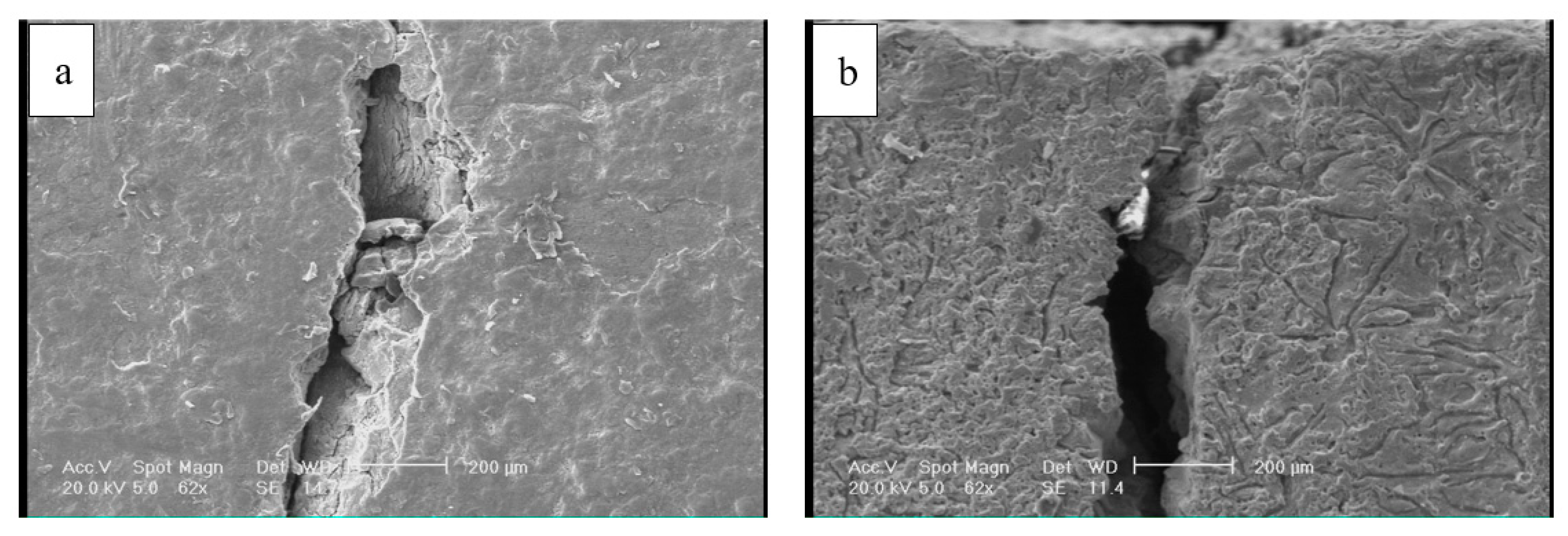
Figure 3 shows the SEM images of cracks on the surface of the disc from the top view and from the cross-section. The former image shows that crack openings on the surface in some areas were as large as 200 µm. It appeared that these large openings on the surface were formed due to the spallation of rather large chips from the surface. The remainder of these chip-like features were still visible inside the crack. Further away at the right side of the crack, there was a spot (roughly 200 µm × 100 µm), which was seemingly the area from which a surface chip spallation had taken place.
Figure 3b and
Figure 4 are images of the cross-section of the crack. There was no branching or any major deviation from the straight line.
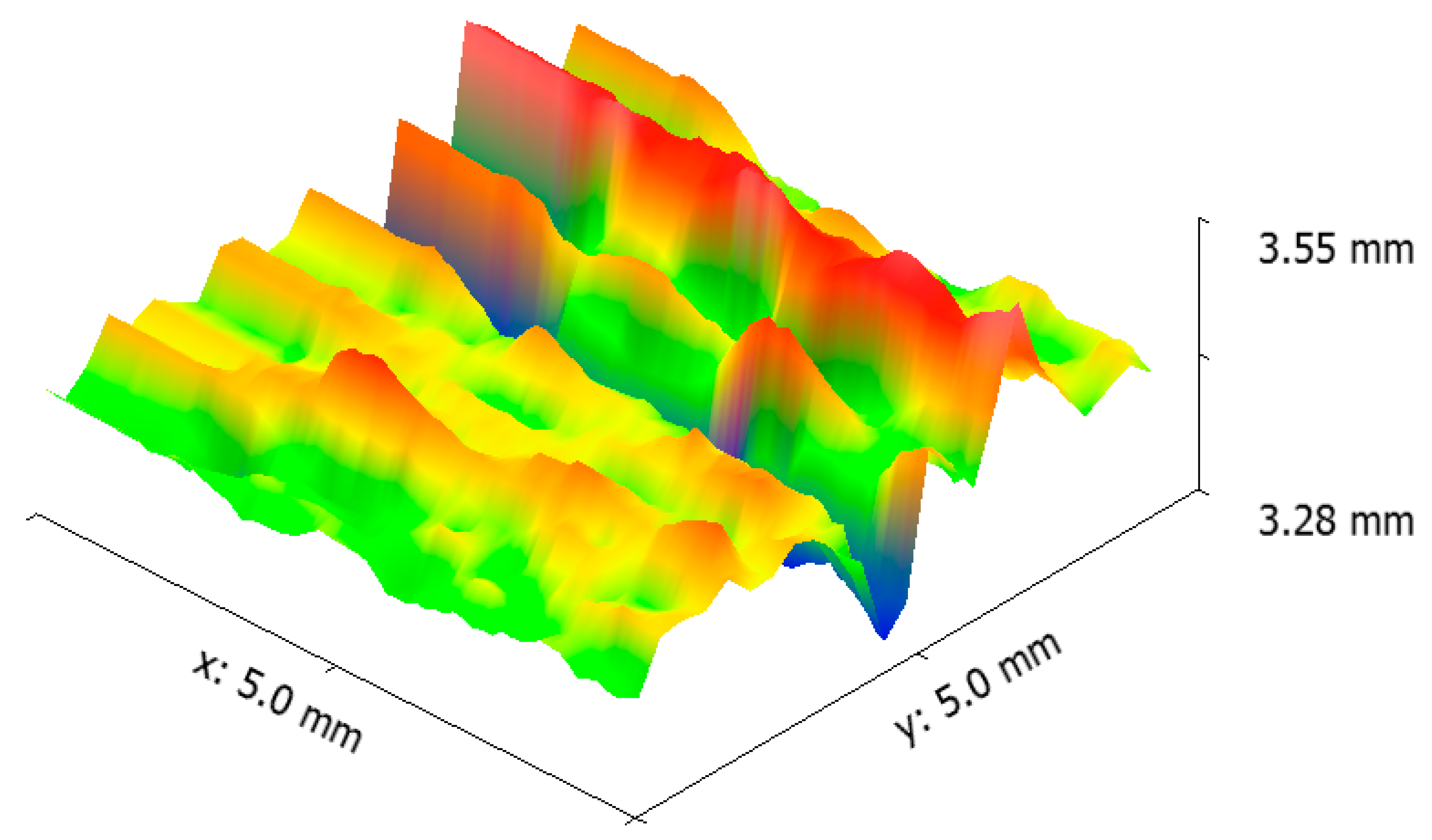
Figure 5 shows the laser profilometry of the surface topography in the vicinity of the crack. There were deep ups and downs parallel to each other [
21]. Sharp edges on the surface were indications of surface cutting and abrasive wear on the surface.
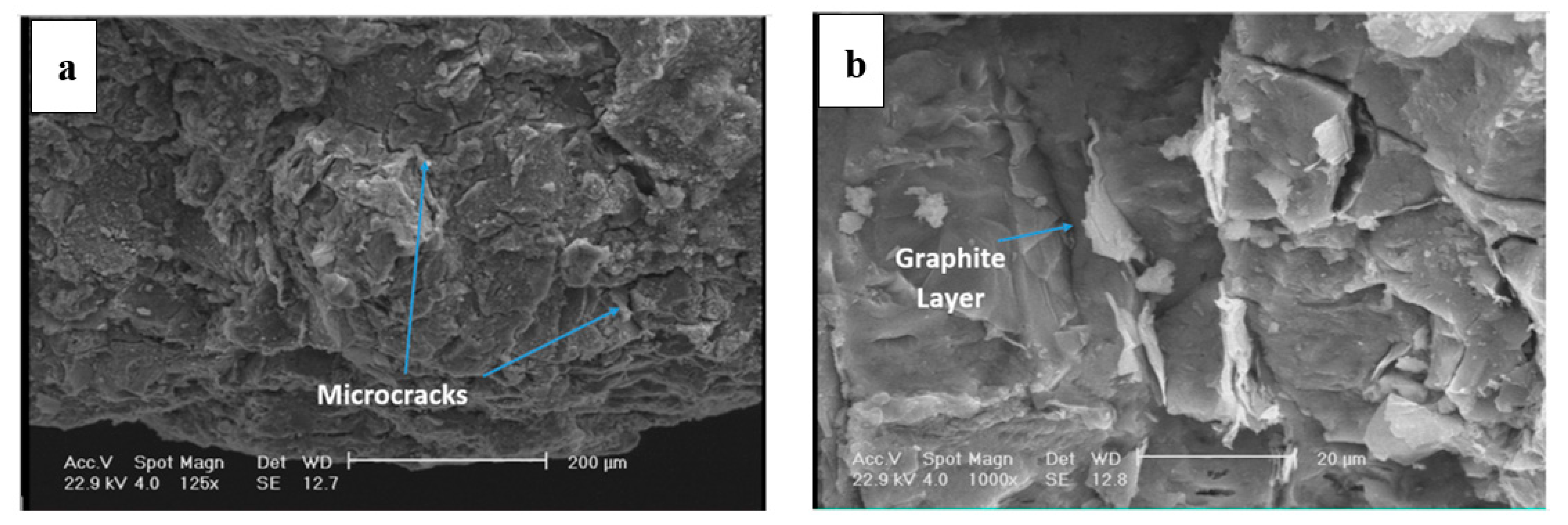
Figure 6 shows the fracture surface of the disc. Fracture is overall brittle with a layered structure (see
Figure 6a). The fracture surface was covered with a network of fine microcracks. The interface of matrix-graphite, in which matrix is referred to pearlite, is a suitable place for crack initiation, given that the adhesion of graphite to the iron-based structure is rather weak. An example is depicted in
Figure 6b. It appears that the fracture had mostly initiated from the graphite/matrix interface.
Figure 7 shows that the fracture surface in some areas is covered with fine agglomerated particles. EDS results show that these particles were mostly Fe- and Si-containing oxide particles. These particles were formed during the wear of the surface and detachment of the particles. This is while the high temperature of the disc during the contact of the pad and the disc resulted in the diffusion of the oxygen atoms into the lattice and the oxidation of the particles. Fine oxide particles have relatively higher hardness compared to the matrix. These particles can cause severe abrasion in case they are entrapped between two moving components, which in this case for the brake pad and the disc. The formation of fine oxide particles between the brake pad and the disc had to do with localized temperature increase due to the excessive friction at local contact points between the pad and the disc.
Results of microhardness profilometry across the crack at different depths from the surface are shown in
Figure 8. Disc brakes experience large surface compression stresses due to exerted loads from the brake pad. This results in plastic deformation and work hardening at layers close to the surface. In this case, this resulted in an increase in the hardness from about 200 VHN at deep layers inside the brake disc to 400 VHN in layers close to the surface. This increase in the hardness confirmed the argument that the surface was heavily deformed and work-hardened during service. Prasad [
4] also reported the occurrence of work hardening in gray cast iron discs during a wear test. The depth of the work-hardened layer was dependent on the loading conditions, the sliding distance (service time), and the temperature increase at local contact points.
To further investigate wear mechanisms in gray cast iron, pin-on-disc wear tests were performed on discs of 50 mm diameter. The tests were conducted for 1000 m under 20 and 40 N loads.
Figure 9 depicts the results of the wear tests.
Figure 9a compares the weight loss during wear tests under 20 and 40 N loads. The higher the load, the higher the weight loss. In the case of a 40 N load, the weight loss linearly increased with the sliding distance. However, in the case of a 20 N load, it appeared that the weight loss had different kinetics during the test, in such a way that the kinetics of weight loss was much slower in the first 500 m of sliding. The kinetics of weight loss significantly increased from this point on. This could be due to the activation of a new wear mechanism. Given that oxide particles have a significant contribution to the wear [
22], one can postulate that up to 500 m, not enough oxide particles were formed in between the pin and disc. This changed after 500 m of sliding. This argument follows the variation of the friction coefficient with sliding distance (see
Figure 9b). We see that where the load was 20 N, the coefficient of friction increased with different kinetics after 500 m. Concerning the coefficient of friction, one can see that the coefficient of friction with a load of 40 N was comparatively larger than that with a load of 20 N. This had to do with the correlation of the applied load and the coefficient of friction. As the applied load increased during the wear test, the contact points between the asperities increased, which resulted in a higher coefficient of friction. The observed increase in the coefficient of friction with sliding distance in both cases could be attributed to the formation and fragmentation of oxide particles on the surface. More importantly, as the sliding distance increased, the chance of detachment and fragmentation of the graphite flakes increased. Given that graphite flakes have a self-lubricating effect, this detachment and fragmentation of graphite flakes can increase the coefficient of friction. Graphite detachment can also increase the surface roughness and this will have a negative implication on the coefficient of friction.
Figure 9c,d show the laser profilometry of the surface topography and SEM image of the worn surface after 1000 m sliding under load 40 N. There were different features on the surface, with each being related to different wear mechanisms. First of all, there were some spots on the surface wherein the surface had clearly undergone severe plastic deformation. In some areas, this resulted in spallation on the surface (see
Figure 9d). Other than that, there were some plowings on the surface related to the abrasion due to the relative movement of oxide particles on the surface. Moreover, some surface cutting was identified on the surface. Cutting was identified when there was material separating with negligible plastic deformation at the sides of the grooves.
While plastic deformation and spallation are indications of an adhesive wear mechanism, plowing and cutting can be linked to the abrasive wear, inferring that both adhesive and abrasive wear mechanisms contribute to weight loss during wear test. The former wear mechanism has a relatively higher kinetics of weight loss. In severe conditions, contact points in-between sliding bodies can be severely damaged by adhesive wear. In case the surface has some minimum roughness and the applied load is high enough, metal-metal sticking on contact spots becomes inevitable. In case the so-called sticking layer is weakly bonded to the disc, it will eventually be detached from the surface. This is schematically shown in
Figure 10a. In comparison to the adhesive wear, abrasive wear takes place when a hard particle/asperity is sliding over a surface. Hard particles/asperities can cause abrasion without having to induce any major plastic deformation on the surface. In case particles/asperities are sharp enough, they create surface cutting. However, their attributions are not limited to cutting, as they could also cause surface micro-fractures and grain pull-outs (see
Figure 10b) [
23]. Cutting and micro-cracks are essentially more dominant features on the fracture surface. Surface cutting results in the detachment of wear debris. Where the wear debris is hard and fragile, they will be fragmented and entrapped in between sliding bodies and inside surface grooves, and, in turn, contribute to the abrasion of the surface. The attribution of wear debris to the wear rate depends on the relative hardness of wear particles to that of the worn surface. Fast abrasion is expected to take place when the hardness of the matrix is less than 80% of the hardness of particles [
23]. If the load at the contact points is high enough, the temperature at the contact points increases, and therefore, oxidation of the wear debris is also likely to take place. This appears to be the case in this failure (see
Figure 7). Oxide particles are clearly hard and are expected to cause further abrasion. Both cutting and micro-cracks are less probable when the worn surface is ductile in nature. Results show that in this case, both adhesive wear and abrasion control the wear of the disc brake during service.
Figure 11 shows the SEM images of debris after wear tests. Debris can primarily be categorized into large plate-like chips, with their sizes being in the range of a few ten micrometers, and fine agglomerated particles. EDS analysis shows that these particles are oxide particles, thereby supporting the aforementioned argument concerning the formation of oxide particles due to temperature increases in-between the pin and the disc.


