Gradient Microstructure in a Gear Steel Produced by Pressurized Gas Nitriding

 ,
,
Abstract
:1. Introduction
2. Experimental Procedure
3. Results
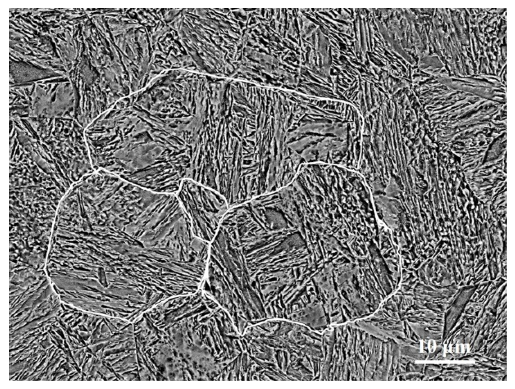
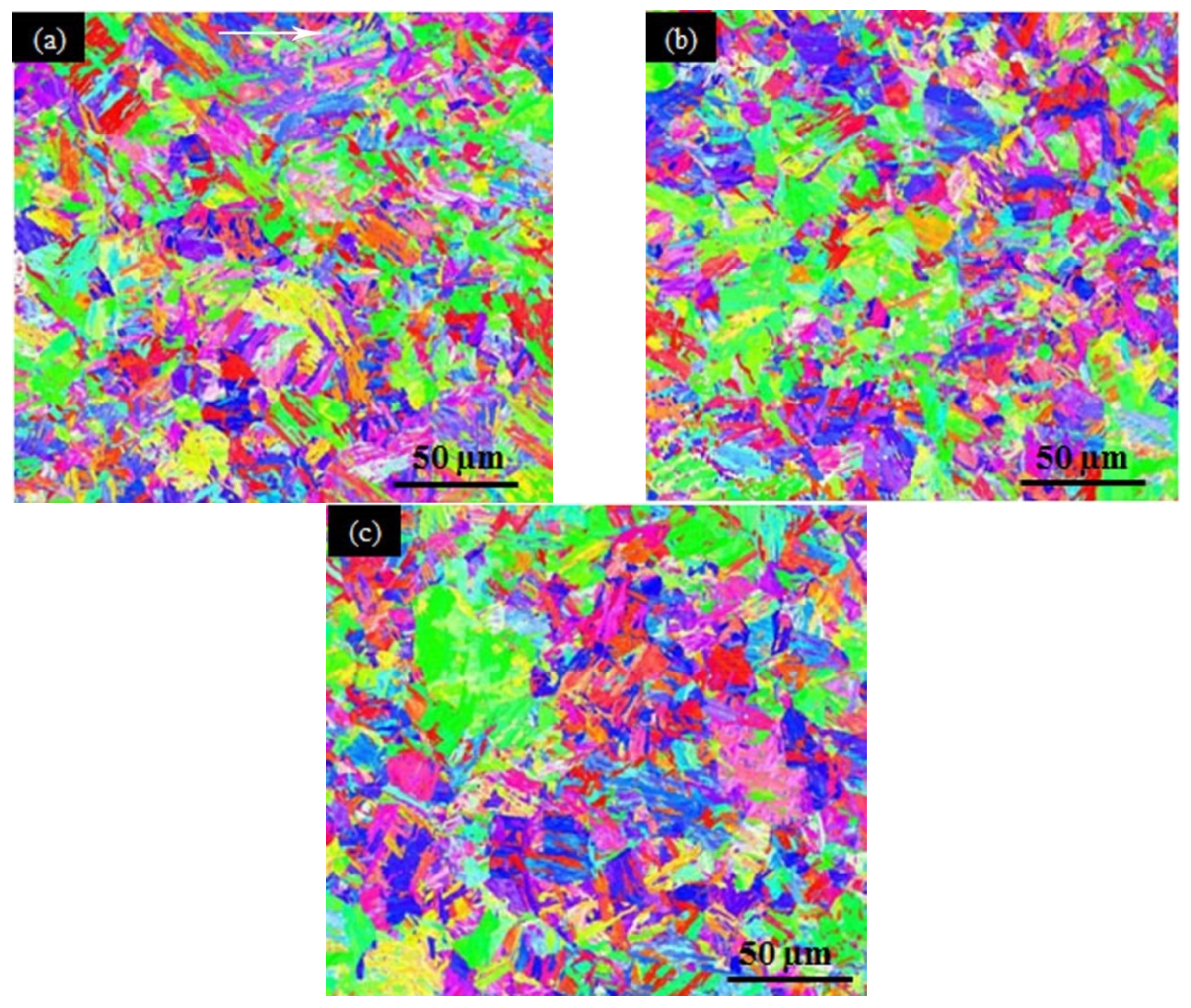
3.1. Initial State
3.2. Hardness Gradient
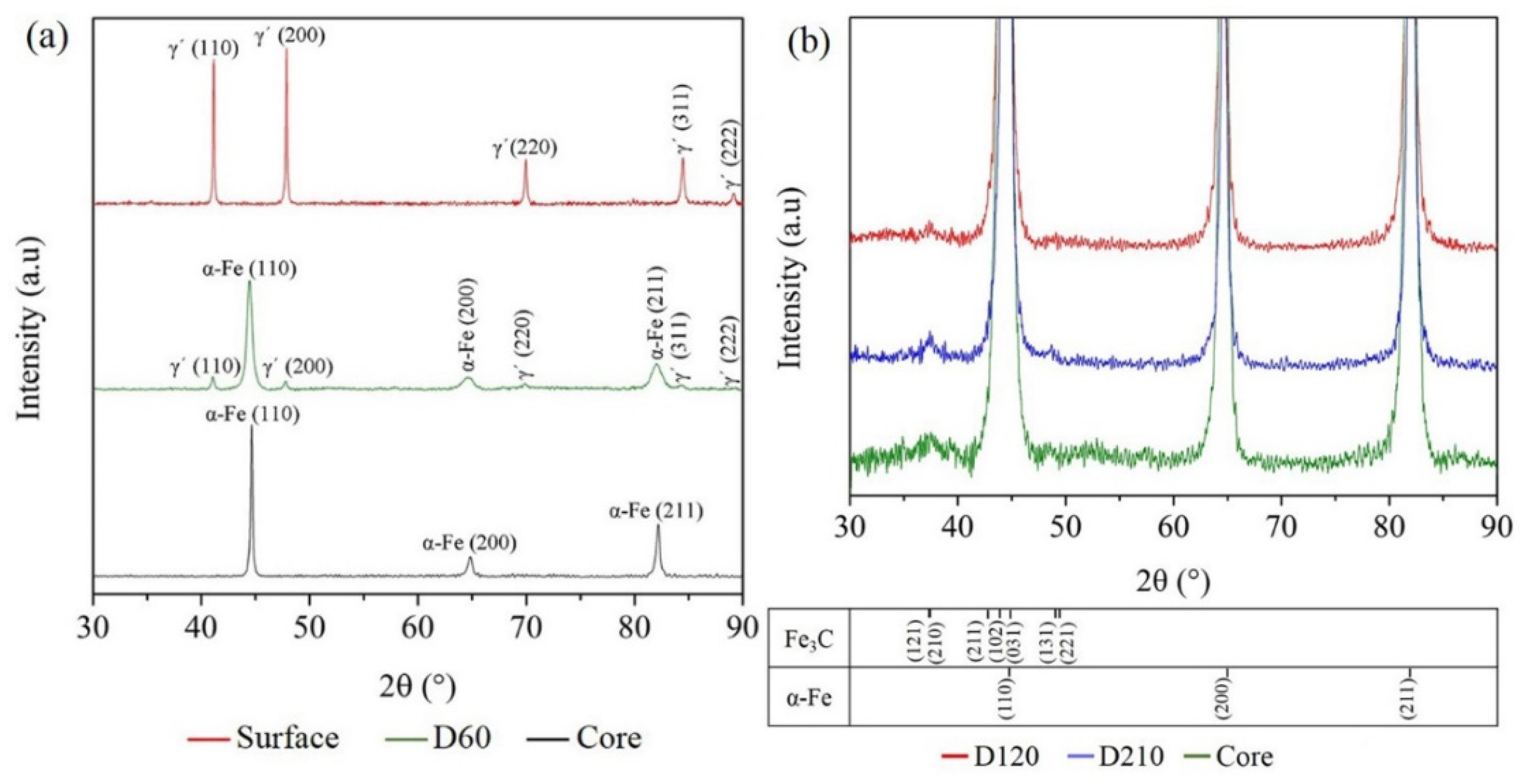
3.3. XRD Results
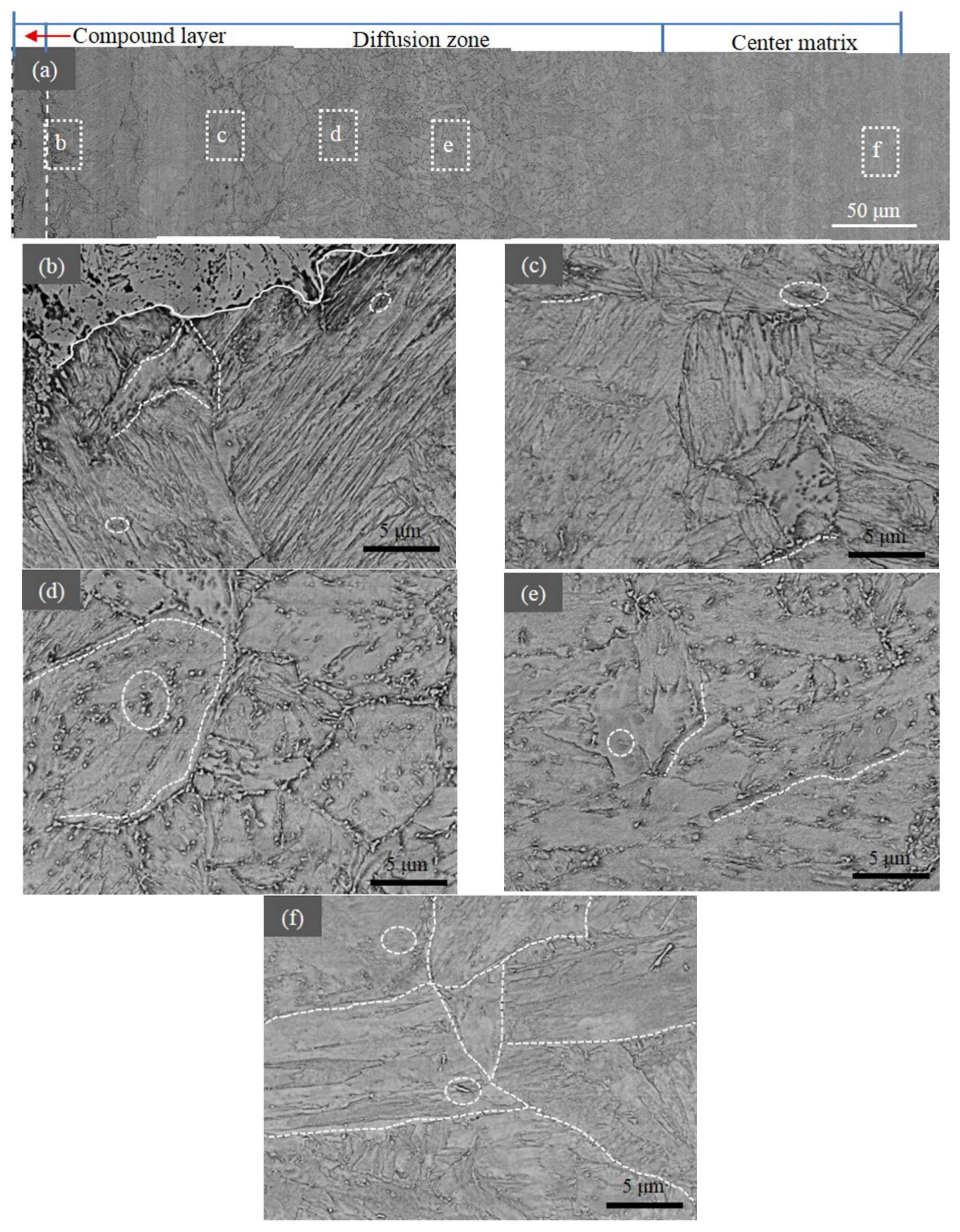
3.4. SEM Results
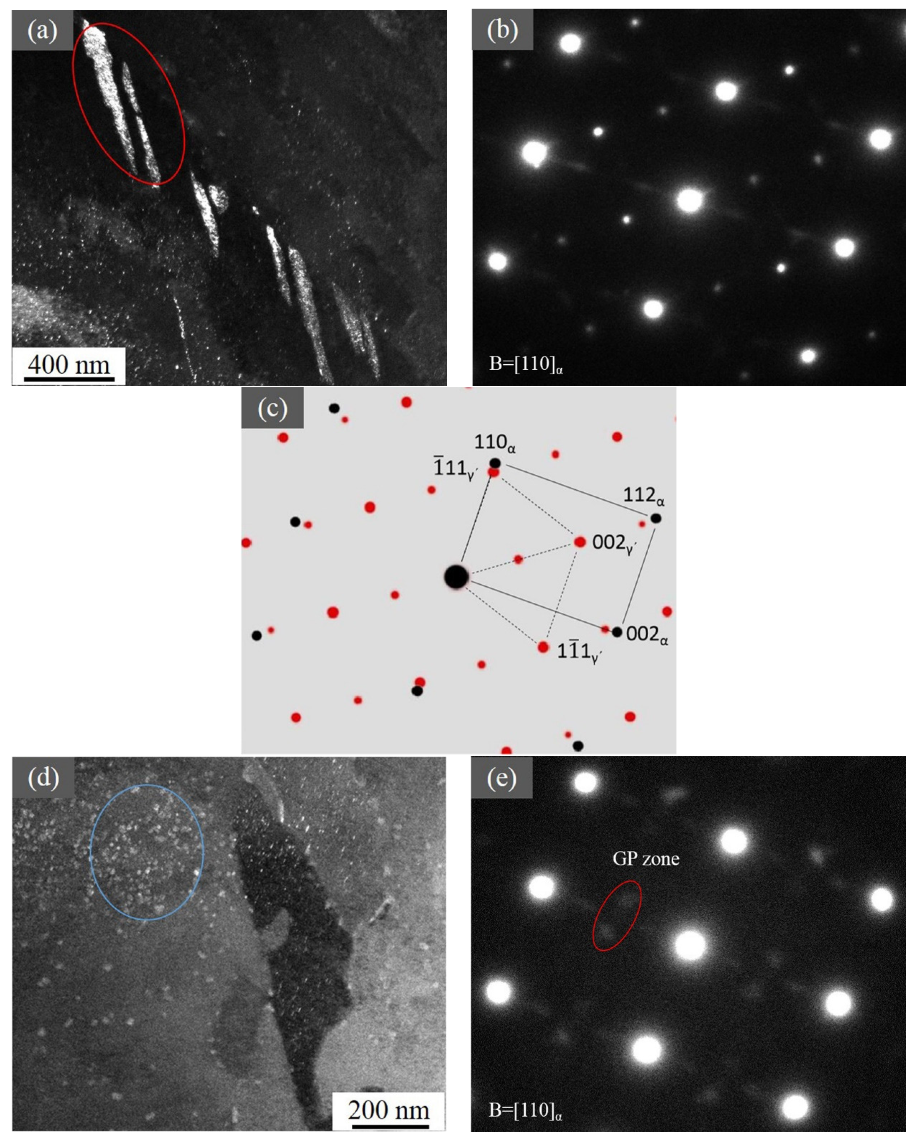
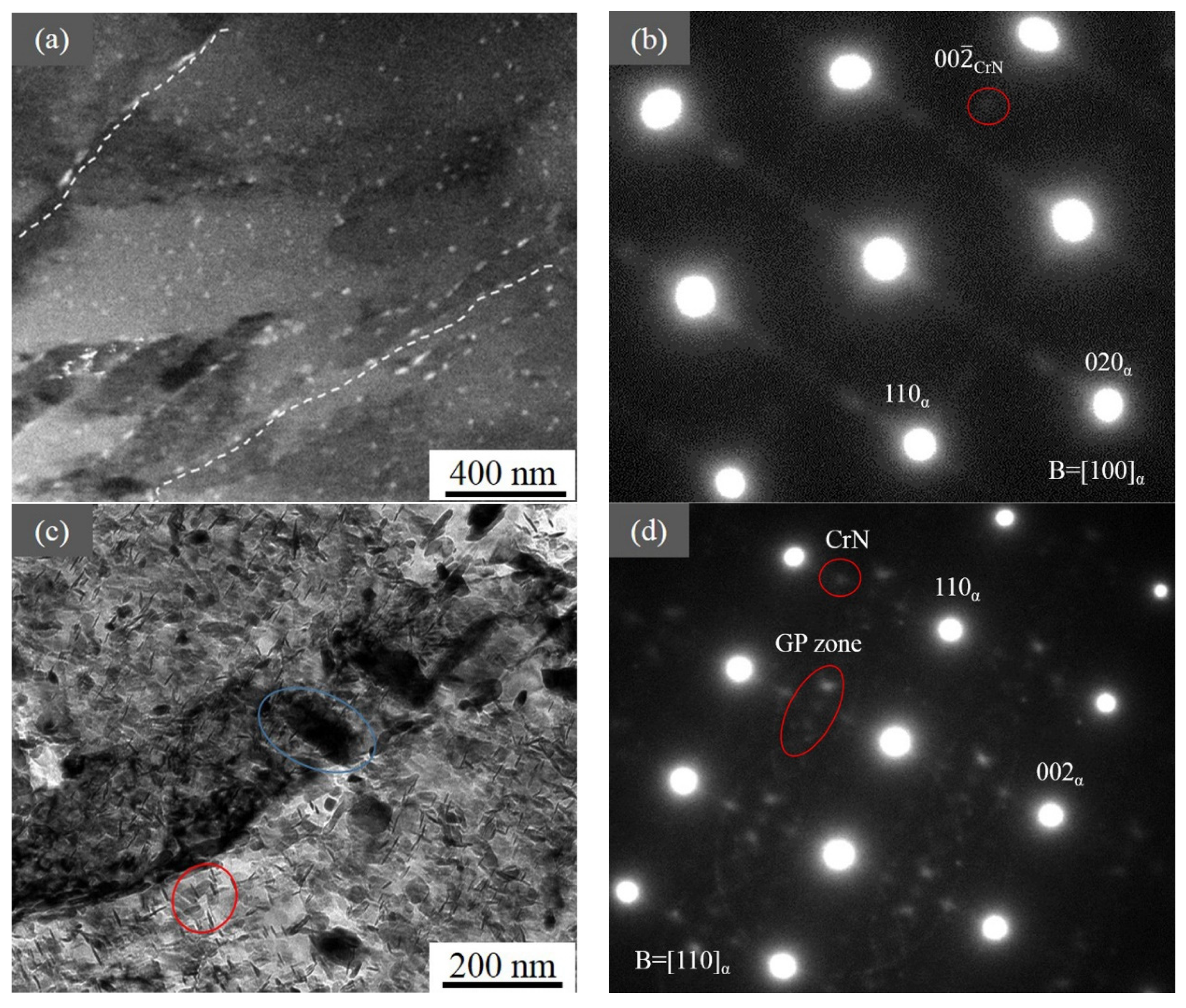
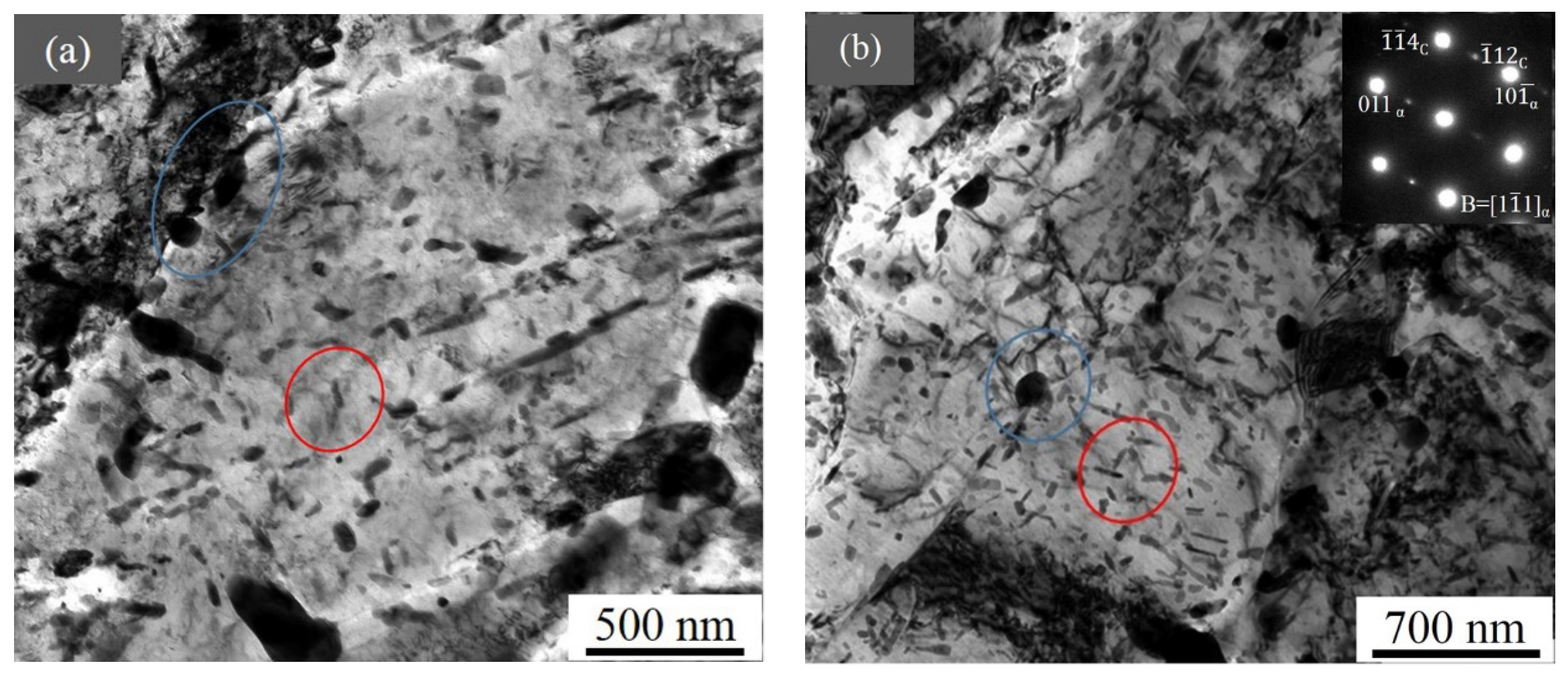
3.5. TEM Results
4. Discussions
4.1. Precipitate Along the Depth
4.2. Influence of Microstructure on Hardness
4.3. Case Hardening
5. Conclusions
Author Contributions
Funding
Acknowledgments
Conflicts of Interest
References
- Akinci, I.; Yilmaz, D.; Canakci, M. Failure of a rotary tiller spur gear. Eng. Fail. Anal. 2005, 12, 400–404. [Google Scholar] [CrossRef]
- Barszcz, T.; Randall, R.B. Application of spectral kurtosis for detection of a tooth crack in the planetary gear of a wind turbine. Mech. Syst. Signal Process. 2009, 23, 1352–1365. [Google Scholar] [CrossRef]
- Fernades, P.J.L. Tooth bending fatigue failures in gears. Eng. Fail. Anal. 1996, 3, 219–225. [Google Scholar] [CrossRef]
- Fernades, P.J.L.; McDuling, C. Surface contact fatigue in gears. Eng. Fail. Anal. 1997, 4, 99–107. [Google Scholar] [CrossRef]
- Prabhu Sekar, R.; Sathishkumar, R. Enhancement of wear resistance on normal contact ratio spur gear pairs through non-standard gears. Wear 2017, 380-381, 228–239. [Google Scholar] [CrossRef]
- Baydar, N.; Balla, A. A comparative study of acoustic and vibration signals in detection of gear failures using Wigner-Ville distribution. Mech. Syst. Signal Process. 2001, 15, 1091–1107. [Google Scholar] [CrossRef]
- Lu, K.; Lu, J. Nanostructured surface layer on metallic materials induced by surface mechanical attrition treatment. Mater. Sci. Eng. A 2004, 375–377, 38–45. [Google Scholar] [CrossRef]
- Hassani-Gangaraj, S.M.; Moridi, A.; Guagliano, M.; Ghidini, A. Nitriding duration reduction without sacrificing mechanical characteristics and fatigue behavior: The beneficial effect of surface nano-crystallization by prior severe shot peening. Mater. Des. 2014, 55, 492–498. [Google Scholar] [CrossRef]
- Hernandez, M.; Staia, M.H.; Puchi-Cabrera, E.S. Evaluation of microstructure and mechanical properties of nitrided steels. Surf. Coat. Technol. 2008, 202, 1935–1943. [Google Scholar] [CrossRef]
- Almeidaa, E.A.D.S.D.; Milana, J.C.G.; Costa, C.E.D. Acquired properties comparison of solid nitriding, gas nitriding and plasma nitriding in tool steels. Mater. Res. 2015, 18, 27–35. [Google Scholar]
- Genel, K.; Demirkol, M. Effect of case depth on fatigue performance of AISI 8620 carburized steel. Int. J. Fatigue 1999, 21, 207–212. [Google Scholar] [CrossRef]
- Kim, H.J.; Kweon, Y.G. High cycle fatigue behavior of gas-carburized medium carbon Cr-Mo steel. Metall. Mater. Trans. A 1996, 27A, 2557–2564. [Google Scholar] [CrossRef]
- Benedetti, M.; Fontanari, V.; Höhn, B.-R.; Oster, P.; Tobie, T. Influence of shot peening on bending tooth fatigue limit of case hardened gears. Int. J. Fatigue 2002, 24, 1127–1136. [Google Scholar] [CrossRef]
- Bagherifard, S.; Fernandez-Pariente, I.; Ghelichi, R.; Guagliano, M. Effect of severe shot peening on microstructure and fatigue strength of cast iron. Int. J. Fatigue 2014, 65, 64–70. [Google Scholar] [CrossRef]
- Wolf, G. New approaches to nitriding. Gear Technol. 1997, 34, 63–65. [Google Scholar]
- Lamont, R.; Craven, A.B. The advantages of ion nitriding gears. Gear Technol. 1996, 13, 18–19. [Google Scholar]
- Díaz, N.E.V.; Hosmani, S.S.; Schacherl, R.E.; Mittemeijer, E.J. Nitride precipitation and coarsening in Fe–2.23 at.% V alloys: XRD and (HR)TEM study of coherent and incoherent diffraction effects caused by misfitting nitride precipitates in a ferrite matrix. Acta Mater. 2008, 56, 4137–4149. [Google Scholar] [CrossRef]
- Jegou, S.; Barrallier, L.; Kubler, R. Phase transformations and induced volume changes in a nitride ternary Fe–3%Cr–0.345%C alloy. Acta Mater. 2010, 58, 2666–2676. [Google Scholar] [CrossRef]
- Kurz, S.J.B.; Meka, S.R.; Schell, N.; Ecker, W.; Keckesd, J.; Mittemeijera, E.J. Residual stress and microstructure depth gradients in nitrided iron-based alloys revealed by dynamical cross-sectional transmission X-ray microdiffraction. Acta Mater. 2015, 87, 100–110. [Google Scholar] [CrossRef]
- Arabczyk, W.; Zamłynny, J. Study of the ammonia decomposition over iron catalysts. Catal. Lett. 1999, 60, 167–171. [Google Scholar] [CrossRef]
- Yang, C.H. Statistical mechanical study on the Freundlich isotherm equation. J. Colloid Interface Sci. 1998, 208, 379–387. [Google Scholar] [CrossRef] [PubMed]
- Wang, B.; Lv, Z.Q.; Zhou, Z.A.; Sun, S.H.; Huang, X.; Fu, W.T. Combined effect of rapid nitriding and plastic deformation on the surface strength, toughness and wear resistance of steel 38CrMoAlA. In IOP Conference Series: Materials Science and Engineering; IOP Publishing: Bristol, UK, 2015; Volume 89, p. 012046. [Google Scholar]
- Wang, B.; Sun, S.H.; Guo, M.W.; Jin, G.F.; Zhou, Z.A.; Fu, W.T. Study on pressurized gas nitriding characteristics for steel 38CrMoAlA. Surf. Coat. Technol. 2015, 279, 60–64. [Google Scholar] [CrossRef]
- Wang, B.; Fu, W.T.; Dong, F.; Jin, G.F.; Feng, W.W.; Wang, Z.H.; Sun, S.H. Significant acceleration of nitriding kinetics in pure iron by pressurized gas treatment. Mater. Des. 2015, 85, 91–96. [Google Scholar] [CrossRef]
- Liu, Z.Q.; Hei, Z.K.; Li, D.X. Microstructural investigation of four kinds of γ′-Fe4N nitrides in ion-nitrided pure iron. J. Mater. Res. 2002, 17, 2621–2627. [Google Scholar] [CrossRef]
- Yang, R.; Wu, G.L.; Zhang, X.; Fu, W.T.; Huang, X. Gradient microstructure and microhardness in a nitrided 18CrNiMo7-6 gear steel. In IOP Conference Series: Materials Science and Engineering; IOP Publishing: Bristol, UK, 2017; Volume 219, p. 012047. [Google Scholar]
- JIS G0562-1993, Method of Measuring Nitrided Case Depth for Iron and Steel; Japanese Industrial Standards: Tokyo, Japan, 1993.
- Morito, S.; Adachi, Y.; Ohba, T. Morphology and crystallography of sub-blocks in ultra-low carbon lath martensite steel. Mater. Trans. JIM 2009, 50, 1919. [Google Scholar] [CrossRef]
- Mittemeijer, E.J.; Somers, M.A.J. Thermodynamics, kinetics, and process control of nitriding. Surf. Eng. 1997, 13, 483–497. [Google Scholar] [CrossRef]
- Mridha, S.; Jack, D.H. Characterization of nitrided 3% chromium steel. Met Sci 1982, 16, 398–404. [Google Scholar] [CrossRef]
- Sun, Y.; Bell, T. Plasma surface engineering of low alloy steel. Mater. Sci. Eng. A 1991, 140, 419–434. [Google Scholar] [CrossRef]
- Hong, Y.; Wu, C.L.; Tian, L.; Li, N.; Xu, Q.; Chen, J.H. Microstructure and property evolution of Fe-N ferrite undergoing early-stages of precipitation. Mater. Sci. Eng. A 2017, 696, 198–204. [Google Scholar] [CrossRef]
- Schwarz, B.; Rossi, P.J.; Straßberger, L.; Jörg, F.; Meka, S.R.; Bischoff, E.; Schacherl, R.E.; Mittemeijer, E.J. Coherency strain and precipitation kinetics: Crystalline and amorphous nitride formation in ternary Fe–Ti/Cr/V–Si alloys. Philos. Mag. 2014, 94, 3098–3104. [Google Scholar] [CrossRef]
- Huang, X.; Pryds, N.H. Crystallography and morphology of cementite precipitates formed during rapid solidification of a ferritic stainless steel. Acta Mater. 2000, 48, 4073–4082. [Google Scholar] [CrossRef]
- Schwarz, B.; Meka, S.R.; Schacherl, R.E.; Bischoff, E.; Mittemeijer, E.J. Nitriding of iron-based ternary Fe–V–Si alloy: The precipitation process of separate nitrides. Acta Mater. 2014, 76, 394–403. [Google Scholar] [CrossRef]
- Howes, M. The Effect of Metallurgy on the Performance of Carburized Gears. Gear Technol. 1996, 3, 20–24. [Google Scholar]
- Mandal, P.; Mamun, A.A.; Silva, L.D.; Lalvani, H.; Perez, M.; Muir, L. Impact of various heat treatments on the microstructure evolution and mechanical properties of hot forged 18CrNiMo7-6 steel. In Proceedings of the Conference: Heat Treatment, Columbus, OH, USA, 24–26 October 2017. [Google Scholar]
- Dong, H.W.; Wang, D.Y.; Song, L.F.; Zhao, H.B. Effects of quenching temperature on microstructure and properties of carburized 17Cr2Ni2Mo steel. Heat Treat. Met. 2015, 40, 144–146. [Google Scholar]


| Element | C | Si | Mn | S | Cr | Ni | Mo | H | Fe |
|---|---|---|---|---|---|---|---|---|---|
| 18CrNiMo7-6 | 0.15–0.21 | 0.17–0.35 | 0.50–0.90 | ≤0.015 | 1.50–1.80 | 1.40–1.70 | 0.25–0.35 | ≤2.0 ppm | Balanced |
| Depth (μm) | Type | Size (nm) | Volume Fraction |
|---|---|---|---|
| 40 | GP and CrN | 9 | 0.07 |
| Fe4N | 45 (aspect ratio 7.6) | 0.08 | |
| 120 | GP and CrN | 18 | 0.06 |
| 210 | GP and CrN | 17 | 0.09 |
| Fe3C | 159 | 0.17 | |
| 360 | Fe3C (small) | 28 (aspect ratio 3.1) | 0.14 |
| Fe3C (large) | 161 | 0.13 | |
| 500 | Fe3C (small) | 25 (aspect ratio 2.5) | 0.21 |
| Fe3C (large) | 154 | 0.10 |
© 2019 by the authors. Licensee MDPI, Basel, Switzerland. This article is an open access article distributed under the terms and conditions of the Creative Commons Attribution (CC BY) license (http://creativecommons.org/licenses/by/4.0/).
Share and Cite
Yang, R.; Wu, G.; Zhang, X.; Fu, W.; Hansen, N.; Huang, X. Gradient Microstructure in a Gear Steel Produced by Pressurized Gas Nitriding. Materials 2019, 12, 3797. https://doi.org/10.3390/ma12223797
Yang R, Wu G, Zhang X, Fu W, Hansen N, Huang X. Gradient Microstructure in a Gear Steel Produced by Pressurized Gas Nitriding. Materials. 2019; 12(22):3797. https://doi.org/10.3390/ma12223797
Chicago/Turabian StyleYang, Ran, Guilin Wu, Xiaodan Zhang, Wantang Fu, Niels Hansen, and Xiaoxu Huang. 2019. "Gradient Microstructure in a Gear Steel Produced by Pressurized Gas Nitriding" Materials 12, no. 22: 3797. https://doi.org/10.3390/ma12223797
APA StyleYang, R., Wu, G., Zhang, X., Fu, W., Hansen, N., & Huang, X. (2019). Gradient Microstructure in a Gear Steel Produced by Pressurized Gas Nitriding. Materials, 12(22), 3797. https://doi.org/10.3390/ma12223797