Article

Free Vibration Analysis of Smart Laminated Functionally Graded CNT Reinforced Composite Plates via New Four-Variable Refined Plate Theory

Faculty of Industrial and Civil Engineering, National University of Civil Engineering, Hanoi 100000, Vietnam
*
Author to whom correspondence should be addressed.
Materials 2019, 12(22), 3675; https://doi.org/10.3390/ma12223675
Submission received: 14 September 2019 / Revised: 26 October 2019 / Accepted: 5 November 2019 / Published: 7 November 2019

Abstract

:
This paper presents a new four-variable refined plate theory for free vibration analysis of laminated piezoelectric functionally graded carbon nanotube-reinforced composite plates (PFG-CNTRC). The present theory includes a parabolic distribution of transverse shear strain through the thickness and satisfies zero traction boundary conditions at both free surfaces of the plates. Thus, no shear correction factor is required. The distribution of carbon nanotubes across the thickness of each FG-CNT layer can be functionally graded or uniformly distributed. Additionally, the electric potential in piezoelectric layers is assumed to be quadratically distributed across the thickness. Equations of motion for PFG-CNTRC rectangular plates are derived using both Maxwell’s equation and Hamilton’s principle. Using the Navier technique, natural frequencies of the simply supported hybrid plate with closed circuit and open circuit of electrical boundary conditions are calculated. New parametric studies regarding the effect of the volume fraction, the CNTs distribution, the number of layers, CNT fiber orientation and thickness of the piezoelectric layer on the free vibration response of hybrid plates are performed.

Graphical Abstract

1. Introduction

A novel class of functionally graded materials (FGM) titled functionally graded carbon nanotube-reinforced composite (FG-CNTRC) plates was first introduced by Shen [1]. Shen’s study revealed that the distribution of CNT had a remarkable influence on the mechanical behaviors of the FG-CNTR plates. Since then, static, dynamic, and buckling behaviors of FG-CNTRC structures have been studied and reported in the literature. Alibeigloo and Liew [2] studied the bending response of simply supported FG-CNTRC rectangular plate under thermo–mechanical loads by using the 3D theory of elasticity. Zhu et al. [3] presented a finite element model to study bending and free vibration responses of thin-to-moderately thick FG-CNTRC plates using the first shear deformation plate theory (FSDT). Lei et al. [4] gave the solution for static analysis of laminated FG-CNTRC plates using the element-free kp-Ritz method. Huang et al. [5] analyzed the bending and free vibration characteristics of antisymmetrically laminated FG-CNTRC plates using the FSDT and simple four-variable theory. The static, vibration and buckling responses of FG-CNTRC resting on elastic foundation were investigated by Wattanasakulpong [6] and Nguyen et al. [7]. Additionally, Shen et al. [8] analyzed the buckling and post-buckling behaviors of symmetrically distributed CNT-reinforced composite plate, including thermal effects. Next, Shen et al. [9] examined the buckling loads and post-buckling equilibrium paths of the CNTRC plates assuming properties of CNTs were temperature-dependent. Using a higher-order shear deformation plate theory (HSDT), the nonlinear free vibration behaviors of the FG-CNTRC plates with an elastic foundation in the thermal environment was investigated by Wang and Shen [10]. That study used the perturbation technique to solve the nonlinear equations of motion. Mehar et al. [11] investigated the static response of the FG-CNTRC doubly curved shell panel, in which the geometric nonlinear and thermal dependent properties of the individual constituents were considered. Using FSDT and piston theory in determining the aerodynamic pressure, Asadi et al. [12] analyzed aeroelastic flutter of FG-CNTRC beams under axial compression and supersonic airflow. These authors continue to study the aero-thermoelastic behaviors of supersonic FG-CNTRC plates taking to account thermal effects in [13].
There have been a limited number of studies related to electromechanical coupling analysis of laminated FG-CNTRC plates with surface-embedded or bonded piezoelectric layers. Using the 3D-theory, Alibeigloo investigated the bending behaviors of the piezoelectric FG-CNTRC (PFG-CNTRC) plates under the mechanical uniform load [14], thermal load, and electric field [2]. Rafiee et al. [15] investigated initial geometrical imperfections in the large amplitude dynamic stability of PFG-CNTRC plates under the simultaneous effect of thermal and electrical loadings. Setoodeh et al. [16] studied the free vibration characteristic of PFG-CNTRC spherical panels by differential quadrature method based on the HSDT. Using the Ritz method with Chebyshev polynomials, Kiani [17] analyzed the free vibration of the PFG-CNTRC plates with opened and closed circuits electrical boundary conditions. In Kiani’s research, the electric potential in the piezoelectric layers was assumed to be linearly distributed through the thickness of the plate. Wu et al. [18] presented a buckling analysis of an arbitrarily thick PFG-CNTRC plate subjected to in-plane compressive loads using unified formulation. Nguyen et al. [19] used the extended isogeometric method with non-uniform rational B-spline and the HSDT to investigate the dynamic response of PFG-CNTRC plates. In the study of Selim et al. [20], an element-free IMLS-Ritz model based on Reddy’s HSDT for the active vibration control of PFG-CNTRC plates was presented. Song et al. [21] used velocity feedback and linear quadratic regulator LQR methods to study active vibration control of PFG-CNTRC cylindrical shells with bonded piezoelectric patches. Zhang et al. [22] used a genetic algorithm to study shape control of FG-CNTRC rectangular plates bonded with piezoelectric patches acting as actuators and sensors.
HSDT [23,24,25,26,27,28] is often desirable for the design of composite structures since it yields more accurate results than the CPT (classical plate theory) and the FSDT. However, these HSDTs have computational costs because the equations of motions based on these HSDT are more. Therefore, simple HSDT must be developed. Recently, based on HSDT, Shimpi [29] developed a new plate theory that has only two unknown displacements, in which the transverse shear stress variation across the thickness is parabolic and equals zero on free surfaces. After that, several researchers introduced a class of four-variable refined plate theory by adding two in-plane displacements and separating the transverse displacements into the bending component and shear component. Meiche et al. [30] presented a new four-variable refined plate theory with hyperbolic shape function for buckling and vibration analysis of FGM sandwich plates. Thai and Vo [31] developed a new sinusoidal shear deformation theory to analyze static and dynamic behaviors of FG plates. Then, another sinusoidal shear deformation theory was also presented by Thai and Kim [32] to investigate the bending and free vibration response of FG plates. Daouadji et al. [33] presented the static analysis of FG plates using a new higher-order shear deformation model.
In present work, a new plate theory with four unknown displacements is presented for free vibration analysis of FG-CNTR plates with two piezoelectric layers bonded at the free surfaces. The electric potential in piezoelectric layers is assumed to be quadratic through the thickness. Navier solution is applied to solve the governing equation of simply supported rectangular plates to obtain the frequencies of the smart FG-CNTRC plates with closed and open circuit electrical conditions. The accuracy of the proposed plate theory is indicated by comparing the obtained natural frequencies with existing results in the literature. Several examples are carried out to show the effects of volume fraction and distribution type of CNTs, the number of layers, CNT fiber orientation, and thickness of piezoelectric layers on the natural frequencies of hybrid plates.

2. Laminated PFG-CNTRC Plates

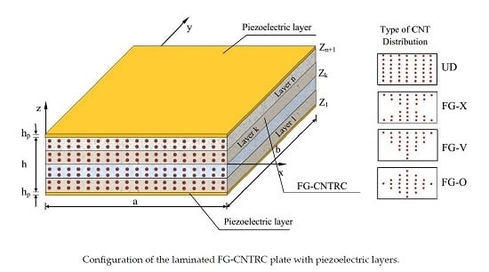
A hybrid laminated FG-CNTRC plate with integrated piezoelectric lamina at top and bottom surfaces is depicted in Figure 1. Width, length, core thickness, and thickness of each piezoelectric layer of the plate are denoted by a and b, h and hp. Four types of CNT distribution across the thickness of each FG-CNT layer namely UD, FG-V, FG-O, and FG-X are also indicated in Figure 1.
The CNT volume fractions for each FG-CNTRC lamina are assumed as follows [3]:
V C N T = V C N T * UD V C N T ( z ) = 1 2 z h V C N T * FG O V C N T ( z ) = 4 z h V C N T * FG X V C N T ( z ) = 1 + 2 z h V C N T * FG V
where:
V C N T * = w C N T w C N T + ρ C N T / ρ m ρ C N T / ρ m w C N T
The effective elastic properties of each FG-CNTRC lamina can be written as follows [3]:
E 11 = η 1 V C N T E 11 C N T + V m E m ;   η 2 E 22 = V C N T E 22 C N T + V m E m ; η 3 G 12 = V C N T G 12 C N T + V m G m ;   v 12 = V C N T * v 12 C N T + V m v m ;   ρ = V C N T ρ C N T + V m ρ m
where E 11 C N T , E 22 C N T , G 12 C N T and E m , G m are Young’s moduli and shear modulus of CNT and isotropic matrix, respectively; η 1 , η 2 , and η 3 are called efficiency parameters. V C N T and V m are the volume fractions of CNT and of matrix, respectively; the Poisson ratio and mass density of CNT/matrix are denoted as v 12 C N T , ρ C N T and v m , ρ m , respectively.
The linear constitutive relations for the FG-CNTRC core can be expressed as
σ x k σ y k τ x y k τ y z k τ x z k = Q ¯ 11 k Q ¯ 12 k 0 0 0 Q ¯ 12 k Q ¯ 22 k 0 0 0 0 0 Q ¯ 66 k 0 0 0 0 0 Q ¯ 44 k 0 0 0 0 0 Q ¯ 55 k ε x ε y γ x y γ y z γ x z
where Q ¯ ij k are the transformed elastic coefficients related to elastic coefficients in material coordinates Q ij [34]:
Q ¯ 11 k = Q 11 k cos 4 θ k + 2 ( Q 12 k + 2 Q 66 k ) sin 2 θ k cos 2 θ k + Q 22 k sin 4 θ k Q ¯ 12 k = ( Q 11 k + Q 22 k 4 Q 66 k ) sin 2 θ k cos 2 θ k + Q 12 k ( sin 4 θ k + cos 4 θ k ) Q ¯ 22 k = Q 11 k sin 4 θ k + 2 ( Q 12 k + 2 Q 66 k ) sin 2 θ k cos 2 θ k + Q 22 k cos 4 θ k Q ¯ 66 k = Q 11 k + Q 22 k 2 ( Q 12 k + Q 66 k ) sin 2 θ k cos 2 θ k + Q 66 k ( sin 4 θ k + cos 4 θ k ) Q ¯ 44 k = Q 44 k cos 2 θ k + Q 55 k sin 2 θ k Q ¯ 55 k = Q 44 k sin 2 θ k + Q 55 k cos 2 θ k
For each the CNT layer:
Q 11 k = E 11 1 ν 12 ν 21 ;   Q 12 k = ν 12 E 22 1 ν 12 ν 21 ;   Q 22 k = E 22 1 ν 12 ν 21 ;   Q 44 k = G 23 k ;   Q 55 k = G 13 k ;   Q 66 k = G 12 k
The constitutive relations for a piezoelectric material can be expressed as [35]
σ x p k σ y p k τ x y p k τ y z p k τ x z p k = C ¯ 11 k C ¯ 12 k 0 0 0 C ¯ 12 k C ¯ 11 k 0 0 0 0 0 1 2 C ¯ 11 k C ¯ 12 k 0 0 0 0 0 C ¯ 55 k 0 0 0 0 0 C ¯ 55 k ε x ε y γ x y γ y z γ x z 0 0 e ¯ 31 k 0 0 e ¯ 31 k 0 0 0 e 15 k 0 0 0 e 15 k 0 E x k E y k E z k
D x k D y k D z k = 0 0 0 e 15 k 0 0 0 0 0 e 15 k e ¯ 31 k e ¯ 31 k 0 0 0 ε x ε y γ x y γ x z γ y z + p 11 k 0 0 0 p 11 k 0 0 0 p ¯ 33 k E x k E y k E z k
The elastic constants for the piezoelectric layer:
C ¯ 11 k = C 11 k C 13 k 2 C 33 k ;   C ¯ 12 k = C 12 k C 13 k 2 C 33 k ;   C ¯ 55 k = C 55 k ;   e ¯ 31 k = e 31 k C 13 k C 33 k e 33 k ;   p ¯ 33 k = p 33 k + e 33 2 k C 33 k
where [ C ij k ] is the elastic constants matrix of the piezoelectric lamina, [ p ij k ] is the dielectric permittivity matrix, [ e ij k ] is the electromechanical coupling matrix, { D k } is the electrical displacement, and { E k } is the electric field in the piezoelectric lamina.

3. Kinematic Equations

According to the four-variable refined plate theory [30,31,32,33], the displacement components at an arbitrary point in the hybrid panel can be expressed as follows:
u ¯ x , y , z , t = u ( x , y , t ) z w b x f z w s x ; v ¯ x , y , z , t = v ( x , y , t ) z w b y f z w s y ; w ¯ x , y , z , t = w b ( x , y , t ) + w s ( x , y , t )
where u ,   v are the displacements of the corresponding point on the reference surface of the plate along x and y axis, respectively; w b and w s are the bending and shear components of the transverse displacement, respectively; the shape function f z represents the distribution of the transverse shear stresses and strains along the thickness.
By supposing the shape function f z satisfies the free transverse shear stress conditions on the free surfaces of the plates, a class of refined plate theory was developed by various researchers as shown in Table 1:
In this study, a new shape function f z is supposed as follows:
f z = z 1 8 + 3 2 z h 2
The linear strain-displacement relations are written as:
ε x = u x z 2 w b x 2 f ( z ) 2 w s x 2 ; ε y = v y z 2 w b y 2 f ( z ) 2 w s y 2 ; ε x y = u y + v x 2 z 2 w b x y 2 f ( z ) 2 w s x y ; γ y z = 1 f ( z ) w s y ; γ x z = 1 f ( z ) w s x
The variation of electric potential through the thickness of the piezoelectric lamina was proposed by Wu et al. [36]:
Φ t ( x , y , z , t ) = ϕ t ( x , y , t ) 1 z h / 2 h p / 2 h p / 2 2 + f ¯ 1 ( x , y , t ) z + f ¯ 2 ( x , y , t )   h / 2   z   h / 2   +   h p Φ b ( x , y , z , t ) = ϕ b ( x , y , t ) 1 z h / 2 h p / 2 h p / 2 2 + f ¯ 3 ( x , y , t ) z + f ¯ 4 ( x , y , t ) h / 2 h p   z   h / 2
where the unknowns f ¯ 1 , f ¯ 2 , f ¯ 3 and f ¯ 4 can be obtained by satisfying the specific electrical boundary condition. In this study, two cases of electrical boundary conditions are considered. For the closed circuit condition, both major surfaces of the piezoelectric lamina are circuited:
Φ ( z = ± h 2 ) = 0 ; Φ ( z = ± ( h 2 + h p ) ) = 0
On the other hand, when one surface is kept at zero voltage and the other is electrically insulated, for the open circuit condition, the electrical boundary conditions are
Φ ( z = ± h 2 ) = 0 ; D z ( z = ± ( h 2 + h p ) ) = 0
In addition, from electric potential function, the electric field can be derived as
E = Φ
Substituting the expressions in Equations (13) and (8) into Equations (14) and (15) yields the electrical potential distribution for the closed circuit (C-circuit) as
Φ t ( x , y , z , t ) = ϕ t ( x , y , t ) 1 z h / 2 h p / 2 h p / 2 2 h / 2   z   h / 2   +   h p Φ b ( x , y , z , t ) = ϕ b ( x , y , t ) 1 z h / 2 h p / 2 h p / 2 2 h / 2 h p   z   h / 2
and for open circuit (O-circuit) as
Φ t ( x , y , z , t ) = ϕ t ( x , y , t ) 1 z h / 2 h p / 2 h p / 2 2 + 4 z h / 2 h p + e ¯ 31 p ¯ 33 u , x + v , y + ( h / 2 + h p ) w b , x x + w b , y y + f ( z ) w s , x x + w s , y y z h / 2 h / 2 z h / 2 + h p Φ b ( x , y , z , t ) = ϕ b ( x , y , t ) 1 z h / 2 h p / 2 h p / 2 2 + 4 z + h / 2 h p + e ¯ 31 p ¯ 33 u , x + v , y ( h / 2 + h p ) w b , x x + w b , y y + f ( z ) w s , x x + w s , y y z + h / 2 h / 2 h p z h / 2

4. Equations of Motion

Hamilton’s principle is used herein to derive the governing differential equations of motion for the free vibration problem. Without external forces, the principle can be stated as [37]
t 1 t 2 δ U δ K d t =   0
in which δU is the variation of the strain energy of the plate and may be expressed as
δ U = A h / 2 h / 2 σ x δ ε x + σ y δ ε y + τ x y δ γ x y + τ x z δ γ x z + τ y z δ γ y z d z d A = A N x δ u x M x b 2 δ w b x 2 M x s 2 δ w s x 2 + N y δ v y M y b 2 δ w b y 2 M y s 2 δ w s y 2 + N x y δ u y + δ v x 2 M x y b 2 δ w b x y 2 M x y s 2 δ w s x y + Q x z δ w s x + Q y z δ w s y d A
where N, M, and Q are stress resultants and defined by
N x , N y , N x y M x b , M y b , M x y b M x s , M y s , M x y s , = k = 1 N h k h k + 1 σ x k , σ y k , τ x y k 1 z f ( z ) d z ;
Q x z s , Q y z s = k = 1 N h k h k + 1 τ x z k , τ y z k g ( z ) d z
and δK is the variation of the kinetic energy of the plate and can be written as follows:
δ K = V u ˙ δ u ˙ + v ˙ δ v ˙ + w ˙ δ w ˙ ρ d A d z = A I ¯ 0 u ˙ δ u ˙ + v ˙ δ v ˙ + ( w ˙ b + w ˙ s ) δ ( w ˙ b + w ˙ s ) I ¯ 1 u ˙ δ w ˙ b x + w ˙ b x δ u ˙ + v ˙ δ w ˙ b y + y δ v ˙ I ¯ 3 u ˙ δ w ˙ s x + w ˙ s x δ u ˙ + v ˙ δ w ˙ s y + w ˙ s y δ v ˙ + I ¯ 2 w ˙ b x δ w ˙ b x + w ˙ b y δ w ˙ b y + I ¯ 5 w ˙ s x δ w ˙ s x + w ˙ s y δ w ˙ s y + I ¯ 4 w ˙ b x δ w ˙ s x + w ˙ s x δ w ˙ b x + w ˙ b y δ w ˙ s y + w ˙ s y δ w ˙ b y d A
where mass moments I 0 , I 1 , I 2 , I 3 , I 4 , I 5 are defined by
I 0 , I 1 , I 2 , I 3 , I 4 , I 5 = k = 1 n h k h k + 1 1 , z , z 2 , f ( z ) , z f ( z ) , f 2 ( z ) ρ ( k ) d z
Substituting Equation (12) into Equation (7), then the obtained results into Equation (21), and combine with the relations in Equation (16), the stress resultants are obtained as follows:
N M b M s = A B B s B D D s B s D s H s ε κ b κ s + N p M b p M s p ;   Q = A s γ + Q p
where
N = N x N y N x y ;   M b = M x b M y b M x y b ;   M s = M x s M y s M x y s ;   Q = Q y z Q x z
N p = N x p N y p N x y p ;   M b p = M x b p M y b p M x y b p ;   M s p = M x s p M y s p M x y s p ;   Q p = Q y z p Q x z p
ε = u x , v y , u y + v x T ;   κ b = 2 w b x 2 ; 2 w b y 2 ; 2 2 w b x y T ;   κ s = 2 w s x 2 ; 2 w s y 2 ; 2 2 w s x y T ;   γ = w s x , w s y T
A = A 11 A 12 A 16 A 12 A 22 A 26 A 16 A 26 A 66 ;   B = B 11 B 12 B 16 B 12 B 22 B 26 B 16 B 26 B 66 ;   D = D 11 D 12 D 16 D 12 D 22 D 26 D 16 D 26 D 66
B s = B 11 s B 12 s B 16 s B 12 s B 22 s B 26 s B 16 s B 26 s B 66 s ; D s = D 11 s D 12 s D 16 s D 12 s D 22 s D 26 s D 16 s D 26 s D 66 s ; H s = H 11 s H 12 s H 16 s H 12 s H 22 s H 26 s H 16 s H 26 s H 66 s ; A s = A 44 s A 45 s A 54 s A 55 s
in which
( A i j , B i j , D i j , B i j s , D i j s , H i j s ) = k = 1 N h k h k + 1 ( 1 , z , z 2 , f ( z ) , z f ( z ) , ( f ( z ) ) 2 ) ( Q ¯ i j ) k d z ( i , j = 1 , 2 , 6 ) A i j s = k = 1 N h k h k + 1 1 f ( z ) 2 ( Q ¯ i j ) k d z ( i , j = 4 , 5 )
and
N x p N y p N x y p , M x p b M y p b M x y p b , M x p s M y p s M x y p s = k = 1 n h k h k + 1 σ x p σ y p τ x y p k 1 ,   z ,   f ( z ) d z Q y z p Q x z p = k = 1 n h k h k + 1 τ y z p τ x z p k 1 f ( z ) d z ;
Substituting the expressions of δU and δK from Equations (21)–(26) into Equation (20) and after some mathematical manipulations, we obtain the equations of motion of the plate as follow:
δ u : N x x + N x y y = I ¯ 0 u ¨ I ¯ 1 w . . b x I ¯ 3 w . . s x δ v : N y y + N x y x = I ¯ 0 v ¨ I ¯ 1 w . . b y I ¯ 3 w . . s y δ w b : 2 M x b x 2 + 2 2 M x y b x y + 2 M y b y 2 = I ¯ 0 ( w . . b + w . . s ) + I ¯ 1 ( u ¨ x + u ¨ y ) I ¯ 2 2 w . . b I ¯ 4 2 w . . s δ w s : 2 M x s x 2 + 2 2 M x y s x y + 2 M y s y 2 + Q x z s x + Q y z s y = I ¯ 0 ( w . . b + w . . s ) + I ¯ 3 ( u ¨ x + v ¨ y ) I ¯ 4 2 w . . b I ¯ 5 2 w - s
In addition, the electric potential in piezoelectric lamina must satisfy Maxwell’s equation:
h h + h p . D d z + h h p h . D d z = k = 1 n p i e h k h k + 1 D x k x + D y k y + D z k z d z = 0

5. Solution Procedures

In this study, two sets of simply supported boundary conditions (SSSS) are used to develop the Navier solutions for rectangular laminated plates and are shown in Table 2.
To satisfy the above boundary conditions, the following expansion displacements u , v , w b , w s are chosen as in Table 3:
where u m n , v m n , w b m n , w s m n are unknown coefficients to be determined, c = c o s ,   s = s i n , α= mπ/a, β = nπ/b.
In addition, the electrostatic potential can be expanded as follows:
ϕ ( x , y , t ) = n = 1 m = 1 ϕ m n e i ω t s α x s β y
Substituting Equation (35) and the displacements in Table 3 into the equations of motion Equations (33) and (34), one obtains the analytical solution in the following matrix form:
χ 11 χ 12 χ 13 χ 14 χ 15 χ 12 χ 22 χ 23 χ 24 χ 25 χ 13 χ 23 χ 33 χ 34 χ 35 χ 14 χ 24 χ 34 χ 44 χ 45 χ 15 χ 25 χ 35 χ 45 χ 55 - ω 2 ψ 11 ψ 12 ψ 13 ψ 14 ψ 15 ψ 12 ψ 22 ψ 23 ψ 24 ψ 25 ψ 13 ψ 23 ψ 33 ψ 34 ψ 35 ψ 14 ψ 24 ψ 34 ψ 44 ψ 45 ψ 15 ψ 25 ψ 35 ψ 45 ψ 55 u m n v m n w m n b w m n s ϕ m n = 0 0 0 0 0
where the matrix elements of Equation (36) are given in the Appendix A.

6. Results and Discussions

In this section, several numerical results are carried out and discussed to verify the accuracy and efficiency of the proposed theory in free vibration analysis of simply supported laminated piezoelectric rectangular plates. Furthermore, the influence of volume fraction of CNTs, distribution of CNTs, number of the lamina, CNT fiber orientation, and thickness of piezoelectric lamina on the natural frequencies of laminated plates are also investigated in detail.

6.1. Comparison Studies

6.1.1. Example 1

The non-dimensional natural frequencies ω ¯ = ω m n h ρ / G of simply supported isotropic square plate were performed and compared with the existing results in Table 4:
It is worth noting that the results obtained by Srinivas et al. [38] used CPT, FSDT, and exact solutions, whereas the work of Shimpi et al. [29] was implemented using a new FSDT. It is seen that all obtained frequencies are in good agreement with available results.

6.1.2. Example 2

The second comparison study as follows:
The fundamental frequency of a square laminated PFG-CNTRC with piezoelectric lamina was calculated and compared with the results of K. Nguyen-Quang et al. [19] using an isogeometric approach. The plate had length a = b = 0.4 m, thickness h = 0.05a. Two continuous piezoelectric (PZT-5A) lamina of thickness hp = 0.1h were bonded to the top and bottom surfaces of the host. The material elastic properties for the matrix, CNT, and piezoelectric are listed in Table 5.
The CNT efficiency parameters are shown in Table 6.
The comparision results are listed in Table 7.
It can be seen that the present results agree well with those acquired by the isogeometric approach [19] for different volume fractions of CNTs, distribution of CNTs, number of layers, CNT fiber orientation, and electrical condition, which indicates the accuracy and correctness of the present formulation and solution method.

6.2. Parametric Studies

After showing the accuracy of the present model, the following new results for free vibration of laminated FG-CNTRC plates integrated with piezoelectric layers were investigated. The material elastic properties for the matrix, CNT, and piezoelectric material are shown in Table 5 and Table 6.

6.2.1. Effect of FG-CNT Parameters

Natural frequencies of anti-symmetric cross-ply and angle-ply laminated PFG-CNTRC (a = b = 0.4m; a/h = 20) are shown in Table 8 and Table 9, Table 10 and Table 11, respectively. It is observed from these tables that the FG-X plates had the highest value of frequency, whereas the FG-O plates had the lowest one. Therefore, it can be concluded that the type of CNT distribution has a remarkable influence on the stiffness of the plate. In detail, the CNTs distributed close to the upper and lower surfaces of each FG-CNTRC layer were more efficient than those distributed near the mid-plane of each FG-CNTRC layer in increasing the stiffness of the laminated PFG-CNTRC. Table 8 reveals that with the increase in the CNT volume fraction, the natural frequencies of the plates increased accordingly; these results are presented in more detail in Figure 2. Table 8 also shows that at the fixed value of the thickness ratio, the stiffness of the plate increased as the number layer of CNT increased. The effects of the width-to-thickness ratio on the natural frequencies of angle-ply laminated PFG-CNTRC plates are also presented in Table 9. As expected, the frequencies decrease with the increment of a/h. This is because the plates become thinner with the increment of a/h, and as the results, the stiffness of the plate decreased.
Figure 2 shows the fundamental frequencies of anti-symmetric angle-ply [p/(θ/−θ)3/p] laminated PFG-CNTRC plates versus the lamination angle (a = b = 0.4m; a/h = 20). It can be seen that the fundamental frequency increased with the increase in lamination angle θ from 0 to 45, and decreased with θ values from 45 to 90 for all four CNT distribution types and three CNT volume fractions. This is compatible with conclusions in previous studies in the literature. The previous conclusions regarding the CNT distribution type are confirmed. Noted that the plate with FG-X distribution type had the highest frequency, while with FG-O type had the lowest one.

6.2.2. Effect of Electrical Condition

The natural frequency of laminated cross-ply FG-CNTRC plates (a = b = 0.4 m; a/h = 20; V*CNT = 0.28) coupled with closed and open piezoelectric layers are shown in Table 8, Table 9, Table 10 and Table 11 with different inlet parameters: CNT volume fraction, CNT distribution type, number of layers, lamination angle, and width-to-thickness ratio. It is seen from these tables that the frequencies of the plates increased as the electrical boundary conditions changed from the closed circuit to the open circuit. Figure 3, once again, indicates that the FG-CNTRC plates coupled with the open circuit of piezoelectric layers had a greater stiffness than the FG-CNTRC plates coupled with the closed circuit of the piezoelectric layers. This may be because the open circuit converts electric potential to mechanical energy while the closed circuit does not.

6.2.3. Effect of Piezoelectric Layer Thickness

The effect of piezoelectric layer thickness on the natural frequency of hybrid plates (a = b = 0.4 m; FG-X; [p/(−45/45)3/p]) for different CNT volume fraction and width-to-thickness was examined. For this purpose, the natural frequency increment δ between O-circuit and C-circuit electrical conditions is defined as:
δ = ω O c i r c u i t ω C c i r c u i t ω C c i r c u i t 100 %
In Figure 4a,b, the effects of piezoelectric layer thickness on the natural frequency increment δ for different CNT volume fractions and different a/h ratio are depicted, respectively. It is found that the natural frequency increment δ had a higher value with a lower volume fraction of CNT and a larger a/h ratio. Furthermore, it can be seen when the hp/h ratio increased, the natural frequency increment δ increased. Accordingly, piezoelectric layer thickness had a greater effect on the natural frequency of an O-circuit piezoelectric coupled plate than that of a C-circuit.
Furthermore, the variations of the frequency parameter ω(Hz) are plotted in Figure 5a,b for the open circuit condition with different CNT volume fractions and different width-to-thickness ratios, respectively. These figures indicate that the natural frequency of the hybrid plate decreased by increasing the thickness of the piezoelectric layer from zeros to a specific value. After this value, the natural frequencies were increased by the incrementing of the piezoelectric layer in the cases of moderately thick plates but seem to be unchanged in cases of thin plates. It can be concluded that the piezoelectric effect is more effective in the case of thick plates rather than thin ones.

7. Conclusions

In summary, this paper shows our contribution to the development of a new four-variable refined plate theory for free vibration analysis of laminated PFG-CNTRC plates. The comparison studies show that the present theory is not only accurate but also efficient in predicting the free vibration responses of the plates.
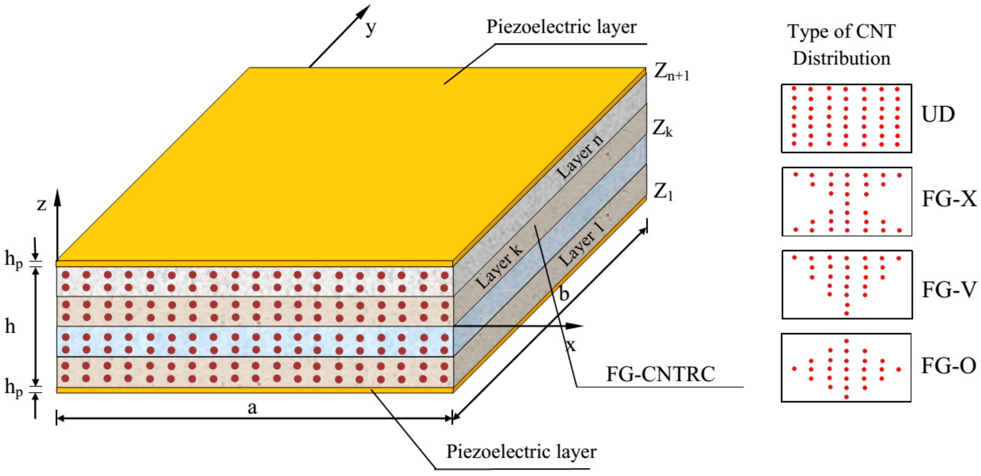
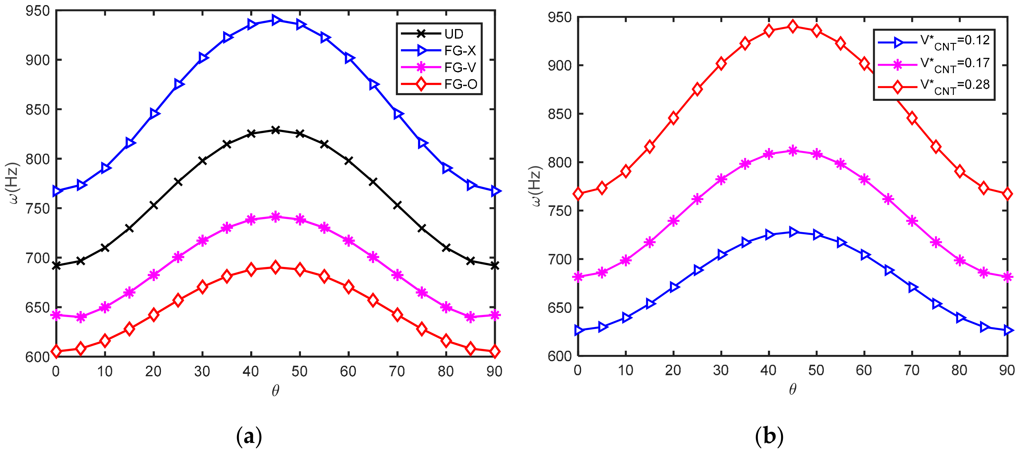
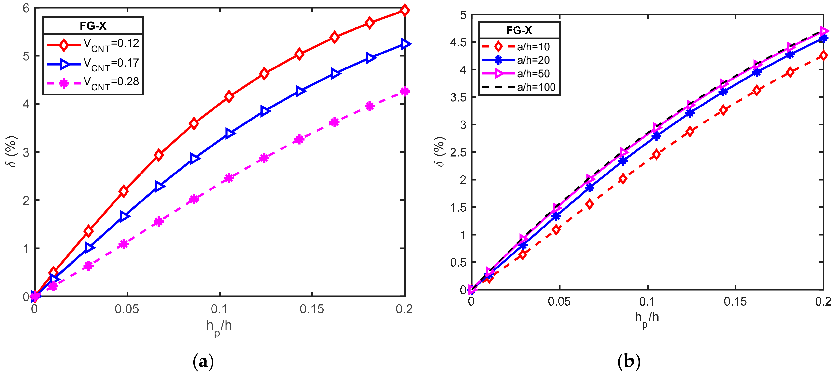
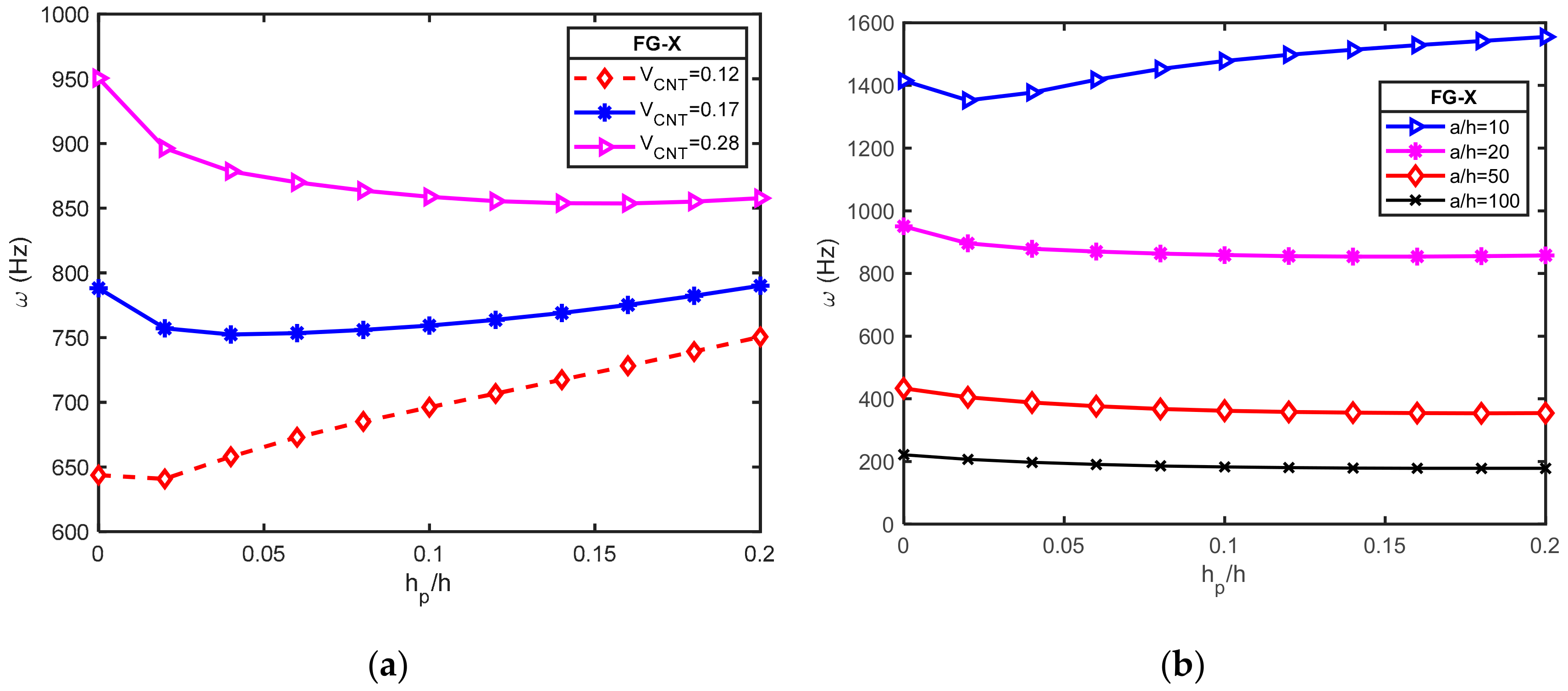
Our insight indicates that the natural frequency of the hybrid plates is strongly affected by the volume fraction of CNT and the distribution type of CNT in the matrix. FG-X CNTRC plate had the highest frequency, while the FG-O CNTRC plate had the smallest frequency regarding all inlet studied parameters. In addition, the lamination angles of CNT fiber and number of CNT lamina have a significant effect on the stiffness of the hybrid plate. Numerical results also revealed that the piezoelectric effect was more prominent in plates bonded with O-circuit piezoelectric lamina because, during vibration, the O-circuit converts electric potential to mechanical energy.
The present theory is accurate and efficient in solving free vibration behaviors of laminated FG-CNT reinforced composite plates with the piezoelectric layer and may be useful in the study of similar composite structures.

Author Contributions

Formal analysis, Software, Writing-original draft, T.H.Q.; Investigation, V.V.T.; Supervision-editing, T.M.T.

Funding

This research received no external funding.

Conflicts of Interest

The authors declared no potential conflicts of interest with respect to the research, authorship, and/or publication of this article.

Appendix A

In case of closed circuit:
χ 11 = 2 C ¯ 11 h p α 2 ( C ¯ 11 C ¯ 12 ) h p β 2 A 11 α 2 A 66 β 2 ; χ 12 = ( C ¯ 11 + C ¯ 12 ) α β h p ( A 12 + A 66 ) α β ;
χ 15 = 0 ; [ χ 22 = ( C ¯ 11 C ¯ 12 ) α 2 h p 2 C ¯ 11 β 2 h p A 66 α 2 A 22 β 2 ; χ 25 = 0 ;
χ 33 = D 11 α 4 D 22 β 4 ( 2 D 12 + 4 D 66 ) α 2 β 2 ( 2 / 3 h p 3 + h c h p 2 + 1 / 2 h c 2 h p ) C ¯ 11 α 4 ( 2 / 3 h p 3 1 / 2 h c 2 h p h c h p 2 ) C ¯ 11 β 4 ( 4 / 3 h p 3 + 2 h c h p 2 + h c 2 h p ) C ¯ 11 α 2 β 2 ;
χ 34 = D 11 s α 4 ( 2 D 12 s + 4 D 66 s ) α 2 β 2 D 22 s β 4 ; χ 35 = 4 / 3 e ¯ 31 h p α 2 + 4 / 3 e ¯ 31 h p β 2 ;
χ 44 = 2 C ¯ 11 α 4 f ( z ) 2 h p 4 C ¯ 11 α 2 β 2 f ( z ) 2 h p 2 C ¯ 11 β 4 f ( z ) 2 h p 2 C 55 α 2 g ( z ) h p 2 C 55 β 2 g ( z ) h p H 11 s α 4 2 H 12 s α 2 β 2 H 22 s β 4 4 H 66 s α 2 β 2 A 44 s β 2 A 55 s α 2 ;
χ 45 = 0 ; χ 21 = χ 1 2 ;   χ 31 = χ 1 3 ;   χ 32 = χ 23 ;   χ 41 = χ 14 ;   χ 42 = χ 24 ;   χ 43 = χ 34 ; χ 51 = χ 15 ; χ 52 = χ 25 ; χ 53 = χ 35 ; χ 54 = χ 45 ;
χ 55 = 4 / 3 h p p 11 α 2 + 4 / 3 h p p 22 β 2 + 16 p ¯ 33 h p ;
ψ 11 = ψ 22 = I ¯ 0 ;   ψ 31 = ψ 13 ;   ψ 32 = ψ 23 ;   ψ 33 = I ¯ 0 + I ¯ 2 ( α 2 + β 2 ) ; ψ 34 = I ¯ 0 + I ¯ 4 ( α 2 + β 2 ) ;   ψ 41 = ψ 14 ;   ψ 42 = ψ 24 ;   ψ 43 = ψ 34 ;   ψ 44 = I ¯ 0 + I ¯ 5 ( α 2 + β 2 ) ;   ψ 12 = ψ 21 = ψ 15 = ψ 51 = 0 ; ψ 25 = ψ 52 = ψ 35 = ψ 53 = ψ 45 = ψ 54 = 0
For cross-ply laminates:
χ 13 = B 11 α 3 + ( B 12 + 2 B 66 ) α β 2 ; χ 14 = 2 C ¯ 11 α 3 f ( z ) h p + 2 C ¯ 11 α β 2 f ( z ) h p + B 11 s α 3 + ( B 12 s + 2 B 66 s ) α β 2 ;
χ 23 = B 22 β 3 + ( B 12 + 2 B 66 ) α 2 β ; χ 24 = 2 C ¯ 11 α 2 β f ( z ) h p + 2 C ¯ 11 β 3 f ( z ) h p + B 22 s β 3 + ( B 12 s + 2 B 66 s ) α 2 β ;
ψ 13 = I ¯ 1 α ; ψ 14 = I ¯ 3 α ; ψ 23 = I ¯ 1 β ; ψ 24 = I ¯ 3 β ;
For angle-ply laminates:
χ 13 = 3 B 16 s α 2 β + B 26 β 3 ; χ 14 = 3 B 16 s α 2 β + B 26 s β 3 ; χ 23 = B 16 α 3 + 3 B 26 α β 2 ; χ 24 = B 16 s α 3 + 3 B 26 s α β 2 ;
ψ 13 = ψ 14 = ψ 23 = ψ 24 = 0 ;
In case of Open circuit:
χ 11 = h p ( C ¯ 12 C 11 ) β 2 2 h p ( C 11 + e ¯ 31 2 p 33 ) α 2 A 66 β 2 A 11 α 2 ;
χ 12 = ( A 12 + A 66 ) α β ( C ¯ 11 + C ¯ 12 2 e ¯ 31 2 p ¯ 33 ) α β h p ;
χ 22 = ( C ¯ 12 C ¯ 11 ) α 2 h p ( C ¯ 11 + β 2 e ¯ 31 2 p ¯ 33 ) 2 h p β 2 A 6 6 α 2 A 22 β 2 ;
χ 33 = D 11 α 4 2 ( D 12 + 2 D 66 ) α 2 β 2 D 22 β 4 2 / 3 C ¯ 11 h p 3 + e ¯ 31 2 h p 3 p ¯ 33 + C ¯ 11 h c h p 2 + 1 / 2 C ¯ 11 h c 2 h p + 3 / 2 e ¯ 31 2 h c h p 2 p ¯ 33 + 1 / 2 e ¯ 31 2 h c 2 h p p ¯ 33 α 4 4 / 3 C ¯ 11 h p 3 + 2 e ¯ 31 2 h p 3 p ¯ 33 + 2 C ¯ 11 h c h p 2 + C ¯ 11 h c 2 h p + 3 e ¯ 31 2 h c h p 2 p ¯ 33 + e ¯ 31 2 h c 2 h p p ¯ 33 α 2 β 2 2 / 3 C ¯ 11 h p 3 + e ¯ 31 2 h p 3 p ¯ 33 + C ¯ 11 h c h p 2 + 1 / 2 C ¯ 11 h c 2 h p + 3 / 2 e ¯ 31 2 h c h p 2 p ¯ 33 + 1 / 2 e ¯ 31 2 h c 2 h p p ¯ 33 β 4 ;
χ 35 = ( e ¯ 31 h c + 4 / 3 e ¯ 31 h p ) 4 α 2 ( e ¯ 31 h c + 4 / 3 e ¯ 31 h p ) 4 β 2 ;
χ 44 = H 11 s α 4 H 22 s β 4 ( H 12 s + 2 H 66 s ) 2 α 2 β 2 A 55 s α 2 + A 44 s β 2 C ¯ 11 + e ¯ 31 2 p ¯ 33 2 f ( z ) 2 h p α 4 C ¯ 11 + e ¯ 31 2 p ¯ 33 2 f ( z ) 2 h p β 4 C ¯ 11 + e ¯ 31 2 p ¯ 33 4 h p f ( z ) 2 α 2 β 2 2 C 55 g ( z ) h p α 2 2 C 55 g ( z ) h p β 2 ;
χ 55 = 16 / 3 h p p 11 α 2 + 16 / 3 h p p 22 β 2 + 16 p ¯ 33 h p ;
For cross-ply laminates:
χ 13 = B 11 α 3 + ( B 12 + 2 B 66 ) α β 2 ;
χ 14 = B 11 s α 3 + B 12 s α β 2 + 2 B 66 s α β 2 + 2 C ¯ 11 α 3 f ( z ) h p + 2 α 3 e ¯ 31 2 f ( z ) h p p ¯ 33 + 2 C ¯ 11 α β 2 f ( z ) h p + 2 α β 2 e ¯ 31 2 f ( z ) h p p ¯ 33 ;
χ 23 = B 22 β 3 + ( B 12 + 2 B 66 ) α 2 β ;
χ 24 = B 22 s β 3 + ( B 12 s + 2 B 66 s ) α 2 β + 2 ( C ¯ 11 + 2 e ¯ 31 2 p ¯ 33 ) β 3 f ( z ) h p + 2 ( C ¯ 11 + e ¯ 31 2 p ¯ 33 ) α 2 β f ( z ) h p ;
For angle-ply laminates:
χ 13 = 3 B 16 s α 2 β + B 26 β 3 ; χ 14 = 3 B 16 s α 2 β + B 26 s β 3 ; χ 23 = B 16 α 3 + 3 B 26 α β 2 ; χ 24 = B 16 s α 3 + 3 B 26 s α β 2 ;
ψ 13 = ψ 14 = ψ 23 = ψ 24 = 0 ;

References

  1. Shen, H.-S. Nonlinear bending of functionally graded carbon nanotube-reinforced composite plates in thermal environments. Compos. Struct. 2009, 91, 9–19. [Google Scholar] [CrossRef]
  2. Alibeigloo, A.; Liew, K. Thermoelastic analysis of functionally graded carbon nanotube-reinforced composite plate using theory of elasticity. Compos. Struct. 2013, 106, 873–881. [Google Scholar] [CrossRef]
  3. Zhu, P.; Lei, Z.; Liew, K.M. Static and free vibration analyses of carbon nanotube-reinforced composite plates using finite element method with first order shear deformation plate theory. Compos. Struct. 2012, 94, 1450–1460. [Google Scholar] [CrossRef]
  4. Lei, Z.; Zhang, L.; Liew, K. Analysis of laminated CNT reinforced functionally graded plates using the element-free kp-Ritz method. Compos. Part B Eng. 2016, 84, 211–221. [Google Scholar] [CrossRef]
  5. Huang, B.; Guo, Y.; Wang, J.; Du, J.; Qian, Z.; Ma, T.; Yi, L. Bending and free vibration analyses of antisymmetrically laminated carbon nanotube-reinforced functionally graded plates. J. Compos. Mater. 2017, 51, 3111–3125. [Google Scholar] [CrossRef]
  6. Wattanasakulpong, N.; Chaikittiratana, A. Exact solutions for static and dynamic analyses of carbon nanotube-reinforced composite plates with Pasternak elastic foundation. Appl. Math. Model. 2015, 39, 5459–5472. [Google Scholar] [CrossRef]
  7. Duc, N.D.; Lee, J.; Nguyen-Thoi, T.; Thang, P.T. Static response and free vibration of functionally graded carbon nanotube-reinforced composite rectangular plates resting on Winkler–Pasternak elastic foundations. Aerosp. Sci. Technol. 2017, 68, 391–402. [Google Scholar] [CrossRef]
  8. Shen, H.-S.; Zhang, C.-L. Thermal buckling and postbuckling behavior of functionally graded carbon nanotube-reinforced composite plates. Mater. Des. 2010, 31, 3403–3411. [Google Scholar] [CrossRef]
  9. Shen, H.-S.; Zhu, Z.H. Buckling and postbuckling behavior of functionally graded nanotube-reinforced composite plates in thermal environments. Comput. Mater. Contin. 2010, 18, 155. [Google Scholar]
  10. Wang, Z.-X.; Shen, H.-S. Nonlinear vibration of nanotube-reinforced composite plates in thermal environments. Comput. Mater. Sci. 2011, 50, 2319–2330. [Google Scholar] [CrossRef]
  11. Mehar, K.; Panda, S.K. Numerical investigation of nonlinear thermomechanical deflection of functionally graded CNT reinforced doubly curved composite shell panel under different mechanical loads. Compos. Struct. 2017, 161, 287–298. [Google Scholar] [CrossRef]
  12. Asadi, H.; Wang, Q. An investigation on the aeroelastic flutter characteristics of FG-CNTRC beams in the supersonic flow. Compos. Part B Eng. 2017, 116, 486–499. [Google Scholar] [CrossRef]
  13. Asadi, H.; Souri, M.; Wang, Q. A numerical study on flow-induced instabilities of supersonic FG-CNT reinforced composite flat panels in thermal environments. Compos. Struct. 2017, 171, 113–125. [Google Scholar] [CrossRef]
  14. Alibeigloo, A. Static analysis of functionally graded carbon nanotube-reinforced composite plate embedded in piezoelectric layers by using theory of elasticity. Compos. Struct. 2013, 95, 612–622. [Google Scholar] [CrossRef]
  15. Rafiee, M.; He, X.; Liew, K. Non-linear dynamic stability of piezoelectric functionally graded carbon nanotube-reinforced composite plates with initial geometric imperfection. Int. J. Non-Linear Mech. 2014, 59, 37–51. [Google Scholar] [CrossRef]
  16. Setoodeh, A.; Shojaee, M.; Malekzadeh, P. Application of transformed differential quadrature to free vibration analysis of FG-CNTRC quadrilateral spherical panel with piezoelectric layers. Comput. Methods Appl. Mech. Eng. 2018, 335, 510–537. [Google Scholar] [CrossRef]
  17. Kiani, Y. Free vibration of functionally graded carbon nanotube reinforced composite plates integrated with piezoelectric layers. Comput. Math. Appl. 2016, 72, 2433–2449. [Google Scholar] [CrossRef]
  18. Wu, C.-P.; Chang, S.-K. Stability of carbon nanotube-reinforced composite plates with surface-bonded piezoelectric layers and under bi-axial compression. Compos. Struct. 2014, 111, 587–601. [Google Scholar] [CrossRef]
  19. Nguyen-Quang, K.; Vo-Duy, T.; Dang-Trung, H.; Nguyen-Thoi, T. An isogeometric approach for dynamic response of laminated FG-CNT reinforced composite plates integrated with piezoelectric layers. Comput. Methods Appl. Mech. Eng. 2018, 332, 25–46. [Google Scholar] [CrossRef]
  20. Selim, B.; Zhang, L.; Liew, K. Active vibration control of CNT-reinforced composite plates with piezoelectric layers based on Reddy’s higher-order shear deformation theory. Compos. Struct. 2017, 163, 350–364. [Google Scholar] [CrossRef]
  21. Song, Z.; Zhang, L.; Liew, K. Active vibration control of CNT-reinforced composite cylindrical shells via piezoelectric patches. Compos. Struct. 2016, 158, 92–100. [Google Scholar] [CrossRef]
  22. Zhang, L.; Song, Z.; Liew, K. Optimal shape control of CNT reinforced functionally graded composite plates using piezoelectric patches. Compos. Part B Eng. 2016, 85, 140–149. [Google Scholar] [CrossRef]
  23. Murty, A.K. Higher order theory for vibrations of thick plates. AIAA J. 1977, 15, 1823–1824. [Google Scholar] [CrossRef]
  24. Lo, K.; Christensen, R.; Wu, E. A high-order theory of plate deformation—Part 1: Homogeneous plates. J. Appl. Mech. 1977, 44, 663–668. [Google Scholar] [CrossRef]
  25. Kant, T. Numerical analysis of thick plates. Comput. Methods Appl. Mech. Eng. 1982, 31, 1–18. [Google Scholar] [CrossRef]
  26. Bhimaraddi, A.; Stevens, L. A higher order theory for free vibration of orthotropic, homogeneous, and laminated rectangular plates. J. Appl. Mech. 1984, 51, 195. [Google Scholar] [CrossRef]
  27. Reddy, J. A refined nonlinear theory of plates with transverse shear deformation. Int. J. Solids Struct. 1984, 20, 881–896. [Google Scholar] [CrossRef]
  28. Hanna, N.; Leissa, A. A higher order shear deformation theory for the vibration of thick plates. J. Sound Vib. 1994, 170, 545–555. [Google Scholar] [CrossRef]
  29. Shimpi, R.; Patel, H. Free vibrations of plate using two variable refined plate theory. J. Sound Vib. 2006, 296, 979–999. [Google Scholar] [CrossRef]
  30. El Meiche, N.; Tounsi, A.; Ziane, N.; Mechab, I. A new hyperbolic shear deformation theory for buckling and vibration of functionally graded sandwich plate. Int. J. Mech. Sci. 2011, 53, 237–247. [Google Scholar] [CrossRef]
  31. Thai, H.-T.; Vo, T.P. A new sinusoidal shear deformation theory for bending, buckling, and vibration of functionally graded plates. Appl. Math. Model. 2013, 37, 3269–3281. [Google Scholar] [CrossRef]
  32. Thai, H.-T.; Kim, S.-E. A simple higher-order shear deformation theory for bending and free vibration analysis of functionally graded plates. Compos. Struct. 2013, 96, 165–173. [Google Scholar] [CrossRef]
  33. Daouadji, T.H.; Tounsi, A. A new higher order shear deformation model for static behavior of functionally graded plates. Adv. Appl. Math. Mech. 2013, 5, 351–364. [Google Scholar] [CrossRef]
  34. Reddy, J.N. Mechanics of Laminated Composite Plates and Shells: Theory and Analysis; CRC Press: Boca Raton, FL, USA, 2004. [Google Scholar]
  35. Farsangi, M.A.; Saidi, A. Levy type solution for free vibration analysis of functionally graded rectangular plates with piezoelectric layers. Smart Mater. Struct. 2012, 21, 094017. [Google Scholar] [CrossRef]
  36. Wu, N.; Wang, Q.; Quek, S. Free vibration analysis of piezoelectric coupled circular plate with open circuit. J. Sound Vib. 2010, 329, 1126–1136. [Google Scholar] [CrossRef]
  37. Reddy, J.N. Energy Principles and Variational Methods in Applied Mechanics; John Wiley & Sons: Hoboken, NJ, USA, 2017. [Google Scholar]
  38. Srinivas, S.; Rao, C.J.; Rao, A. An exact analysis for vibration of simply-supported homogeneous and laminated thick rectangular plates. J. Sound Vib. 1970, 12, 187–199. [Google Scholar] [CrossRef]
Figure 1. Configuration of the laminated piezoelectric functionally graded carbon nanotube-reinforced composite plates (PFG-CNTRC).
Materials 12 03675 g001
Figure 2. Effect of lamination angle on the natural frequency of laminated functionally graded carbon nanotube-reinforced composite plates (FG-CNTRC) plate coupled with O-circuit piezoelectric layer: (a) for different carbon nanotube (CNT) distribution types; (b) for different CNT volume fractions.
Materials 12 03675 g002
Figure 3. Effect of lamination angle on natural frequency of laminated FG-CNTRC plates [p/(−θ/θ)3/p] with electrical condition (a = b = 0.4m; a/h = 20; V*CNT = 0.28): (a) UD; (b) FG-X; (c) FG-V; (d) FG-O.
Materials 12 03675 g003
Figure 4. Variation of the natural frequency increment δ between O-circuit and C-circuit electrical conditions versus the hp/h ratio for a square piezoelectric functionally graded carbon nanotube-reinforced composite plates (PFG-CNTRC) plate (a = b = 0.4 m; FG-X; [p/(−45/45)3/p]): (a) for different CNT volume fractions; (b) for different a/h ratio.
Materials 12 03675 g004
Figure 5. Effect of hp/h ratio on frequency parameter ω   ( Hz ) of a square FG-CNTRC plate coupled with open circuit piezoelectric layer and different width-to-thickness ratio (a = b = 0.4m; V*CNT = 0.28; [p/(−45/45)3/p]): (a) for different CNT volume fractions; (b) for different a/h ratio.
Materials 12 03675 g005
Table 1. Shape functions of several four-variable refined plate theories.
ResearcherShape Function
Shimpi [29] f z = z 1 4 + 5 3 z h 2
N. E Meiche et al. [30] f z = h / π sinh π h z z cosh π / 2 1
Huu-Tai Thai and Thuc P. Vo [31] f z = z h π sin π z h
Huu-Tai Thai and Seung-Eock Kim [32] f z = 4 z 3 3 h 2
Daouadji et al. [33] f z = z z sec h π z 2 h 2 z sec h π 4 1 π 2 tanh π 4
Table 2. Two cases of simply supported boundary condition.
EdgesBoundary Conditions
Cross-Ply Laminates (SS-1)Angle-Ply Laminates (SS-2)
x = 0 and x = a v = w b = w s = 0 ; N x = M x b = M x s =   0 u = w b = w s = 0 ; N x = M x b = M x s = 0
y = 0 and y = b u = w b = w s = 0 ; N y = M y b = M y s =   0 v = w b = w s = 0 ; N y = M y b = M y s = 0
Table 3. The expansion displacements u , v , w b , w s .
DisplacementsBoundary Conditions
SS-1SS-2
u ( x , y , t ) m = 1 n = 1 u m n c α x s β y ;   m = 1 n = 1 u m n s α x c β y ;  
v ( x , y , t ) m = 1 n = 1 v m n s α x c β y ;   m = 1 n = 1 v m n c α x s β y ;  
w b ( x , y , t ) m = 1 n = 1 w m n b s α x s β y ; m = 1 n = 1 w m n b s α x s β y ;  
w s ( x , y , t ) m = 1 n = 1 w m n s s α x s β y ; m = 1 n = 1 w m n s s α x s β y ;
Table 4. Non-dimensional natural frequencies ω ¯ of simply supported boundary conditions (SSSS) isotropic square plate: a / h = 10 ;   b = a .
Mode ω ¯
mnEXACT [38]FSDT [38]CPT [38]Shimpi [29]Present
110.09320.09300.09550.09300.0932
120.22260.22190.23600.22190.2232
220.34210.34060.37320.34060.3435
130.41710.41490.46290.41490.4192
230.52390.52060.59510.52060.5271
14-0.65200.76680.65200.6618
330.68890.68340.80900.68340.6941
240.75110.74460.89260.74470.7572
34-0.88961.09650.88970.9069
150.92680.91741.13650.91740.9356
Table 5. Values of material parameters.
Core PlatePiezoelectric Layer
CNTMatrixPZT-5A
E11CNT = 5.64 TPaEm = (3.52−0.0034T) (GPa)E = 63 GPa; G = 23.3 GPa; ν = 0.35
E22CNT = 7.0800 TPaνm = 0.34ρ = 7750 kg/m3
G12CNT = 1.9455 TPaρm = 1150 kg/m3e31 = −7.209 C/m2, e32 = e31
ν12CNT = 0.175 e33 = 15.118 C/m2
ρCNT = 1400 kg/m3 e15 = e24 = 12.322 C/m2
G23CNT = 1.2 G12CNT p11 = p22 = 1.53 × 10⁻⁸ F/m
p33 = 1.5 × 10⁻⁸ F/m
Table 6. Carbon nanotube (CNT) efficiency parameters with respect to various volume fractions.
V*CNTη1η2η3
0.120.1371.0220.7η2
0.170.1421.6260.7η2
0.280.1411.5850.7η2
Table 7. The fundamental natural frequency (Hz) of the SSSS square piezoelectric laminated piezoelectric functionally graded carbon nanotube-reinforced composite plates (PFG-CNTRC) (a = b = 0.4 m; hp = 0.1h; a/h = 20).
V*CNTTypeElectrical ConditionLaminate Configurations
([p/0/p])[p/0/90/0/p][p/(−45/45/−45)as/p]
PresentRef. [19]PresentRef. [19]PresentRef. [19]
0.12UDC-circuit587.099583.199587.099583.510662.579656.538
-O-circuit621.839627.416621.839627.716692.687695.085
FG-XC-circuit626.536622.009592.695588.372666.224658.696
-O-circuit658.751662.982627.080632.184696.144697.103
FG-VC-circuit563.624560.042585.314581.714661.328655.606
-O-circuit600.128606.518620.273626.205691.506694.272
FG-OC-circuit544.131540.558581.557578.737659.024654.510
-O-circuit581.965588.764616.659623.343689.323693.196
0.17UDC-circuit628.449623.946628.449624.543727.603720.800
-O-circuit660.700665.032660.700665.615754.615755.388
FG-XC-circuit681.622675.814636.195631.317732.516723.781
-O-circuit710.906713.079668.022671.913759.323758.217
FG-VC-circuit595.013591.216625.837621.914726.077719.594
-O-circuit629.510635.182658.370663.359753.169754.324
FG-OC-circuit569.202565.533620.976618.126723.043718.247
-O-circuit605.304611.599653.664659.687750.267752.995
0.28UDC-circuit692.023685.587692.023686.852828.991821.713
-O-circuit720.549721.919720.549723.150851.606850.524
FG-XC-circuit767.318757.950703.736697.260836.338826.415
-O-circuit792.364789.814731.760732.991858.755855.093
FG-VC-circuit642.030637.353688.175682.974827.574820.463
-O-circuit673.463677.399717.082719.788850.294849.465
FG-OC-circuit605.283601.032681.606677.986823.309818.750
-O-circuit638.738643.745710.669714.904846.167847.767
Table 8. The fundamental natural frequency ω(Hz) of anti-symmetric cross-ply [p/(0/90)n/p] laminated PFG-CNTRC plate (a = b = 0.4 m; a/h = 20; hp = 0.1h).
V*cntTypeElectrical ConditionConfiguration
[p/(0/90)1/p][p/(0/90)2/p][p/(0/90)3/p][p/(0/90)5/p]
0.12UDC-circuit535.019574.472581.514585.093
-O-circuit573.531610.057616.623619.965
FG-XC-circuit546.627577.979583.618586.488
-O-circuit584.256613.333618.591621.270
FG-VC-circuit530.609573.512581.131584.998
-O-circuit569.735609.228616.295619.888
FG-OC-circuit523.307571.070579.521583.809
-O-circuit562.746606.888614.765618.768
0.17UDC-circuit554.285610.732620.631625.644
-O-circuit591.418644.038653.340658.059
FG-XC-circuit570.880615.687623.633627.665
-O-circuit606.848648.707656.177659.972
FG-VC-circuit547.378609.367620.155625.610
-O-circuit585.362642.842652.935658.048
FG-OC-circuit537.761606.167618.011623.996
-O-circuit576.130639.756650.882656.515
0.28UDC-circuit575.055664.853680.081687.747
-O-circuit610.417694.753709.197716.482
FG-XC-circuit601.487672.685684.983691.192
-O-circuit635.165702.232713.903719.805
FG-VC-circuit563.213663.041679.760688.157
-O-circuit599.863693.172708.977716.931
FG-OC-circuit549.709658.607676.710685.794
-O-circuit586.877688.865706.029714.662
Table 9. The fundamental natural frequencies ω(Hz) of anti-symmetric angle-ply [p/(−θ/θ)3/p] laminated PFG-CNTRC plate (a = b = 0.4 m; hp = 0.1h; V*CNT = 0.12).
LayersTypeElectrical Conditiona/h
102050100
[p/(−5/5)3/p]UDC-circuit1083.983589.563242.289121.632
-O-circuit1141.716624.136256.978129.043
FG-XC-circuit1087.691591.770243.224122.104
-O-circuit1145.139626.204257.859129.488
FG-VC-circuit1082.852588.833241.972121.472
-O-circuit1140.697623.457256.680128.892
FG-OC-circuit1080.548587.458241.389121.177
-O-circuit1138.576622.171256.131128.615
[p/(−30/30)3/p]UDC-circuit1166.673644.809266.550133.932
-O-circuit1217.212675.925279.922140.691
FG-XC-circuit1172.045648.119267.971134.651
-O-circuit1222.218679.056281.274141.375
FG-VC-circuit1164.971643.678266.053133.680
-O-circuit1215.655674.862279.450140.452
FG-OC-circuit1161.583641.592265.157133.227
-O-circuit1212.503672.890278.598140.021
[p/(−45/45)3/p]UDC-circuit1192.400662.579274.449137.944
-O-circuit1240.859692.687287.437144.514
FG-XC-circuit1198.251666.224276.021138.740
-O-circuit1246.327696.144288.937145.273
FG-VC-circuit1190.536661.328273.896137.664
-O-circuit1239.148691.506286.911144.246
FG-OC-circuit1186.834659.024272.903137.162
-O-circuit1235.694689.323285.965143.767
Table 10. The fundamental natural frequencies ω(Hz) of anti-symmetric angle-ply [p/(−θ/θ)3/p] laminated PFG-CNTRC plate (a = b = 0.4 m; hp = 0.1h; V*CNT = 0.17).
LayersTypeElectrical Conditiona/h
102050100
[p/(−5/5)3/p]UDC-circuit1155.117631.748260.141130.634
O-circuit1208.292663.803273.800137.529
FG-XC-circuit1160.475634.869261.455131.296
O-circuit1213.327666.758275.047138.157
FG-VC-circuit1153.930630.866259.743130.431
O-circuit1207.254662.982273.423137.336
FG-OC-circuit1150.769628.983258.944130.028
O-circuit1204.308661.204272.665136.954
[p/(−30/30)3/p]UDC-circuit1261.941704.587292.376146.997
O-circuit1306.976732.703304.536153.149
FG-XC-circuit1269.356709.089294.304147.971
O-circuit1314.002737.008306.385154.084
FG-VC-circuit1260.134703.205291.744146.674
O-circuit1305.348731.399303.931152.840
FG-OC-circuit1255.663700.434290.549146.070
O-circuit1301.138728.756302.786152.261
[p/(−45/45)3/p]UDC-circuit1294.290727.603302.726152.263
O-circuit1337.071754.615314.466158.209
FG-XC-circuit1302.277732.516304.840153.332
O-circuit1344.658759.323316.500159.237
FG-VC-circuit1292.321726.077302.022151.904
O-circuit1335.288753.169313.791157.863
FG-OC-circuit1287.487723.043300.707151.238
O-circuit1330.721750.267312.527157.223
Table 11. The fundamental natural frequencies ω(Hz) of anti-symmetric angle-ply [p/(−θ/θ)3/p] laminated PFG-CNTRC plate (a = b = 0.4 m; hp = 0.1h; V*CNT = 0.28).
ConfigurationTypeElectrical Conditiona/h
102050100
[p/(−5/5)3/p]UDC-circuit1252.438696.727288.711145.122
O-circuit1298.062725.018300.910151.292
FG-XC-circuit1261.724701.745290.768146.154
O-circuit1307.040729.846302.884152.282
FG-VC-circuit1252.602695.985288.272144.891
O-circuit1298.480724.357300.493151.071
FG-OC-circuit1247.846693.164287.074144.287
O-circuit1293.968721.661299.345150.492
[p/(−30/30)3/p]UDC-circuit1391.451797.939334.643168.530
O-circuit1428.003821.744345.144173.861
FG-XC-circuit1403.564804.759337.484169.959
O-circuit1439.786828.365347.899175.247
FG-VC-circuit1391.475796.657333.881168.128
O-circuit1428.307820.563344.410173.472
FG-OC-circuit1385.151792.713332.170167.262
O-circuit1422.249816.756342.754172.633
[p/(−45/45)3/p]UDC-circuit1431.534828.991349.087175.920
O-circuit1465.742851.606359.140181.030
FG-XC-circuit1444.428836.338352.162177.468
O-circuit1478.305858.755362.130182.535
FG-VC-circuit1431.592827.574348.231175.467
O-circuit1466.081850.294358.314180.591
FG-OC-circuit1424.854823.309346.367174.523
O-circuit1459.610846.167356.505179.673

