Article

Interfacial Bonding and Abrasive Wear Behavior of Iron Matrix Composite Reinforced by Ceramic Particles

1
State Key Laboratory for Mechanical Behavior of Materials, Xi’an Jiaotong University, Xi’an 710049, China
2
Xi’an Microelectronic Technology Institute, Xi’an 710054, China
3
Guangdong Institute of Materials and Processing, Guangzhou 510650, China
4
Yancheng Jiuheng Industry & Trade Co., Ltd., Yancheng 224021, China
*
Author to whom correspondence should be addressed.
Materials 2019, 12(22), 3646; https://doi.org/10.3390/ma12223646
Submission received: 18 October 2019 / Revised: 1 November 2019 / Accepted: 1 November 2019 / Published: 6 November 2019

Abstract

:
Using zirconia toughened alumina (ZTA) particles and Ni–Ti complex powders as raw materials, high-Cr cast iron reinforced by ZTA particles was prepared by an infiltration casting process. A continuous transition layer formed at the interface between ZTA particles and the Cr15 matrix, which proves that there is strong metallurgical interfacial bonding at the interface. The phases in the Ni–Ti layer of the ZTAP/Fe composite were preserved compared with the microstructure of sintered ZTA ceramic preform. The hardness of the Ni3Ti, TiO and AlNi2Ti phases in the interfacial transition layer was measured by the nano-indentation method, which is 12.5 GPa, 16.1 GPa and 9.2 GPa, respectively. The three-body wear resistance of the composite reached 12.6 times that of high-Cr cast iron.

1. Introduction

Hard ceramics have high hardness, advanced temperature stability, desirable stiffness and favorable corrosion resistance, which means they are widely used as cutting tools, wear resistant parts, aircraft components, etc. [1,2,3,4]. In particular, hard ceramics are extensively used as reinforcement for fabrication of particles reinforced iron matrix composites (PRIMCs). PRIMCs are of great industrial importance not only because the iron matrix is inexpensive, but also because the particles demonstrate superior properties of high elastic modulus, superior hardness and wear resistance [5,6,7,8]. PRIMCs are widely used in strong impact or high stress wear conditions, such as a hammer crusher, vertical mill grinding roller and grinding disc.
Among many PRIMCs, ZTAP/Fe composites have become a kind of promising wear resistant material, mainly because of the outstanding thermal physical and mechanical properties of ZTA ceramics [5]. Generally, the physical properties of ZTA varied over a relatively large range by modifying the proportion of ZrO2 for different working demands [9,10,11,12,13]. The difference in thermal expansion coefficient (TEC) between ZTA ceramic (7.8–20 × 10−6 °C−1 [5,14]) and iron matrix (9.2–16.9 × 10⁻⁶ °C−1 [15]) is lower than other hard ceramics, such as WC (3.8 × 10⁻⁶ °C−1 [5]), α-Al2O3 (6.4–7.5 × 10⁻⁶ °C−1 [16]), α-SiO2 (0.5–4.1 × 10⁻⁶ °C−1 [17]) and SiC (4.1–4.6 × 10⁻⁶ °C−1 [18]). The high hardness (12–20 GPa [19,20]) and special self-toughening property of ZTA enable the potential excellent wear resistance of ZTAP/Fe composites under severe wear conditions (e.g., high-stress wear condition, high impact wear condition, etc.).
However, the ZTA is hardly wetted by molten iron, and the mechanical bonding is easily formed at the interface between ZTA and iron; thereby the ceramic particles at the surface of the composite may be stripped under severe wear conditions. In order to improve the interfacial bonding property, Sui et al. [21] prepared a kind of ZTAP/Fe composite by an infiltration casting process; the TiO2 powder and Na2nH2O·SiO2 solution were coated onto ZTA particles, and an interfacial transition layer formed between ZTA particles and iron matrix after casting, which mainly contains amorphous Na4SiO4 phases. In our past work [22], we developed a nickel-plating process to deposit ZTA particles, which benefited the interfacial bonding behavior and therefore the three-body wear resistance. However, the interfacial bonding mechanism is still a mechanical bonding. By employing Ti and Si elements at the Al2O3P/Fe interface, Bahraini et al. [23] prepared a steel-based composite by using different infiltration atmospheres, where the chemical reaction could be observed in the interface. Vasic et al. [24] studied the chemical reaction between molten iron and Al2O3 ceramic plate deposited by Ti elements on the surface, and they found a large number of irregular Fe–Ti alloys formed at the interface between Al2O3 ceramic and iron. Inspired by the above studies, the Ni–Ti powder mixture, designed as an interfacial transition layer, was introduced into the interface of ZTAP/Fe composites in this work. The interfacial bonding characteristic between ZTA and iron was analyzed; the three-body abrasive wear test was performed, and its wear physical mechanism is proposed.

2. Materials and Methods

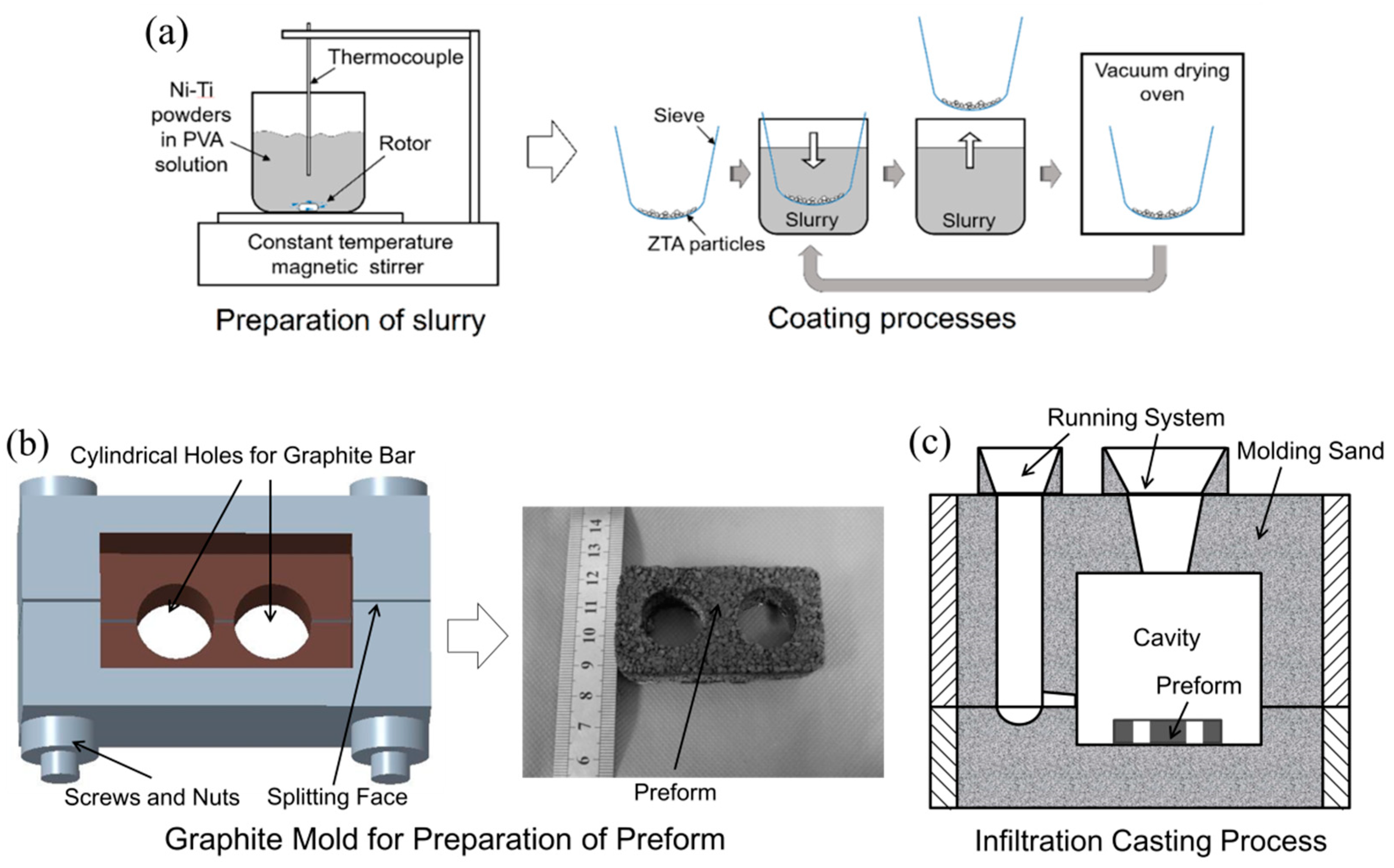
2.1. Preparation of Composite

The ZTA particles (~1 mm in diameter, containing ~80 vol.% ZrO2), were chosen as reinforcement for the high-Cr cast iron matrix composite. An infiltration process, summarized below, produced the ZTAP/Fe composites.
The first step was a slurry coating process, as shown in Figure 1a. This included: (i) Ni and Ti elemental powders (40–50 μm) were totally mixed in ethanol by alumina milling balls for 24 h. (ii) The slurry was prepared by dispersing the Ni–Ti powder mixture homogeneously in polyvinyl alcohol (PVA) solution by a constant-temperature magnetic agitator; PVA solution was feasible as slurry for various powders, such as Ti, Al, Fe, Ni, etc., because powders in PVA solution have excellent dispersibility and good stickiness [25,26,27,28]. (iii) The mesh with ZTA particles inside was dipped into the slurry. (iv) The mesh with ZTA particles inside was taken out of the slurry and dried in a vacuum drying oven at 100 °C. (v) Procedures (iii) and (iv) were repeated several times so that the coatings on the particles could be obtained.
The second step was preparation of the preform, which was prepared from coated ZTA particles by sintering them in a graphite mold with protection from an argon atmosphere. The sintering temperature was chosen as 1500 °C, which was slightly higher than the melting point of Ni (1428 °C). The holding time of sintering was 1 h because the preform can withstand the impact of the molten iron during the subsequent infiltration casting process. Normally, we evaluate the anti-impact of liquid iron by performing a compressive test, and so the compressive strength of the preform was obtained by a universal mechanical testing machine.
Lastly, the composite was prepared by an infiltration casting process as shown in Figure 1b. The preform was located at the bottom of the cavity before pouring the molten Cr15 matrix. The chemical compositions of which were: Cr 15 wt.%, C 3.1–3.2 wt.%, Si 0.5–1.0 wt.%, Mn 0.6–0.7 wt.%, Mo 1.0–1.5 wt.% and balanced Fe. The pouring temperature of the Cr15 matrix was 1550 °C, which was a little higher than common industrial practice (~1420 °C [29]) in order to improve the flowability of the molten iron. The casting composite ingot was shaken out from the sand mold after 12 h to avoid the foundry cracks.

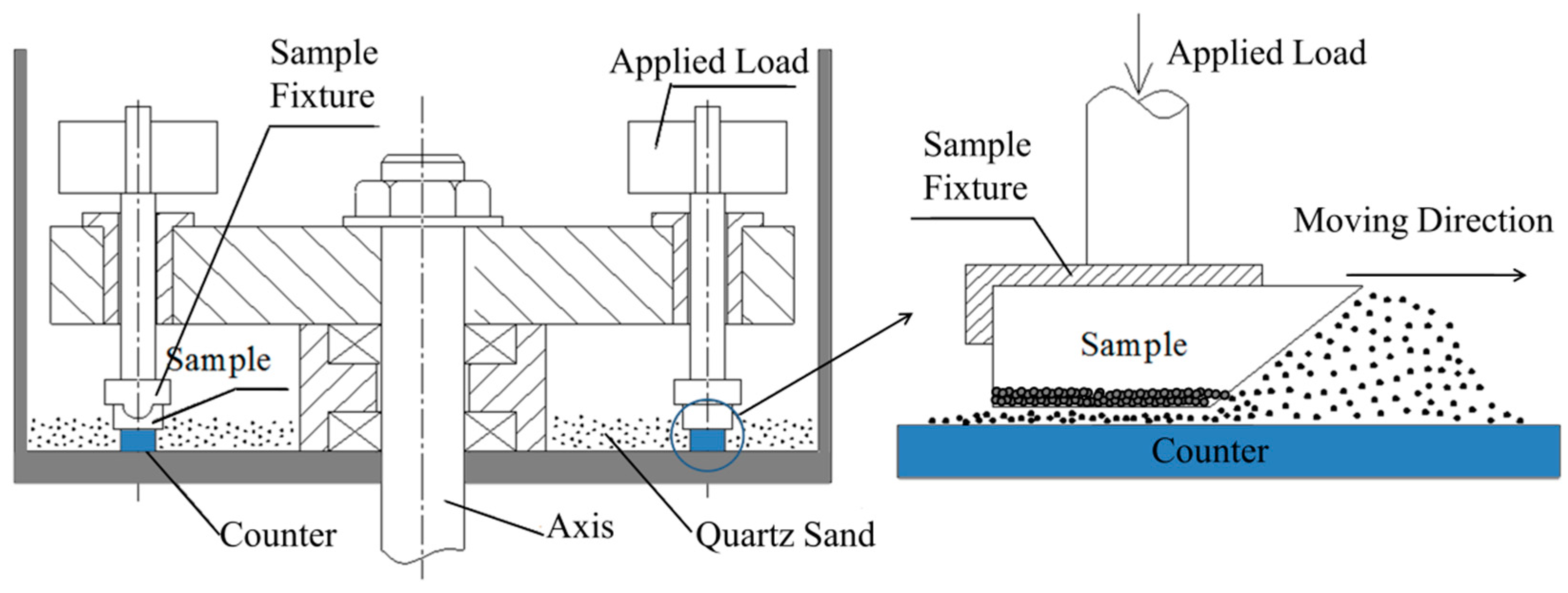
2.2. Three-Body Abrasive Wear Tests

The three-body abrasive wear property of the composite, as well as reference Cr15 specimen, was tested by the MMH-5 block-on-counter abrasive wear tester (Hesion, Jinan, China) (Figure 2). All specimens were cut to a size of 15 × 25 × 6 mm, with a 45° slope forward in order to assist the abrasives to move between the specimens and counter, i.e., the contact area was 15 × 25 mm. The specimens were clamped, as shown in Figure 2, on an annealed AISI1020 steel counter (Hesion, Jinan, China) (~340 mm inside diameter), and were covered by loose SiO2 abrasives with ~150 μm average diameter and 5 kg in weight. The cross sectional dimension of the counter was rectangular (20 × 10 mm). The wear behavior was studied under loads of 1, 2 and 3 kg.
Firstly, a pre-wear process was executed for 60 min with 30 r/min in order to keep the similar surface condition of each specimen. The weight of the specimen (after cleaning in ethanol, similarly hereinafter) was measured and recorded as m0. After that, the three-body wear test was performed for 2.5 h with the same wear velocity. Three repetitions were made for each wear condition. The weight of each specimen was measured every 30 min by using a balance with an accuracy of 10−4 g, and recorded as m1, m2, m3, m4 and m5, respectively. Therefore, the mass loss of each duration Δmi was calculated by Equation (1). The composite layer in the casting ingot consists of two parts, i.e., ZTA ceramic particles and iron matrix, which have different densities. The wear volume loss ΔVi is more effective than mass loss Δmi at characterizing the wear behavior. The wear volume loss ΔVi can be found by using Equation (2).
Δ m i = m i m i 1         ( I =   1 ,   2 ,   ,   5 )
Δ V i = Δ m i α ρ p + ( 1 α ) ρ m
where α refers to the volume fraction of ZTA particles in the composite layer of the casting ingot, given by the image analysis of the composite surfaces; ρp and ρm (in kg·m−3) refer to the densities of ZTA ceramic and Cr15, respectively. At last, in order to have an accurate evaluation, the relative wear resistance was specified by ε (=ΔV0Vi), where ΔV0 denotes the volume loss of reference Cr15 matrix.

3. Results and Discussion

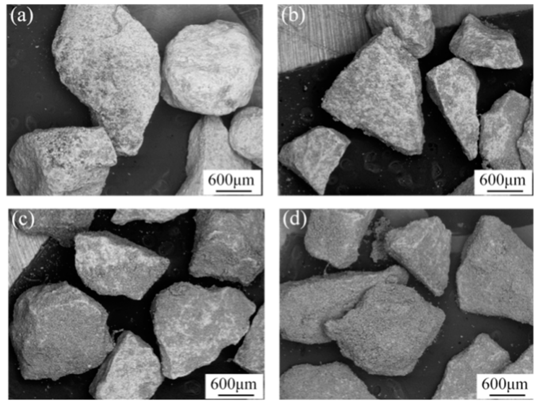
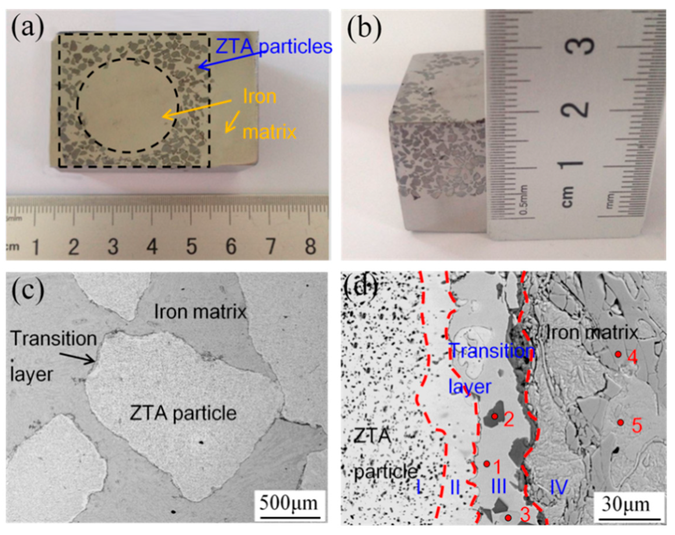
3.1. The Structure of ZTA Ceramic Preforms

Figure 3 shows the surface morphology of coated ZTA particles under different coating times. It can be seen that the coating area of Ni–Ti powders on ZTA particles increased with the coating times, turning from bright to dark; both the weight of coated particles and the thickness of surface coating increased linearly with increasing coating time. After coating 20 times, the ZTA particles were covered by Ni–Ti powder. However, the surface coating was loose and porous, as the PVA solution in slurry was boiled-off in a vacuum drying oven. Thereafter, the coated ZTA particles were sintered under 1500 °C for 1 h. The morphology of sintered ZTA ceramic preform (Figure 4a,b) shows that all particles were connected and formed a porous structure, which will benefit the following cast infiltration process. Meanwhile, it can be seen that a compact sintered coating existed around ZTA ceramic particles and the metallic sintered necks connected the surrounding ZTA ceramics. The magnified image of the surface of sintered ZTA particles is shown in Figure 4c; the sintered shell covered the surface of the ZTA particles. Furthermore, the sintered ceramic particles were pulverized into a powder for X-ray diffraction analysis; the results are shown in Figure 4d, which indicate that the sintered ZTA particles consisted of multiple phases, i.e., ZrO2, Al2O3, Ni3Ti, AlNi2Ti and TiO. Among the above phases, Ni3Ti, AlNi2Ti and TiO were the reaction products between Ni–Ti coating and ZTA particles during sintering.
When sintered at 1500 °C, the nickel melted, which could increase the contact area between the Ni–Ti coating and ZTA particles. The Al atoms in ZTA particles diffused outside and reacted with the Ni–Ti coating, which formed the AlNi2Ti phase, and therefore, an Al-depleted zone was formed surrounding the ZTA particles as shown in Figure 4c. Outside the Al-depleted zone, a compact Ni–Ti layer was formed. For understanding the phase structure around ZTA particles, a semi-quantitative EDS analysis was performed and the results are listed in Table 1. The ZTA particle is on the left side of the dashed line in Figure 4c, and was composed of ZrO2 and Al2O3. In the middle Al-depleted zone, the ZrO2 phase was mainly found. In the right Ni–Ti coating zone, three different phases were detected, including AlNi2Ti (point 2), Ni3Ti (point 3) and TiO (point 4). The main phase in sintered coating is Ni3Ti, which is the most thermodynamically favorable among all Ni–Ti compounds [30]. The outmost ZTA particle preform was covered by TiO film because of the high chemical activity of Ti atoms. At the same time, the compressive strength of the preform was tested and the result was about 4.1 MPa, as the metallurgical bonding between the Ni–Ti coating and ZTA particles could improve the mechanical strength of the sintered ceramic preform.

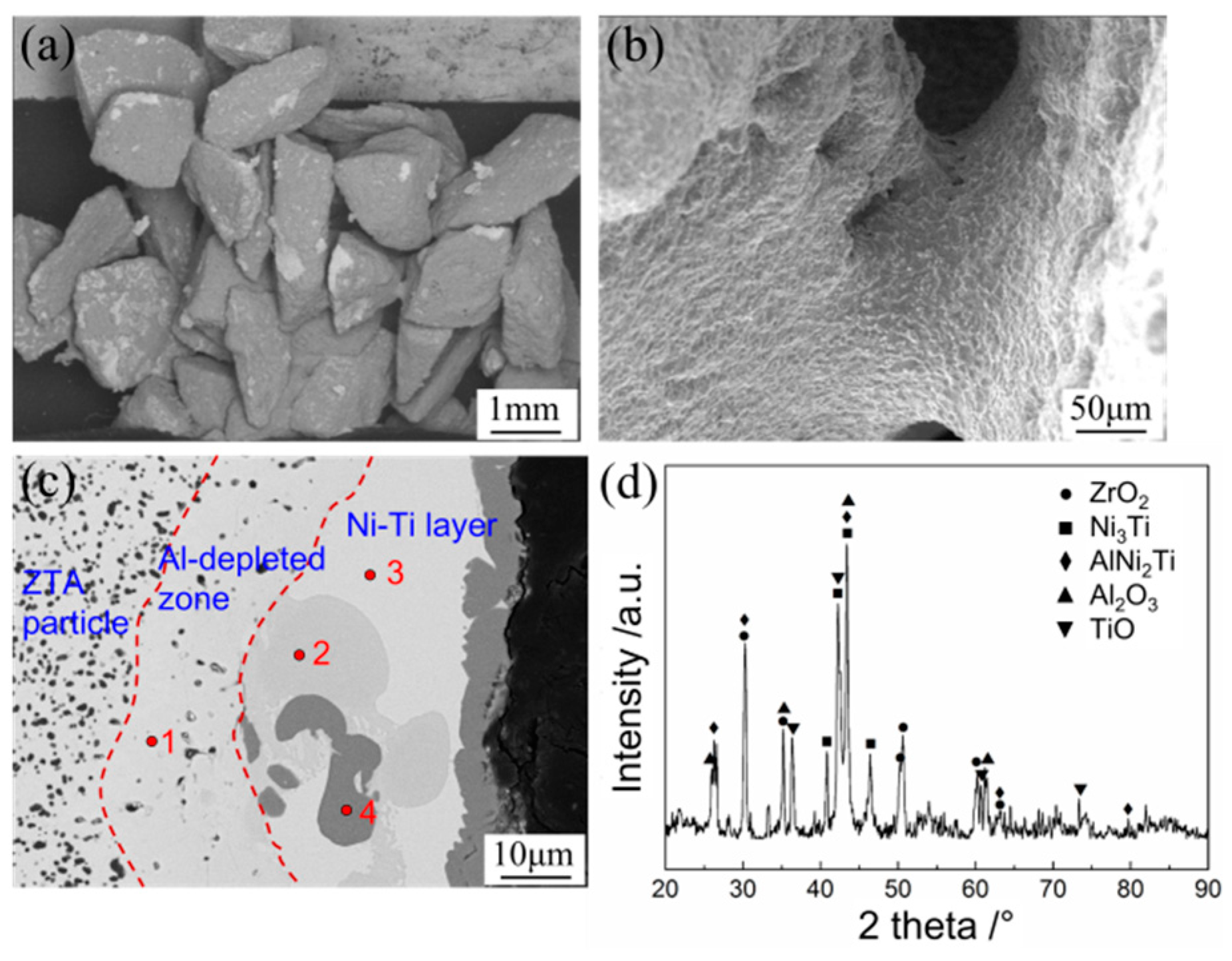
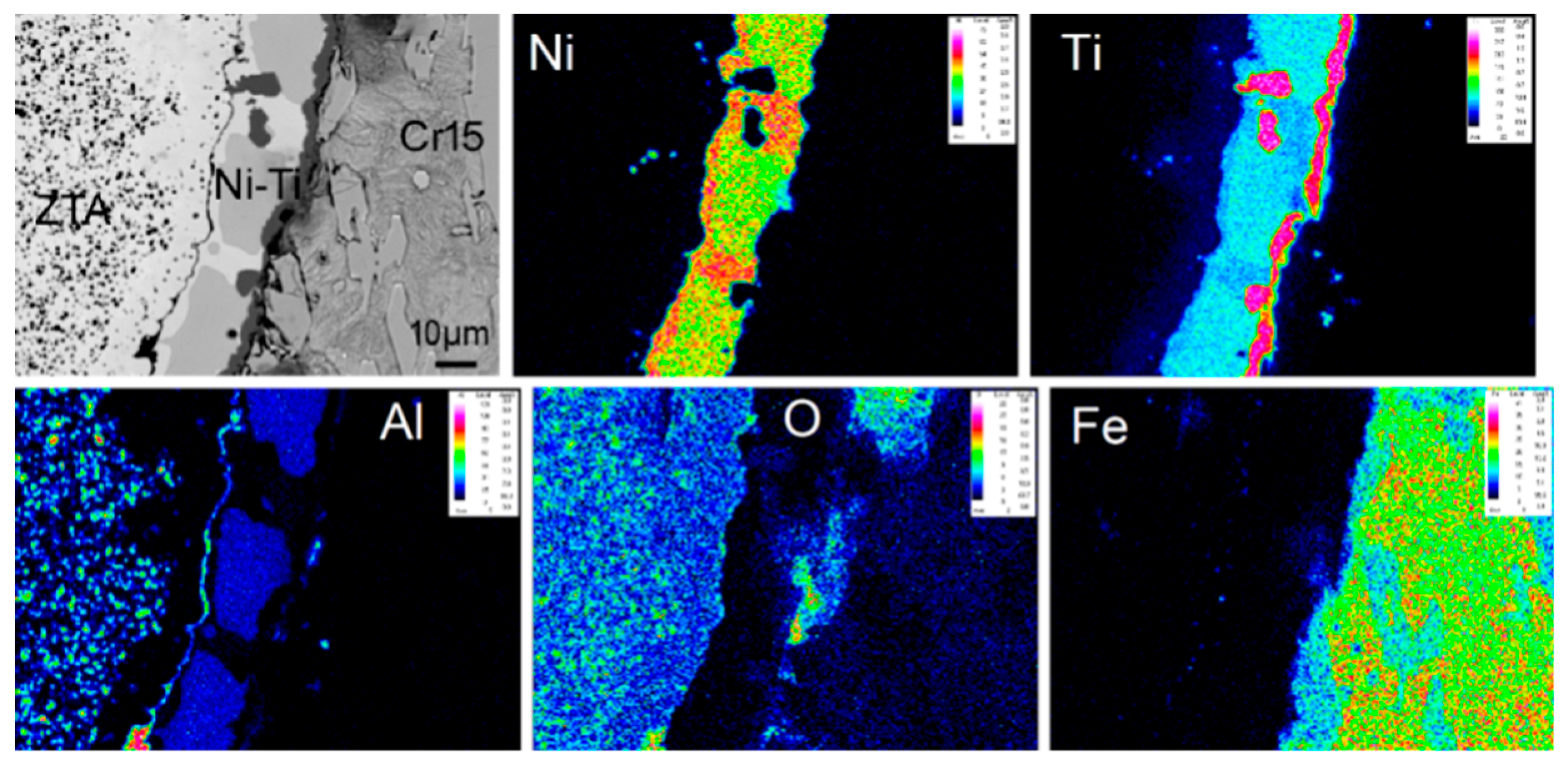
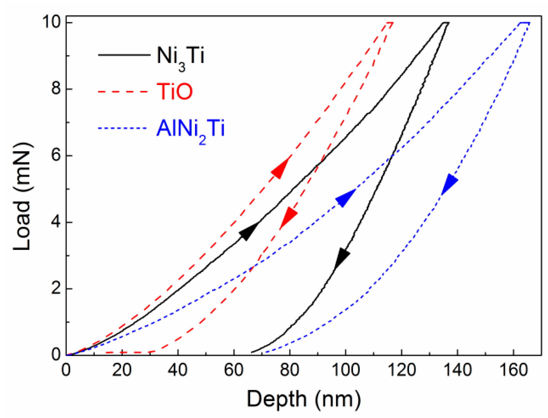
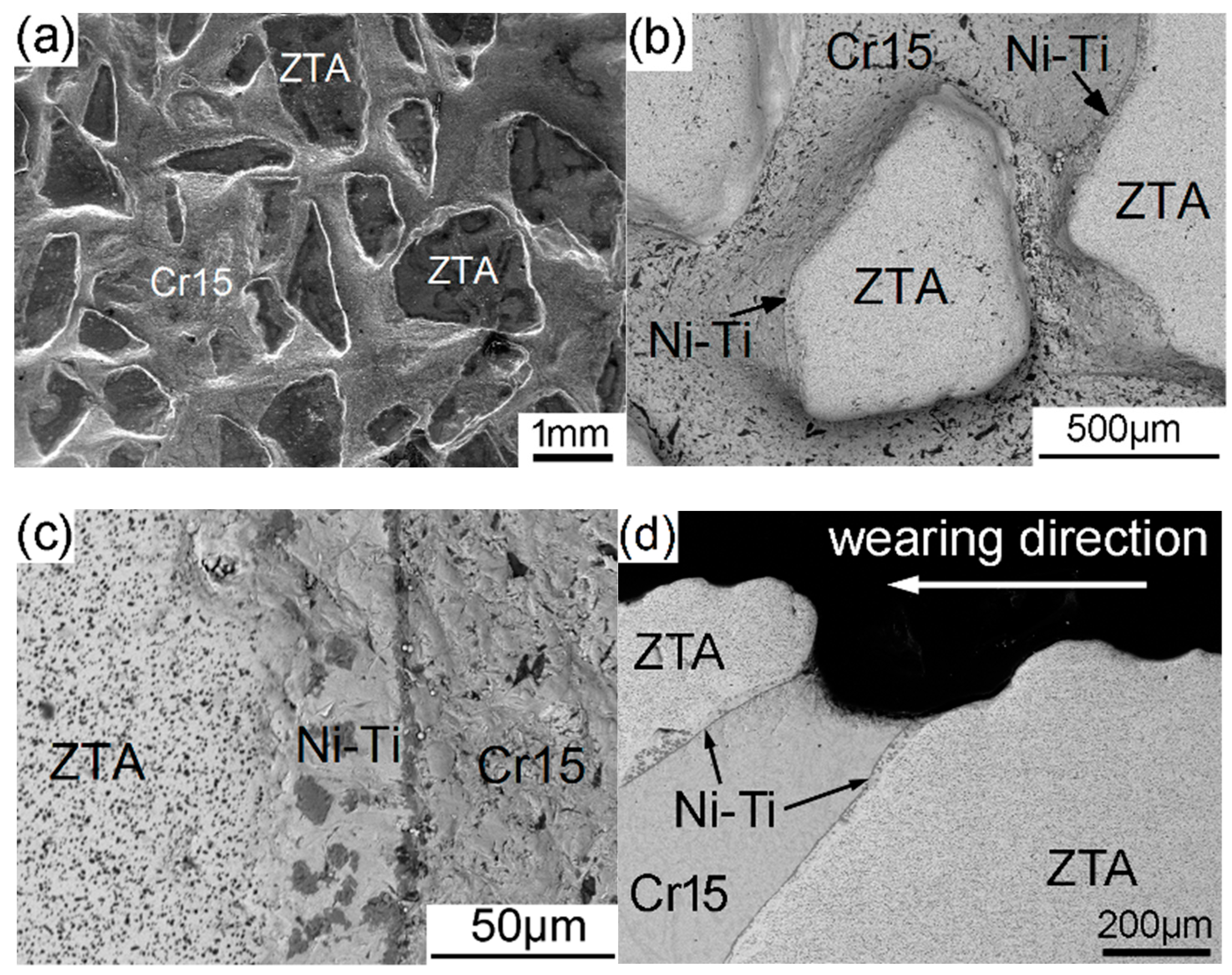
3.2. Analysis of Composite Interface

Figure 5a,b show the segment of the ZTAP/Fe composite. It can be seen that the preform kept the original rectangular shape (with a circular hole) without destruction (Figure 5a) and the thickness of the composite layer reached 15 mm (Figure 5b). The circular hole in the previous preform will benefit the infiltration casting of liquid iron. This indicates that the strength of the preforms in the cavity is high enough to stand against the impact of molten iron during the mold filling processes of castings.
The interfacial microstructure of the composite is shown in Figure 5c,d. A continuous transition layer can be observed between the ZTA particles and the Cr15 matrix. Under high magnification (Figure 5d), it can be seen that around ZTA particles, four different zones existed, which ensure strong metallurgical bonding in the interface. Starting from the ZTA particle and moving outwards, the first zone was the original ZTA particle, while the second zone was an Al-depleted ceramic zone with much lower content of the Al2O3 phase than the first zone. In the third zone, the EDS analysis results, shown in Table 1, together with the EPMA results (Figure 6), illustrate that the main metallurgical phases were Ni3Ti, TiO and AlNi2Ti (point 1, 2, and 3 in Figure 5d, respectively). This indicates that the phases in the Ni–Ti layer did not change after the infiltration casting process compared with the sinter ZTA particle preform.
The elemental mapping results of EPMA at the interfacial area are shown in Figure 6. Based on the elemental diffusion results in Figure 6, we proposed a formation mechanism model at the interface of ZTAP/Fe composites, as shown in Figure 7. It can be seen clearly that Al2O3 on the surface of the ZTA particle decomposed, and thereby the Al and O atoms diffused into the Ni–Ti layer. As a result, the Al element reacted with the Ni–Ti layer and formed a Ni–Ti–Al ternary compound. Furthermore, Ti atoms concentrated on the Ni–Ti layer/Cr15 interface and some O atoms existed at the Ti-rich zone, which formed TiO. Therefore, the transition layer consisted of continuous Ni3Ti, block-shape AlNi2Ti and a TiO zone just next to the Cr15 matrix. In addition, a small amount of Fe was also observed in the Ni–Ti layer due to elemental diffusion as illustrated by Figure 6.
Moreover, the mechanical property of interfacial phases has a significant effect on the interface property and thereby the wear behavior of the composite. In this work, the microhardness of Ni3Ti, TiO and AlNi2Ti in the interface was measured by the nano-indentation method. Figure 8 shows the typical load-depth curves of interfacial phases measured by the nano-indentation method, based on which we obtained the Young’s modulus and Vicker’s hardness, as listed in Table 2. The Vicker’s hardness of Ni3Ti, TiO and AlNi2Ti was 12.5 GPa, 16.1 GPa and 9.2 GPa, respectively. These testing values are very close to the theoretical hardness reported in [30,31,32,33,34,35]. The hardness of these interfacial phases are much higher than common white cast iron (~5.5 GPa), but lower than the ZTA ceramic (12–20 GPa [19,20]). Therefore, we suppose that the mechanical properties of the ZTAP/Fe composite would be improved by the interfacial transition phases (Ni3Ti, TiO, and AlNi2Ti).

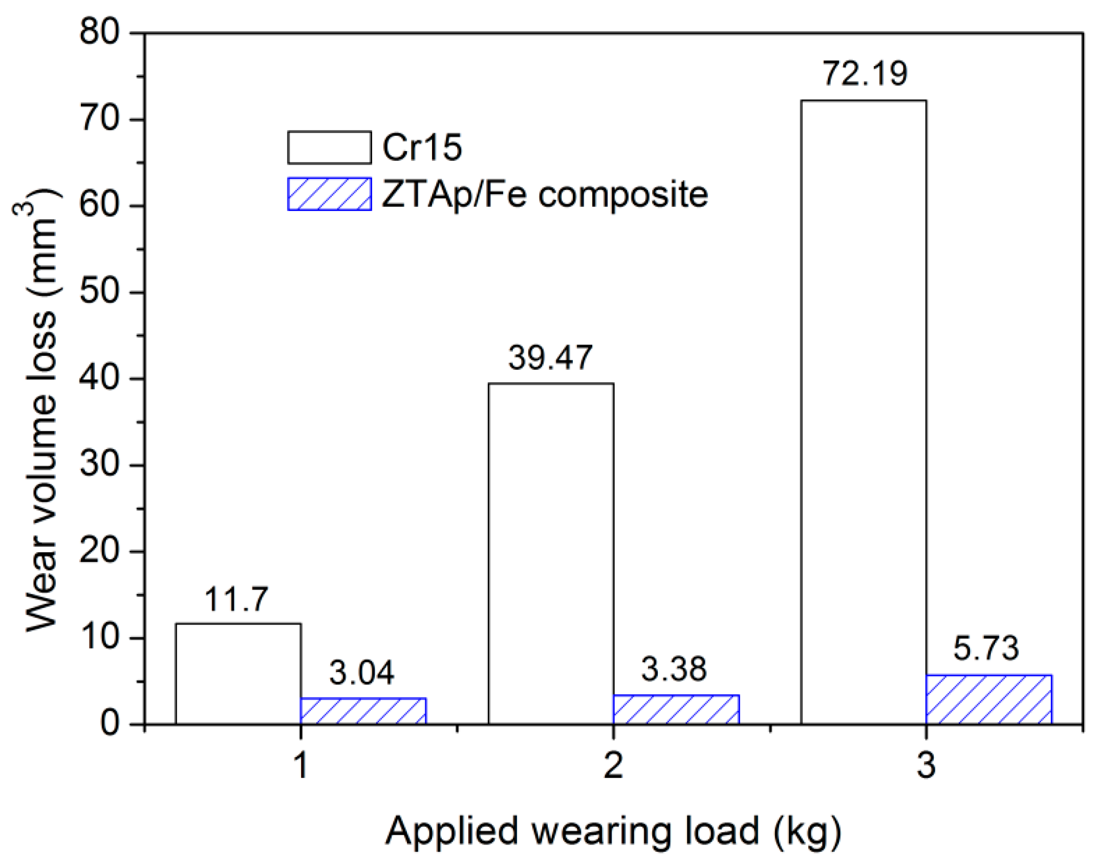
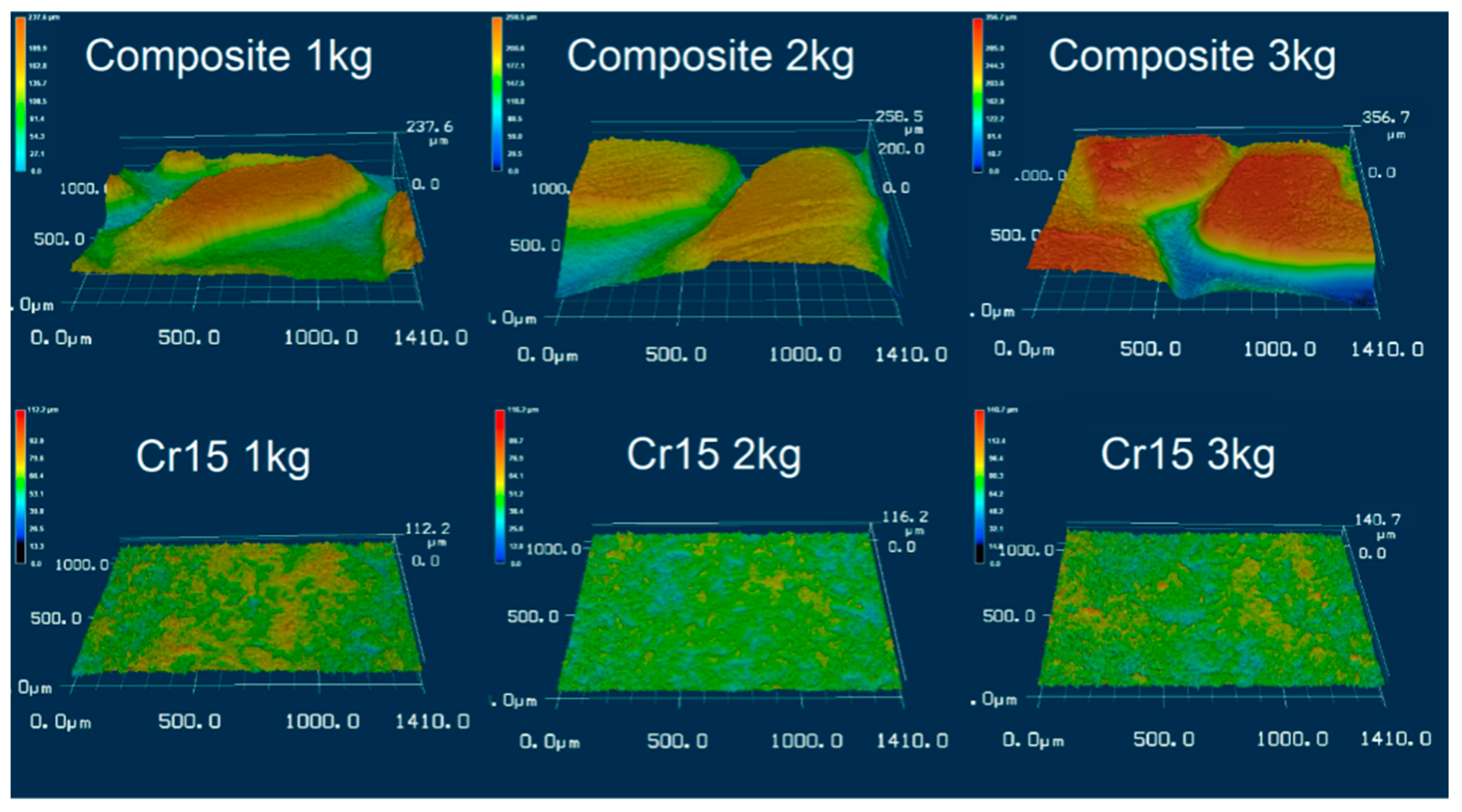
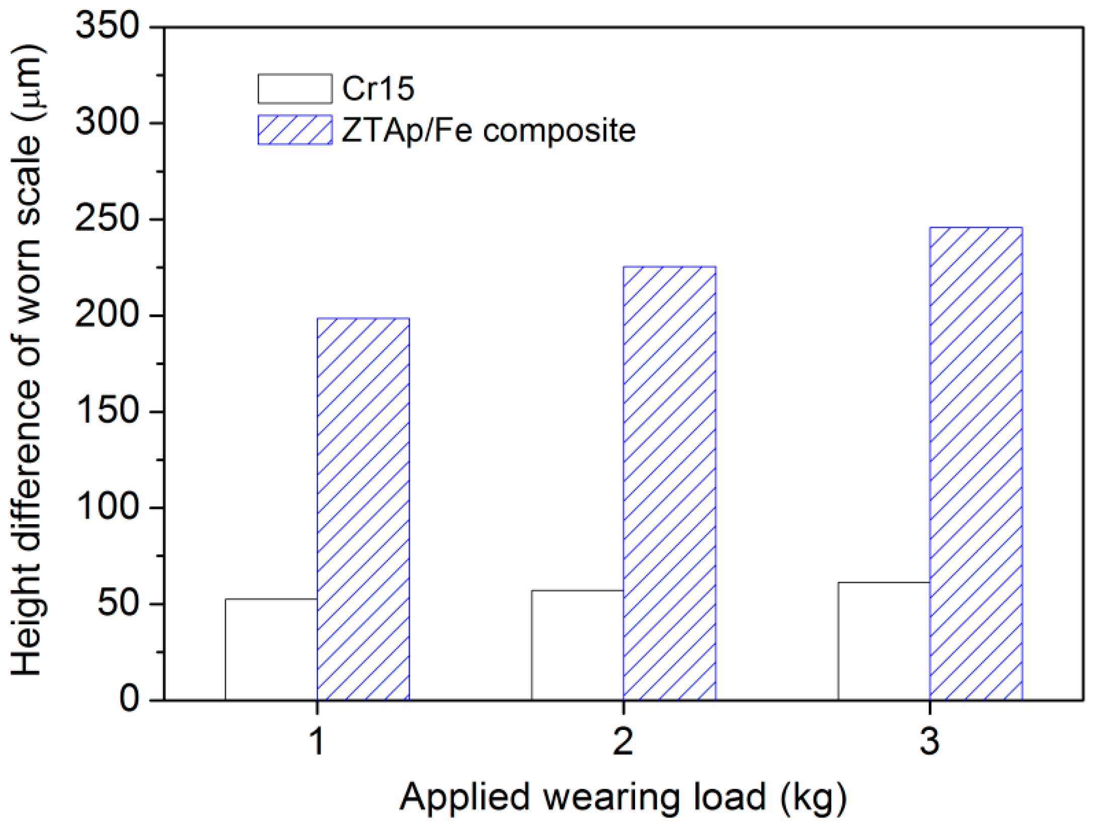
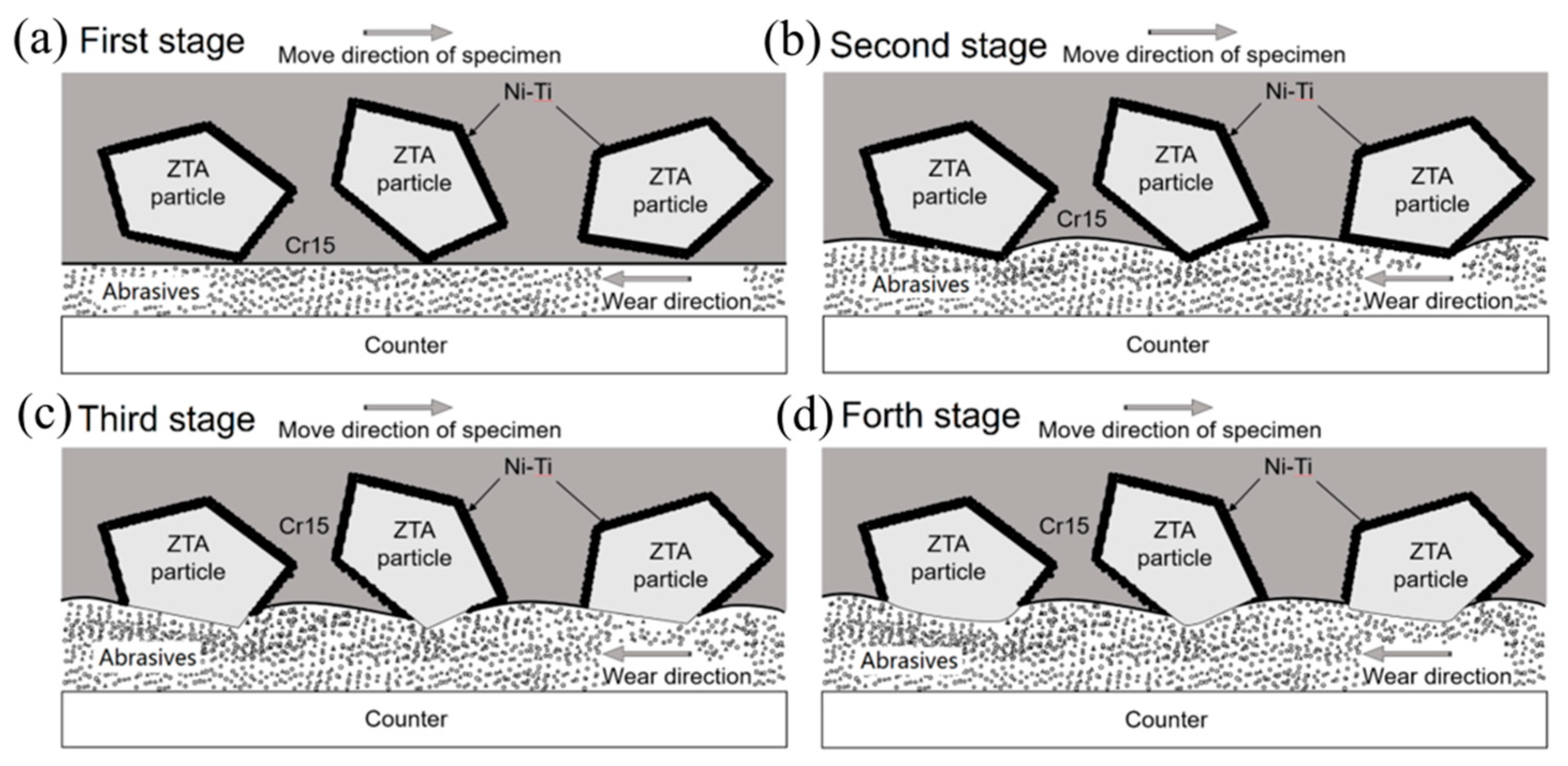
3.3. Wear Resistance of the Composite

The results of the three-body abrasive wear tests are shown in Figure 9. It is apparent that the wear volume loss of the ZTAP/Fe composite was much lower than Cr15 high Cr cast iron after a 2.5 h test. With increasing load from 1 kg to 3 kg (26.1 kPa to 78.4 kPa), the wear volume losses of the Cr15 matrix increased dramatically, while for the ZTAP/Fe composite, the increase rate of wear volume losses was much lower. Under 3 kg wear load, the wear resistance of the composite reached 12.6 times that of the Cr15 matrix, which indicates that the ZTAP/Fe composite showed excellent wear resistance, especially under severe wear conditions.
As illustrated in Figure 10, the worn surface morphology can be observed by the laser scanning confocal topography technique, the corresponding height difference of the worn scale for each tested specimen under different loads is shown in Figure 11. For composites at different wearing loads, the height of the iron matrix was low, which contributed to its deficient wear resistance, while the height of ZTA particles was high owing to its outstanding wear resistance. From Figure 11, at 1 kg wearing load, the ZTA particles protruded above the surrounding iron matrix in composites, with an average height of ~200 μm, compared with the height difference of ~50 μm for the Cr15 specimen. With increasing wearing load, the average height between ZTA particles and the surrounding matrix increased. The thickness reached ~250 μm at 3 kg wearing load. While for the Cr15 specimen, the height difference seemed more or less similar under each wearing load.
Figure 12a,c show the worn surfaces of composite specimens after three-body abrasive wear tests under a 3 kg load. ZTA particles extruded gradually from the worn matrix owing to its higher hardness than the Cr15 matrix. The wear resistance of the composite improved significantly, because the protruded ZTA particles can bear the main wear force by abrasives and protect the surrounding iron matrix from abrasive wear. At the same time, ZTA particles did not peel off from the matrix, which indicates that the ZTA particles were tightly bonded by the transition Ni–Ti metallic layer and surrounding iron matrix. Meanwhile, ZTA particles in the composite were hardly broken or fractured even under a 3 kg load owing to the excellent toughness of the ZTA ceramic with high content of ZrO2 as shown in Figure 12c.
In order to clarify the wearing behavior of the composite more clearly, the sub-surface microstructure was observed on the cross sections of the composite after three-body abrasive wear tests under a 3 kg load. As observed in Figure 12, the typical hard carbides Cr7C3 inside the Cr15 matrix could hardly resist the abrasive wear of SiO2 due to their small size and high brittleness, so the Cr15 matrix part was severely worn. Cracks formed easily when the chromic carbides were crushed and fractured as shown in Figure 12b,c.
The three-body abrasive wear mechanism of ZTAP/Fe composites is shown in Figure 13. At the beginning of the wear test, ZTA particles and matrix were worn simultaneously. Considering that the hardness of ZTA ceramic is higher than iron, the ductile Cr15 matrix was severely worn and concaved gradually, and therefore, the height difference between ZTA and iron became larger and larger; and finally, while keeping an almost constant value, at this condition the ZTA particles bore the main stress and protected iron from further wearing. Meanwhile, the iron matrix bonded ZTA ceramic tightly with the help of the Ni–Ti intermetallic layer, which prevented the ZTA particle from peeling off. Actually, the combination of the strong bonding property between ZTA ceramic and iron, and the protecting effect of ZTA ceramic on iron matrix, gave the composites an advanced wear resistance [36]. The ZTAP/Fe composites show great potential to substitute for traditional wear resistant material and be widely used in industrial applications.

4. Conclusions

The porous ZTA particles preform was prepared by sintering in a vacuum under 1500 °C. The strength of the preform reached 4.1 MPa because of the metallic sintered shell and necks connecting the ZTA particles. The ZTAP/Fe composites were fabricated by an infiltration casting process and the thickness of the composite layer reached 15 mm. The interface of the ZTAP/Fe composites showed metallurgical bonding. A Ni–Ti transition layer consisting of Ni3Ti, TiO and AlNi2Ti existed between the ZTA particles and the iron matrix. The measured hardness was 12.5, 16.1 and 9.2 GPa for Ni3Ti, TiO and AlNi2Ti, respectively. The wear resistance of ZTAP/Fe composites remarkably improved with increasing load and reached 12.6 times the reference Cr15 specimen. This is mainly because the interface was tightly bonded by a transition Ni–Ti layer; and the protruded ZTA particles can bear the main wear force by abrasives and protect the surrounding iron matrix from further failure.

Author Contributions

Y.L. conceived the total investigation, analyzed the data and wrote the manuscript; C.L. and S.T. performed the experiments and analyzed the data; Q.Z. contributed the device; J.W. supervised the experimental part; Z.Z. designed and supervised the whole work; Z.W. revised the paper.

Funding

This work was supported by Guangdong Province Key Area R&D Program (2019B010940001), the Natural Science Foundation of Shaanxi Province of China (2018JM5002), the Key Research and Development Program of Shaanxi Province of China (2019GY-182), the Postdoctoral Science Foundation funded Project of China (No. 2018M631152, 2018T111051), the Postdoctoral Science Foundation funded Project of Shaanxi Province of China, the Fundamental Research Funds for the Central Universities of China (xtr0118008, xzy012019001).

Conflicts of Interest

The authors declare no conflict of interest. The founding sponsors had no role in the design of the study; in the collection, analyses, or interpretation of data; in the writing of the manuscript, and in the decision to publish the results.

References

  1. Rosso, M. Ceramic and metal matrix composites: Routes and properties. J. Mater. Process Technol. 2006, 175, 364–375. [Google Scholar] [CrossRef]
  2. Cardarelli, F. Materials Handbook, 2nd ed.; Springer: London, UK, 2008. [Google Scholar]
  3. Schaffer, J.; Saxena, A.; Antolovich, S.D.; Sanders, T.H., Jr.; Warner, S.B. The Science and Design of Engineering Materials, 2nd ed.; McGraw-Hill Companies Inc.: New York, NY, USA, 1999. [Google Scholar]
  4. Czuprynski, A. Properties of Al2O3/TiO2 and ZrO2 and ZrO2/CaO flame sprayed coatings. Mater. Technol. 2017, 51, 205–212. [Google Scholar]
  5. Tang, S.L.; Gao, Y.M.; Li, Y.F. Recent developments in fabrication of ceramic particle reinforced iron matrix wear resistant surface composite using infiltration casting technology. Ironmak. Steelmak. 2014, 41, 633–640. [Google Scholar] [CrossRef]
  6. Czuprynski, A. Flame spraying of aluminum coatings reinforced with particles of carbonaceous materials as an alternative for laser cladding technologies. Materials 2019, 12, 3467. [Google Scholar] [CrossRef] [PubMed]
  7. Chen, W.; Shi, H.; Xin, H.; He, N.; Yang, W.; Gao, H. Friction and wear properties of Si3N4-hBN ceramic composites using different synthetic lubricants. Ceram. Int. 2018, 44, 16799–16808. [Google Scholar] [CrossRef]
  8. Gorka, J.; Czuprynski, A.; Zuk, M.; Adamiak, M.; Kopysc, A. Properties and structure of deposited nanocrystalline coatings in relation to selected construction materials resistant to abrasive wear. Materials 2018, 11, 1184. [Google Scholar] [CrossRef] [PubMed]
  9. Sequeira, S.; Fernandes, M.H.; Neves, N.; Almeida, M.M. Development and characterization of zirconia-alumina composites for orthopedic implants. Ceram. Int. 2016, 43, 693–703. [Google Scholar] [CrossRef]
  10. Wen, R.L.; Fang, M.H.; Min, X.; Tang, H.; Tang, C.; Wei, Y.Z.; Huang, Z.H.; Liu, Y.H.; Wu, X.W. Effect of ZrO2 addition on mechanical and erosive wear properties of ZTA ceramic. J. Synth. Cryst. 2013, 42, 257–261. [Google Scholar]
  11. Ganesh, I.; Sundararajan, G.; Olhero, S.M.; Ferreira, J.M.F. Influence of chemical composition on sintering ability of ZTA ceramics consolidated from freeze dried franules. Ceram. Int. 2011, 37, 835–841. [Google Scholar] [CrossRef]
  12. Esfahani, H.; Nemati, A.; Salahi, E. The effect of composition and sintering conditions on zircoia toughened alumian (ZTA) nanocomposites. Adv. Mater. Res. 2010, 93, 695–698. [Google Scholar] [CrossRef]
  13. Casellas, D.; Nagl, M.M.; Llanes, L.; Anglada, M. Fracture toughness of alumina and ZTA ceramics: Microstructural coasening effects. J. Mater. Process Technol. 2003, 143, 148–152. [Google Scholar] [CrossRef]
  14. Kern, F.; Palmero, P. Microstructure and mechanical properties of alumina 5 vol.% zirconia nanocomposites prepared by powder coating and powder mixing routes. Ceram. Int. 2013, 39, 673–682. [Google Scholar] [CrossRef]
  15. ASM International Handbook Committee. Properties and selection: Irons, steels, and high-performance alloys. In ASM Handbook; ASM International: Geauga, OH, USA, 1993. [Google Scholar]
  16. Elomari, S.; Boukhili, R.; Lloyd, D.J. Thermal expansion studies of prestrained Al2O3/Al metal matrix composite. Acta Mater. 1996, 44, 1873–1882. [Google Scholar] [CrossRef]
  17. Tada, H.; Kumpel, A.E.; Lathrop, R.E.; Slanina, J.B.; Niewa, P.; Zavracky, P.; Miaoulis, L.N.; Wong, P.Y. Thermal expansion coefficient of polycrystalline silicon and silicon dioxide thin films at high temperatures. J. Appl. Phys. 2000, 87, 4189. [Google Scholar] [CrossRef]
  18. Li, Z.; Bradt, R.C. Thermal expansion and thermal expansion anisotropy of SiC polytypes. J. Am. Ceram. Soc. 1987, 70, 445–448. [Google Scholar] [CrossRef]
  19. Hossen, M.M.; Chowdhury, F.U.Z.; Gafur, M.A.; Abdul Hakim, A.K.M. Structure and mechanical properties of zirconia toughened alumina composites. Int. J. Eng. Res. Tech. 2014, 3, 2128–2134. [Google Scholar]
  20. Li, J.; Zhang, X.S.; Song, P. Toughening mechanism and thermal shock resistance of ZrO2(3Y)/Fe28at-%Al composites evaluated by indentation techniques. Adv. Appl. Ceram. 2014, 113, 404–410. [Google Scholar] [CrossRef]
  21. Sui, Y.D.; Zhou, M.J.; Jiang, Y.H. Characterization of interfacial layer of ZTA ceramic particles reinforced iron matrix composites. J. Alloy. Compd. 2018, 741, 1169–1174. [Google Scholar] [CrossRef]
  22. Zheng, K.H.; Gao, Y.M.; Li, Y.F.; Zhao, S.M.; Wang, J. Three-body abrasive wear resistance of iron matrix composites reinforced with ceramic particles. Proc. Inst. Mech. Eng. Part J 2014, 228, 3–10. [Google Scholar] [CrossRef]
  23. Bahraini, M.; Minghetti, T.; Zoellig, M.; Schubert, J.; Berroth, K.; Schelle, C.; Graule, T.; Kuebler, J. Activated pressureless infiltration of metal-matrix composites with graded activator content. Comp. Part A 2009, 40, 1566–1572. [Google Scholar] [CrossRef]
  24. Vasic, S.; Grobety, B.; Kuebler, J.; Kern, P.; Graule, T. Experimental models for activrationmechanisam of pressureless infiltration in the non-wetting steel-alumina MMC system. Adv. Eng. Mater. 2008, 10, 471–475. [Google Scholar] [CrossRef]
  25. Manonukul, A.; Tange, M.; Srikudvien, P.; Denmud, N.; Wattanapornphan, P. Rheological properties of commercially pure titanium slurry for metallic foam production using replica impregnation method. Powder Technol. 2014, 266, 129–134. [Google Scholar] [CrossRef]
  26. Choi, J.H.; Yang, S.; Kim, Y.D.; Yun, J.Y. The effect of binder content for the pore properties of Fe foam fabricated by slurry coating process. J. Korean Powder Metall. Inst. 2013, 20, 439–444. [Google Scholar] [CrossRef]
  27. Rannou, B.; Velasco, F.; Guzman, S.; Kolarik, V.; Pedraza, F. Aging and thermal behavior of a PVA/Al microspheres slurry for aluminizing purposes. Mater. Chem. Phys. 2012, 134, 360–365. [Google Scholar] [CrossRef]
  28. LeBeau, J.M.; Boonyongmaneerat, Y. Comparison study of aqueous binder systems for slurry-based processing. Mater. Sci. Eng. A 2007, 458, 17–24. [Google Scholar] [CrossRef]
  29. Chen, H.H.; Xing, J.D.; Li, W. Handbook of Wear Resistant Materials, 2nd ed.; Machine Press: Beijing, China, 2012. [Google Scholar]
  30. Li, Y.F.; Tang, S.L.; Gao, Y.M.; Ma, S.Q.; Zheng, Q.L.; Cheng, Y.H. Mechanical and thermodynamic properties of intermetallic compounds in the Ni-Ti system. Int. J. Mod. Phys. B 2017, 31, 1750161. [Google Scholar] [CrossRef]
  31. Chen, Q.; Huang, Z.W.; Zhao, Z.D.; Hu, C.K. First-Principles study on the structural, elastic, and thermodynamics properties of Ni3X (X: Al, Mo, Ti, Pt, Si, Nb, V, and Zr) intermetallic compounds. Appl. Phys. A 2014, 116, 1161. [Google Scholar] [CrossRef]
  32. Tang, S.L.; Li, Y.F.; Wang, Y.R.; Gao, Y.M.; Zheng, Q.L.; Yi, D.W. Theoretical study of mechanical and thermodynamic properties of titanium oxides TixOy. Mater. Chem. Phys. 2018, 213, 638–647. [Google Scholar] [CrossRef]
  33. Jiang, B.; Zhou, G.G.; Huang, K.; Hou, J.G.; Jiao, S.Q.; Zhu, H.M. Structural stability of β-TiO with disordered vacancies: A first-principles calculation. Phys. B 2003, 421, 110–116. [Google Scholar] [CrossRef]
  34. Tang, S.L.; Li, Y.F.; Gao, Y.M.; Zheng, Q.L.; Liu, Z.W.; Ren, Q.Y. First-Principles investigations of the structural, anisotropic mechanical, thermodynamic and electronic properties of the AlNi2Ti compound. Crystals 2018, 8, 93. [Google Scholar] [CrossRef]
  35. Wen, Z.Q.; Zhao, Y.H.; Hou, H.; Wang, B.; Han, P.D. The mechanical and thermodynamic properties of Heusler compounds Ni2XAl (X = Sc, Ti, V) under pressure and temperature: A first-principles study. Mater. Des. 2017, 114, 398–403. [Google Scholar] [CrossRef]
  36. Li, Y.F.; Gao, Y.M. Three-Body abrasive wear behavior of CC/high-Cr WCI composite and its interfacial characteristic. Wear 2010, 268, 511–518. [Google Scholar] [CrossRef]
Figure 1. Schematic diagrams for preparation of the composite: (a) slurry coating process of ceramic particles; (b) graphite mold for preparation of preform; (c) infiltration casting process.
Materials 12 03646 g001
Figure 2. Diagrams of the three-body abrasive wear specimen and corresponding wear principle for the tester.
Materials 12 03646 g002
Figure 3. Macrographs of ZTA ceramic particles after different slurry coating times: (a) 5 times; (b) 10 times; (c) 15 times; (d) 20 times.
Materials 12 03646 g003
Figure 4. Surface morphologies of coated ZTA particle preform (a), sintering neck between two ZTA particles (b), local magnified microstructure of sintered coating (c), and XRD analysis results of sintered particles (d).
Materials 12 03646 g004
Figure 5. The microstructure of ZTAP/Fe composites: (a) distribution of ZTA particles, (b) cross section of infiltration layer, (c) the interfacial morphology, and (d) the high resolution interfacial structure.
Materials 12 03646 g005
Figure 6. The elemental mapping results of interfacial phases by EPMA.
Materials 12 03646 g006
Figure 7. The formation mechanism at the interface of ZTAP/Fe composites.
Materials 12 03646 g007
Figure 8. Typical load-depth curves of interfacial phases measured by thenano-indentation method.
Materials 12 03646 g008
Figure 9. The average wear volume loss of each specimen under different applied loads.
Materials 12 03646 g009
Figure 10. The laser scanning confocal topography (LSCT) of the worn surface of each specimen under different applied loads.
Materials 12 03646 g010
Figure 11. The height difference of the worn scale measured by laser scanning confocal topography for each specimen under different applied loads.
Materials 12 03646 g011
Figure 12. The secondary electron images of the composite after the wear test under the 3 kg load: (a) morphology of the worn surface; (b) protrusion of ZTA particles; (c) translation layer of the worn surface; (d) sub-surface microstructure.
Materials 12 03646 g012
Figure 13. The physical mechanism of the three-body abrasive wear mechanism of ZTAP/Fe composites: (a) the first; (b) second; (c) third; and (d) fourth period of the wear test. The arrows represent the direction of the wear test.
Materials 12 03646 g013
Table 1. Energy dispersive spectrometer (EDS) analysis of the points at ceramic preforms and composite interfaces (at.%).
Point to Be AnalyzedElement
NiTiAlOZrCFeMnCr
Figure 4cPoint 1 3.12 53.5443.34
Point 256.5722.6720.76
Point 374.3925.61
Point 40.7586.07 13.18
Figure 5dPoint 171.5613.868.73 0.224.90 0.73
Point 21.4254.83 42.87 0.88
Point 354.2814.5617.22 0.169.411.662.71
Point 4 1.0443.551.8153.60
Point 50.76 0.5185.834.438.47
Table 2. Micro mechanical properties of interfacial phases measured by thenano-indentation method. The values in parenthesis refer to DFT results calculated by this work.
PhasesYoung’s Modulus/GPaMicro-Hardness/GPa
Ni3Ti211 (253a, 260b)12.5 (10.5a)
TiO225 (267c)16.1 (14.3d)
AlNi2Ti165 (178.1e)9.2 (8.1f)
a–f: Theoretical data from [30,31,32,33,34,35].

