Utilization of Calcium Carbide Residue Using Granulated Blast Furnace Slag

 , ,
, ,  ,
,
Abstract
1. Introduction
2. Experimental Program
2.1. Materials and Sample Preparation
2.2. Test Methods
3. Results and Discussion
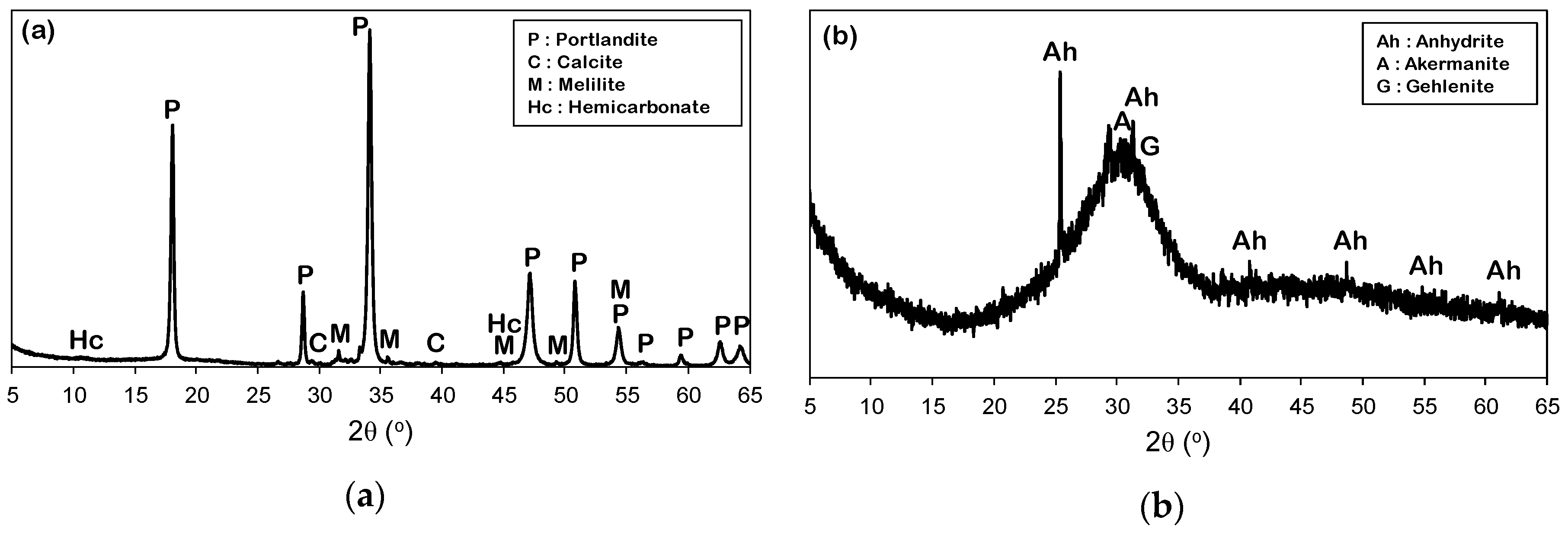
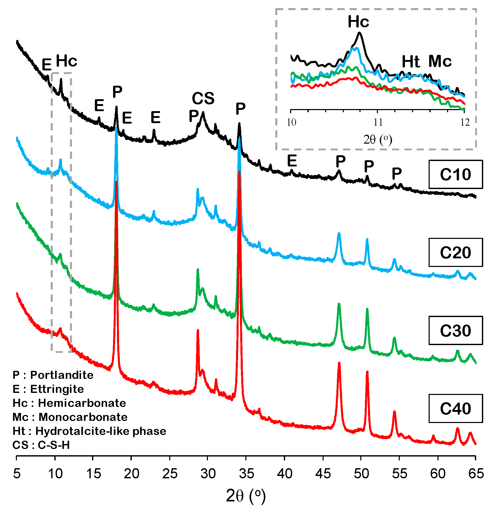
3.1. X-Ray Diffraction
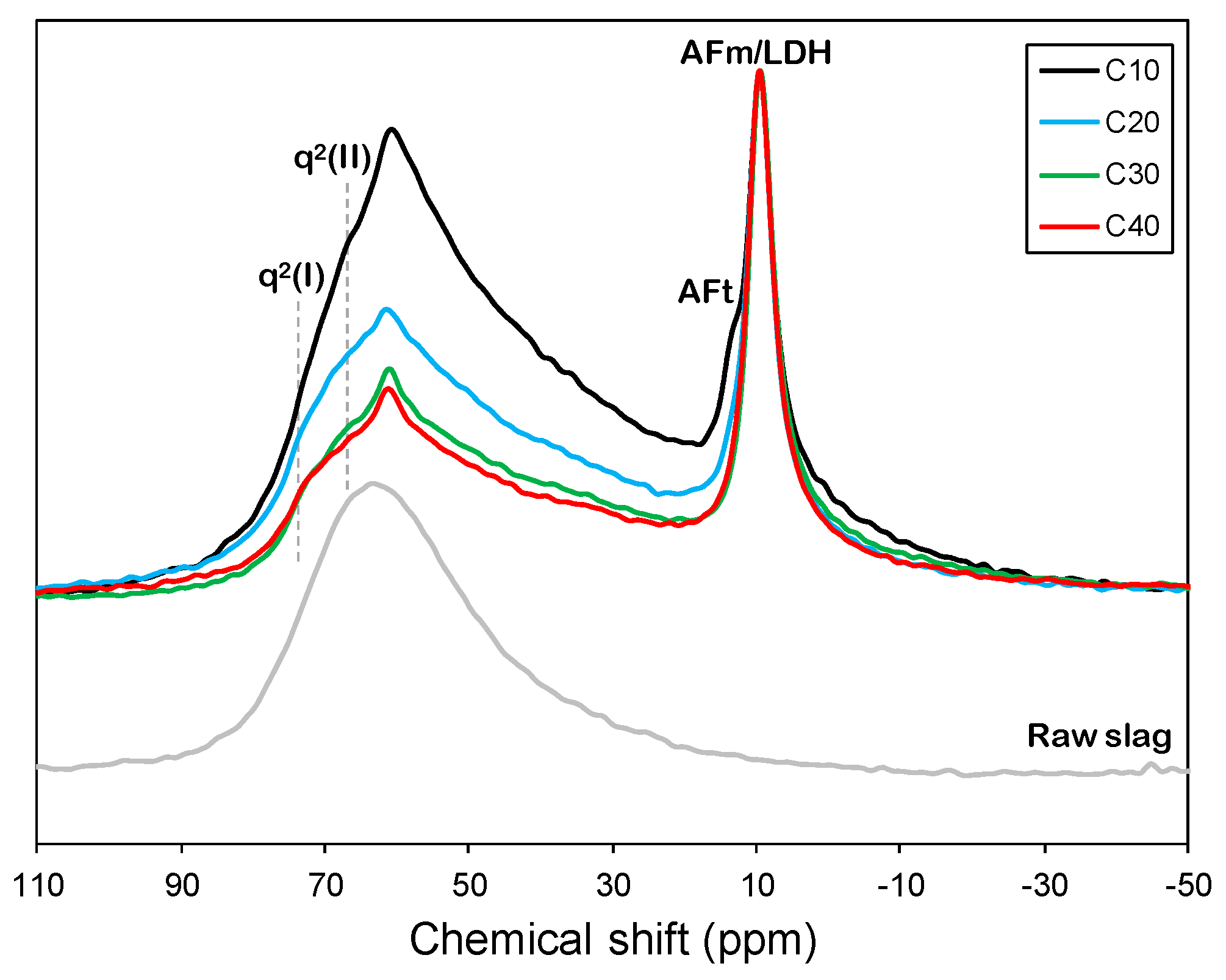
3.2. 27Al MAS NMR
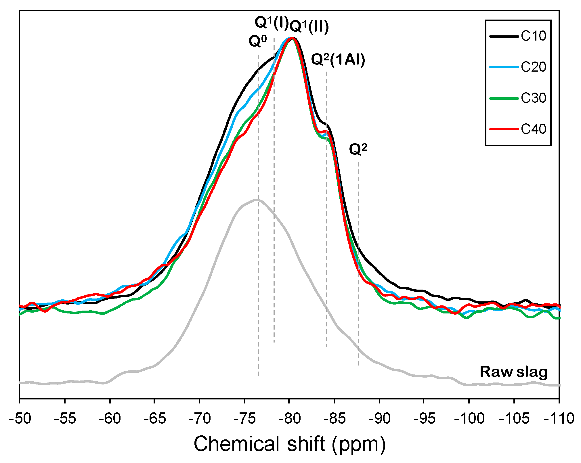
3.3. 29Si MAS NMR
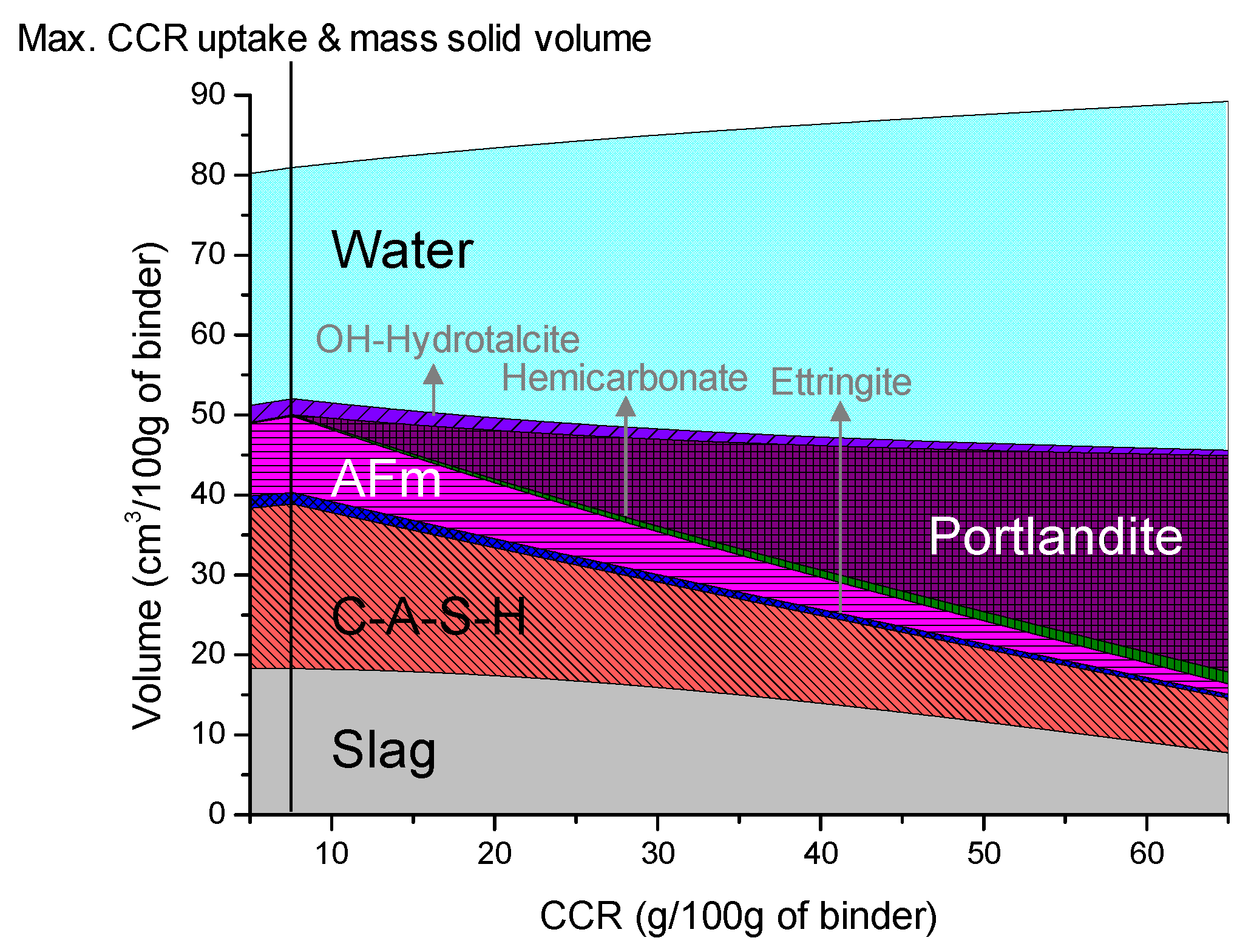
3.4. Thermodynamic Modeling
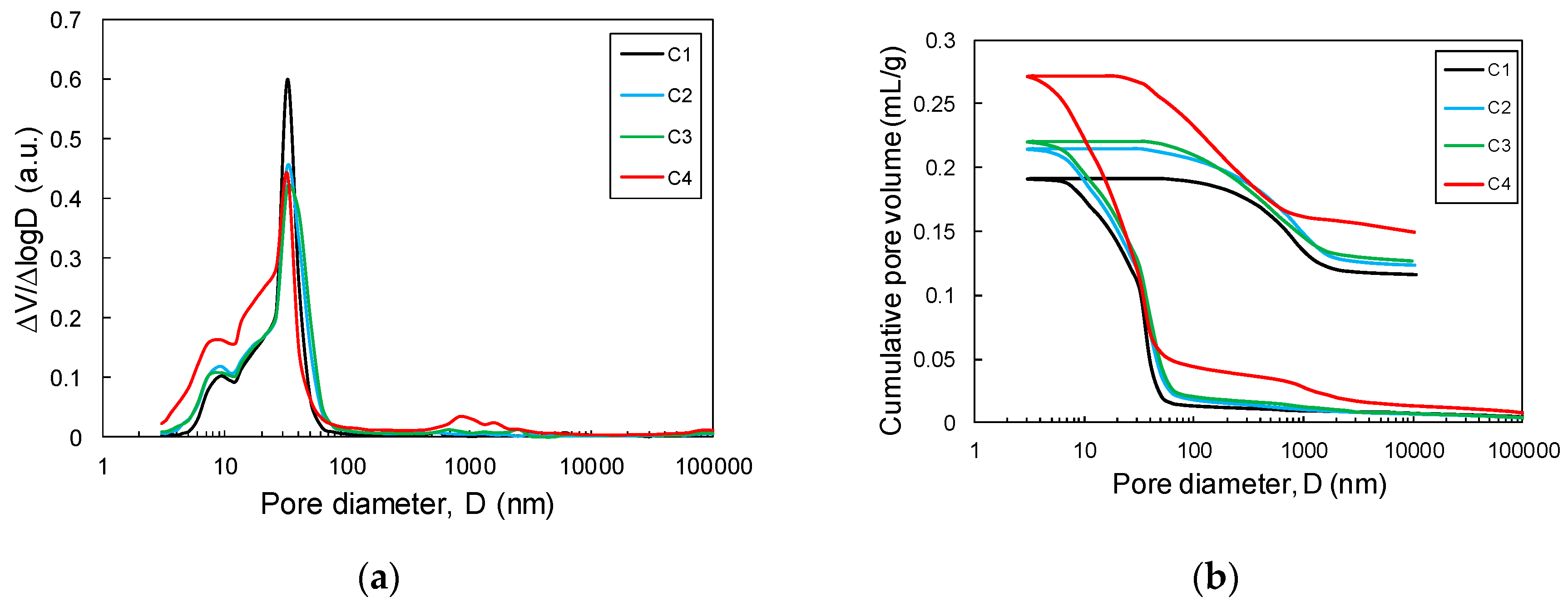
3.5. Pore Characteristics
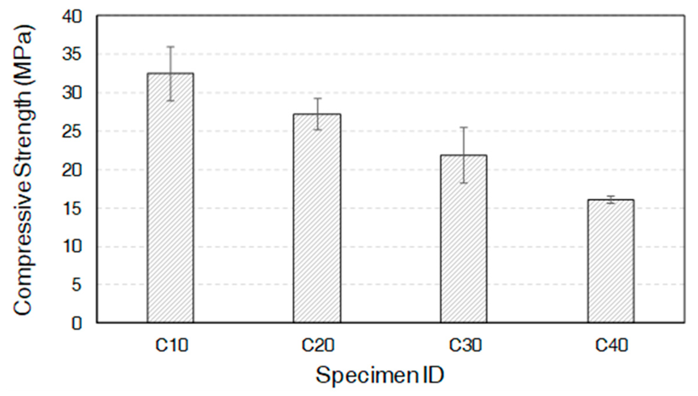
3.6. Unconfined Compressive Strength
4. Conclusions
Author Contributions
Funding
Acknowledgments
Conflicts of Interest
References
- Li, S.; Huang, X.; Muhammad, F.; Yu, L.; Xia, M.; Zhao, J.; Jiao, B.; Shiau, Y.; Li, D. Waste solidification/stabilization of lead–zinc slag by utilizing fly ash based geopolymers. RSC Adv. 2018, 8, 32956–32965. [Google Scholar] [CrossRef]
- Zha, X.; Wang, H.; Xie, P.; Wang, C.; Dangla, P.; Ye, J. Leaching resistance of hazardous waste cement solidification after accelerated carbonation. Cem. Concr. Compos. 2016, 72, 125–132. [Google Scholar] [CrossRef]
- Naroznova, I.; Møller, J.; Scheutz, C. Global warming potential of material fractions occurring in source-separated organic household waste treated by anaerobic digestion or incineration under different framework conditions. Waste Manag. 2016, 58, 397–407. [Google Scholar] [CrossRef] [PubMed]
- Scalia IV, J.; Bohnhoff, G.; Shackelford, C.; Benson, C.; Sample-Lord, K.; Malusis, M.A.; Likos, W. Enhanced bentonites for containment of inorganic waste leachates by GCLs. Geosynth. Int. 2018, 25, 392–411. [Google Scholar] [CrossRef]
- Soares, M.A.; Quina, M.J.; Reis, M.S.; Quinta-Ferreira, R. Assessment of co-composting process with high load of an inorganic industrial waste. Waste Manag. 2017, 59, 80–89. [Google Scholar] [CrossRef]
- Yakubu, Y.; Zhou, J.; Ping, D.; Shu, Z.; Chen, Y. Effects of pH dynamics on solidification/stabilization of municipal solid waste incineration fly ash. J. Environ. Manag. 2018, 207, 243–248. [Google Scholar] [CrossRef]
- Jaturapitakkul, C.; Roongreung, B. Cementing Material from Calcium Carbide Residue-Rice Husk Ash. J. Mater. Civ. Eng. 2003, 15, 470–475. [Google Scholar] [CrossRef]
- Makaratat, N.; Jaturapitakkul, C.; Namarak, C.; Sata, V. Effects of binder and CaCl2 contents on the strength of calcium carbide residue-fly ash concrete. Cem. Concr. Compos. 2011, 33, 436–443. [Google Scholar] [CrossRef]
- Tanalapasakul, A. Document from M. Thai Industrial Company Limited; M Thai Industrial Co., Ltd.: Samutsakorn, Thailand, 1998. [Google Scholar]
- Lavoie, K.H. Toxicity of carbide waste to heterotrophic microorganisms in caves. Microb. Ecol. 1980, 6, 173–179. [Google Scholar] [CrossRef]
- Makaratat, N.; Jaturapitakkul, C.; Laosamathikul, T. Effects of Calcium Carbide Residue–Fly Ash Binder on Mechanical Properties of Concrete. J. Mater. Civ. Eng. 2010, 22, 1164–1170. [Google Scholar] [CrossRef]
- Rattanashotinunt, C.; Thairit, P.; Tangchirapat, W.; Jaturapitakkul, C. Use of calcium carbide residue and bagasse ash mixtures as a new cementitious material in concrete. Mater. Des. 2013, 46, 106–111. [Google Scholar] [CrossRef]
- Horpibulsuk, S.; Munsrakest, V.; Udomchai, A.; Chinkulkijniwat, A.; Arulrajah, A. Strength of sustainable non-bearing masonry units manufactured from calcium carbide residue and fly ash. Constr. Build. Mater. 2014, 71, 210–215. [Google Scholar] [CrossRef]
- Lothenbach, B.; Kulik, D.A.; Matschei, T.; Balonis, M.; Baquerizo, L.; Dilnesa, B.; Miron, G.D.; Myers, R.J. Cemdata18: A chemical thermodynamic database for hydrated Portland cements and alkali-activated materials. Cem. Concr. Res. 2019, 115, 472–506. [Google Scholar] [CrossRef]
- Helgeson, H.C.; Kirkham, D.H.; Flowers, G.C. Theoretical prediction of the thermodynamic behavior of aqueous electrolytes by high pressures and temperatures; IV, Calculation of activity coefficients, osmotic coefficients, and apparent molal and standard and relative partial molal properties to 600 degrees C and 5kb. Am. J. Sci. 1981, 281, 1249–1516. [Google Scholar]
- Kim, M.S.; Jun, Y.; Lee, C.; Oh, J.E. Use of CaO as an activator for producing a price-competitive non-cement structural binder using ground granulated blast furnace slag. Cem. Concr. Res. 2013, 54, 208–214. [Google Scholar] [CrossRef]
- Myers, R.J.; Bernal, S.A.; Gehman, J.D.; van Deventer, J.S.; Provis, J.L. The role of Al in cross-linking of alkali-activated slag cements. J. Am. Ceram. Soc. 2015, 98, 996–1004. [Google Scholar] [CrossRef]
- Mobasher, N.; Bernal, S.A.; Provis, J.L. Structural evolution of an alkali sulfate activated slag cement. J. Nucl. Mater. 2016, 468, 97–104. [Google Scholar] [CrossRef]
- Richardson, I.G.; Groves, G.W. Microstructure and microanalysis of hardened cement pastes involving ground granulated blast-furnace slag. J. Mater. Sci. 1992, 27, 6204–6212. [Google Scholar] [CrossRef]
- Skibsted, J.; Jakobsen, H.J. Characterization of the Calcium Silicate and Aluminate Phases in Anhydrous and Hydrated Portland Cements by 27Al and 29Si MAS NMR Spectroscopy. In Nuclear Magnetic Resonance Spectroscopy of Cement-Based Materials; Springer: Berlin/Heidelberg, Germany, 1998; pp. 3–45. [Google Scholar]
- Andersen, M.D.; Jakobsen, H.J.; Skibsted, J. Characterization of white Portland cement hydration and the CSH structure in the presence of sodium aluminate by 27Al and 29Si MAS NMR spectroscopy. Cem. Concr. Res. 2004, 34, 857–868. [Google Scholar] [CrossRef]
- Seo, J.H.; Park, S.M.; Lee, H.K. Evolution of the binder gel in carbonation-cured Portland cement in an acidic medum. Cem. Concr. Res. 2018, 109, 81–89. [Google Scholar] [CrossRef]
- Bernal, S.A.; San Nicolas, R.; Myers, R.J.; de Gutiérrez, R.M.; Puertas, F.; van Deventer, J.S.; Provis, J.L. MgO content of slag controls phase evolution and structural changes induced by accelerated carbonation in alkali-activated binders. Cem. Concr. Res. 2014, 57, 33–43. [Google Scholar] [CrossRef]
- Park, S.M.; Jang, J.; Lee, N.; Lee, H. Physicochemical properties of binder gel in alkali-activated fly ash/slag exposed to high temperatures. Cem. Concr. Res. 2016, 89, 72–79. [Google Scholar] [CrossRef]
- Bernal, S.A.; Provis, J.L.; Walkley, B.; Nicolas, R.S.; Gehman, J.D.; Brice, D.G.; Kilcullen, A.R.; Duxson, P.; Van Deventer, J.S. Gel nanostructure in alkali-activated binders based on slag and fly ash, and effects of accelerated carbonation. Cem. Concr. Res. 2013, 53, 127–144. [Google Scholar] [CrossRef]
- Wang, S.-D.; Scrivener, K.L. 29Si and 27Al NMR study of alkali-activated slag. Cem. Concr. Res. 2003, 33, 769–774. [Google Scholar] [CrossRef]
- Collepardi, M. A state-of-the-art review on delayed ettringite attack on concrete. Cem. Concr. Compos. 2003, 25, 401–407. [Google Scholar] [CrossRef]
- Park, S.; Jang, J.; Lee, H. Unlocking the role of MgO in the carbonation of alkali-activated slag cement. Inorg. Chem. Front. 2018, 5, 1661–1670. [Google Scholar] [CrossRef]
- Richardson, I.G.; Groves, G.W. The structure of the calcium silicate hydrate phases present in hardened pastes of white Portland cement/blast-furnace slag blends. J. Mater. Sci. 1997, 32, 4793–4802. [Google Scholar] [CrossRef]
- Kunther, W.; Dai, Z.; Skibsted, J. Thermodynamic modeling of hydrated white Portland cement–metakaolin–limestone blends utilizing hydration kinetics from 29Si MAS NMR spectroscopy. Cem. Concr. Res. 2016, 86, 29–41. [Google Scholar] [CrossRef]
- Shi, Z.; Lothenbach, B.; Geiker, M.R.; Kaufmann, J.; Leemann, A.; Ferreiro, S.; Skibsted, J. Experimental studies and thermodynamic modeling of the carbonation of Portland cement, metakaolin and limestone mortars. Cem. Concr. Res. 2016, 88, 60–72. [Google Scholar] [CrossRef]
- Song, F.; Yu, Z.; Yang, F.; Lu, Y.; Liu, Y. Microstructure of amorphous aluminum hydroxide in belite-calcium sulfoaluminate cement. Cem. Concr. Res. 2015, 71, 1–6. [Google Scholar] [CrossRef]
- Kim, G.M.; Jang, J.G.; Naeem, F.; Lee, H.K. Heavy Metal Leaching, CO2 Uptake and Mechanical Characteristics of Carbonated Porous Concrete with Alkali-Activated Slag and Bottom Ash. Int. J. Concr. Struct. Mater. 2015, 9, 283–294. [Google Scholar] [CrossRef]
- Silva, D.; John, V.M.; Ribeiro, J.; Roman, H.; Ribeiro, J.L. Pore size distribution of hydrated cement pastes modified with polymers. Cem. Concr. Res. 2001, 31, 1177–1184. [Google Scholar] [CrossRef]
- Wee, T.H.; Matsunaga, Y.; Watanabe, Y.; Sakai, E. Microstructure and strength properties of high strength concretes containing various mineral admixtures. Cem. Concr. Res. 1995, 25, 715–720. [Google Scholar] [CrossRef]


| (wt.%) | Al2O3 | CaO | Fe2O3 | MgO | Na2O | P2O5 | SiO2 | TiO2 | LOI 1 |
|---|---|---|---|---|---|---|---|---|---|
| CCR | 1.83 | 70.10 | 0.14 | 0.50 | 0.05 | 0.01 | 4.70 | 0.02 | 21.60 |
| Slag | 11.50 | 47.70 | 0.60 | 3.00 | - | 0.60 | 32.40 | 0.50 | 0.29 |
| Specimen ID | Anhydrous Slag | Q1 | Q2(1Al) | Q2 | Q3(1Al) | MCL | |||||||
|---|---|---|---|---|---|---|---|---|---|---|---|---|---|
| ppm | % | ppm | % | ppm | % | ppm | % | ppm | % | ppm | % | ||
| C10 | −74.0 | 50.8 | −78.5 | 16.8 | −80.8 | 9.0 | −84.0 | 16.5 | −87.0 | 6.5 | −89.0 | 0.4 | 4.42 |
| C20 | −74.0 | 46.6 | −77.0 | 10.9 | −80.9 | 31.2 | −84.7 | 7.1 | −86.7 | 4.3 | 2.72 | ||
| C30 | −74.0 | 44.0 | −78.5 | 19.5 | −81.0 | 22.3 | −84.5 | 5.1 | −86.0 | 9.1 | 2.80 | ||
| C40 | −74.0 | 42.6 | −78.7 | 22.5 | −80.9 | 21.2 | −84.6 | 10.6 | −86.9 | 3.0 | 2.87 | ||
| Specimen ID | Median Pore Diameter (nm) | Porosity (%) | Total Intrusion Volume (mL/g) |
|---|---|---|---|
| C10 | 17.9 | 35.5 | 0.19 |
| C20 | 14.2 | 38.0 | 0.21 |
| C30 | 14.4 | 38.7 | 0.22 |
| C40 | 10.0 | 42.9 | 0.27 |
© 2019 by the authors. Licensee MDPI, Basel, Switzerland. This article is an open access article distributed under the terms and conditions of the Creative Commons Attribution (CC BY) license (http://creativecommons.org/licenses/by/4.0/).
Share and Cite
Seo, J.; Park, S.; Yoon, H.N.; Jang, J.G.; Kim, S.H.; Lee, H.K. Utilization of Calcium Carbide Residue Using Granulated Blast Furnace Slag. Materials 2019, 12, 3511. https://doi.org/10.3390/ma12213511
Seo J, Park S, Yoon HN, Jang JG, Kim SH, Lee HK. Utilization of Calcium Carbide Residue Using Granulated Blast Furnace Slag. Materials. 2019; 12(21):3511. https://doi.org/10.3390/ma12213511
Chicago/Turabian StyleSeo, Joonho, Solmoi Park, Hyun No Yoon, Jeong Gook Jang, Seon Hyeok Kim, and H. K. Lee. 2019. "Utilization of Calcium Carbide Residue Using Granulated Blast Furnace Slag" Materials 12, no. 21: 3511. https://doi.org/10.3390/ma12213511
APA StyleSeo, J., Park, S., Yoon, H. N., Jang, J. G., Kim, S. H., & Lee, H. K. (2019). Utilization of Calcium Carbide Residue Using Granulated Blast Furnace Slag. Materials, 12(21), 3511. https://doi.org/10.3390/ma12213511