Abstract
The electronic structure, magnetic properties and strain response of N-a-TiS3 nanoribbons are investigated by first-principles calculations. We find that the magnetic ground state is strongly dependent on width of a-TiS3. When N equals an odd number the ground state is a ferromagnetic (FM) metal, meanwhile, when N equals an even number the ground state is an anti-ferromagnetic (AFM) metal. More interestingly, a tensile strain as large as 6% can tune the 9-a-TiS3 nanoribbon from a FM metal to a half metal. A 4% tensile strain also causes a phase transition from AFM to FM ground state for 10-a-TiS3 nanoribbon. Our findings show that N-a-TiS3 is a promising candidate for spintronic and electronic applications.
1. Introduction
The properties of materials are essentially associated with dimensionality. Due to low dimensionality, quantum confinement and their promising applications in spintronics, optronics, thermoelectrics [1,2,3,4], etc., one-dimensional (1D) nanostructures, such as nanotubes, nanowires, nanobelts, and nanoribbons, have drawn a lot of attention during the past two decades [5,6,7]. When graphene is cut into 1D graphene nanoribbons, even more fantastic properties are predicted and some have already been verified experimentally [8,9,10,11]. Especially, the zigzag graphene nanoribbons (ZGNRs) were predicted to be antiferromagnetic semiconductors [12,13]. More interestingly, many theoretical studies have demonstrated that the half-metallicity in ZGNRs can be realized under external transverse electric fields [14,15], or by selective chemical modifications [16,17,18]. Many other methods, like doping [17] or defects [19], were applied to tune or control the magnetism in ZGNRs. Moreover, ZGNRs can carry a spin current response to an external electric field, which opens a new path to the application of spintronics [14]. In addition to ZGNRs, magnetism hasalso been predicted in many other nanoribbons, such as CoTe [1], Fe2GeAl [2], MnSi [3], BN [20], MoS2 [21], black and blue phosphorus [22,23], andZnO [24].
Very recently, a new two-dimensional (2D) material, namely TiS3, has been successfully synthesized [25,26,27,28]. It is reported that monolayer TiS3exhibits a direct band gap of 1.1–1.2 eV [29], making the bandgap of TiS3 comparable to that of silicon (1.1 eV). Also, numerical results show that the bandgap of TiS3 is quite robust, almost independent of layer thickness, vertical strain and stacking order [30]. Moreover, a recent theoretical study proposed that TiS3 is expected to have a higher electron mobility of 10,000 cm2V−1s−1 [29]. Such a robust bandgap and ultrahigh electron mobility make TiS3 a good candidate for nanoelectronics and optoelectronics application. The elastic modulus, carrier mobility and band structure of TiS3 are strongly anisotropic due to its highly anisotropic crystal. Experimentally, nanoribbons of TiS3 were successfully prepared [25,26,27,28]. Although, there are several studies on nanoribbons of TiS3 [25,26,27,28,31,32,33], the magnetism of TiS3 nanoribbon still lacks systematic study.
In this article, using first-principles calculation, we systematically study the magnetic properties of TiS3 nanoribbon. Our results show that a-TiS3 NR is a spin-polarized metal with local magnetic moments at the edge, while b-TiS3 NR is nonmagnetic semiconductor. More interestingly, the magnetic ground state of N-a-TiS3 NRs (N = 7, 8, 9, 10, 11) are width dependent. When N is odd, the ground state is ferromagnetism (FM), meanwhile the ground state is anti-ferromagnetism (AFM)when N is even. This magnetic behavior is very different from other magnetic nanoribbons, such as zigzag black phosphorene nanoribbons [22] and zigzag graphene nanoribbons [12,13], whose magnetic properties are almost independent on the width of nanoribbon. We also find that compressive strain almost does not change the magnetic and electric properties of a-TiS3 NRs. However, according to our calculations in 9-a-TiS3 NR and 10-a-TiS3, tensile strain can change the magnetic and electric properties dramatically. 9-a-TiS3 NR becomes a half metal under a tensile as large as 6%, and the AFM ground state of 10-a-TiS3 is tuned into a FM ground state at about 4% tensile strain. Our findings show that the a-TiS3 NRs are promising candidates for spintronics and electronics application.
2. Methods
All the calculations were carried with Vienna ab initio Simulation Package (VASP, version 5.3.2, University of Vienna, Vienna, Austria) [34,35]. The frozen-core projector augmented wave (PAW) method and the generalized gradient approximation (GGA) of Perdew–Burke–Ernzerhof (PBE) [36] were adopted. Cutoff energy was set as 500 eV for plane-wave expansion of the electronic wave function, and appropriate k-point meshes (9 × 1 × 1) were used for geometric optimization and self-consistent calculation. All structures were relaxed until the force on each atom was less than 0.01 eV/ Å. The energy convergence criteria were set to 1.0 × 10⁻⁶ eV. A vacuum spacing of 15 Å was used so that the interaction in the non-periodic directions can be neglected. Since both Ti and S are not heavy elements, spin-orbit coupling (SOC) is expected to be small, thus the spin-orbit interaction is not included in all calculations.
3. Results and Discussion
The unit cell of monolayer TiS3 is a rectangle. Our optimized lattice constants are a = 5.02 Å, b = 3.40 Å which are in good agreement with previous experimental result (4.96 and 3.40 Å) [37], and theoretical result (5.02 and 3.41 Å) [31]. There are two particular ways to cut monolayer TiS3 into nanoribbons (cutting along the a axis or b axis). Then, two types of nanoribbons are indicated as N-a-TiS3 NR and N-b-TiS3 NR, where N indicates the number of Ti atoms in the unit cell of ribbon and a-TiS3 NR and b-TiS3 NR are along the a and b lattice vectors, respectively. Our calculations show that N-b-TiS3 NRs are semiconductors without any local magnetic moment, which is consistent with previous theoretical results [31]. Thus, in the following discussion we will eliminate the N-b-TiS3 NRs and mainly consider the N-a-TiS3 NRs.
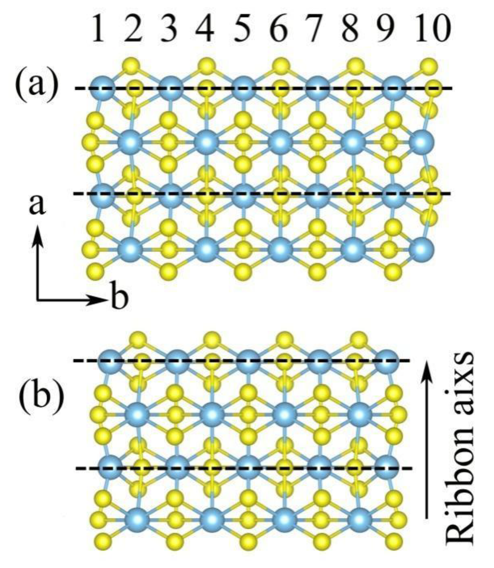
Here, we take N = 7–11 for a-TiS3 NRs. Figure 1 shows the crystal structure of 10-a-TiS3 NR and 9-a-TiS3 NR. In particular, edge atoms may influence the physical properties. For a-TiS3 NR, the edge atoms are S and Ti with dangling bonds which are local states around Fermi level as shown later. However, there are some differences in crystal structure between 9-a-TiS3 NR and 10-a-TiS3 NR. Dashed lines in Figure 1a,b also indicate the TiS3 chain in monolayer TiS3. In 9-a-TiS3 NR, the terminal atoms for every TiS3 chain are the same, namely both of two edge atoms are Ti or S atoms for the same chain as shown in Figure 1b. However, in 10-a-TiS3 NR, the edge atoms for every TiS3 chain are different, i.e., one terminal atom is Ti and the other is an S atom shown in Figure 1a. Moreover, for N equal to all other odd numbers (or even numbers) the edge atom arrangement is the same as the N = 9 (or 10). This different edge atom arrangement will cause a different magnetic ground state of two NRs as discussed below.
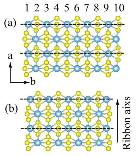
Figure 1.
(a) The crystal structure of 10-a-TiS3nanoribbon (NR), and; (b) the crystal structure of 9-a-TiS3. Two dashed lines indicate the unit cell of nanoribbon along the a lattice vector. The dashed lines indicate the TiS3 chain in monolayer TiS3.
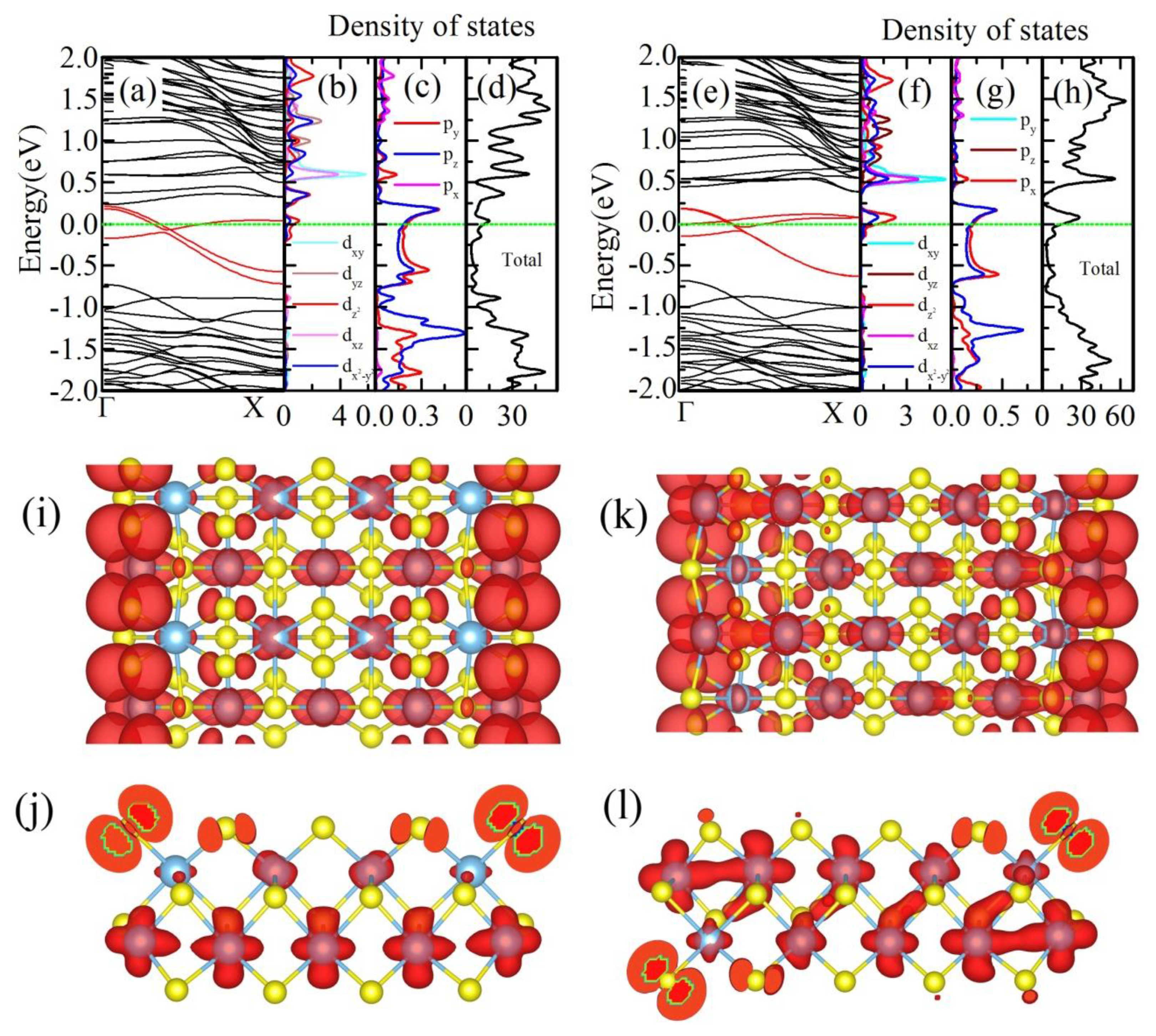
Firstly, we calculate the electronic structure of 9-a-TiS3 NR and 10-a-TiS3 NR under GGA approximation without any spin polarization. The electronic structures of two nanoribbons are shown Figure 2. Three bands, denoted by red color, cross the Fermi energy indicating the metallic behavior of a-TiS3 NR (shown in Figure 2a,e). Further analysis shows that these three bands are the edge states. Density of states (DOS), shown in Figure 2, indicate that three bands crossing the Fermi level are mainly contributed by the unbonding and states of edge S atoms and and of edge Ti atoms. A peak of DOS near the Fermi energy, as shown in total DOS, indicates the possibility of spin polarization driven by Stoner instability [38].
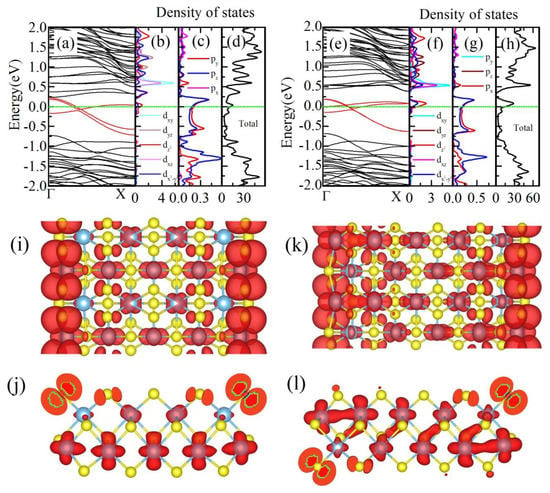
Figure 2.
(a) and (e) are the band structures of 9-a-TiS3 NR and 10-a-TiS3, respectively, within the GGA calculation. Three bands, which cross the Fermi level and are denoted by red color, are the edge states. (b) and (f) are the density of states of d-orbital of edge Ti atoms in 9-a-TiS3 NR and 10-a-TiS3 NR respectively. (c) and (g) are the density of states of p-states of edge S atoms in 9-a-TiS3 and 10-a-TiS3 NRs; (d) and (h) are the total density of states of 9-a-TiS3 and 10-a-TiS3 NRs respectively. (i) and (j) are the charge density of three red bands of 9-a-TiS3 NR. (k) and (l) are the charge density of three red bands of 10-a-TiS3 NR. (i) and (k) are the top view while (j) and (l) are the side view along the period direction.
To clarify the effect of edge atoms, we plot the charge density isosurfaces of these three bands which cross the Fermi energy and the results are shown in Figure 2i–l. These pictures clearly illustrate the charge density is mainly localized at edge S and Ti atoms which again proves that three bands denoted by red lines are indeed the edge states. As we discussed before, the arrangement of edge atoms is different between 9-a-TiS3 NR and 10-a-TiS3 NR. Thus, charge distribution is different for these two a-TiS3 NRs. In 9-a-TiS3 NR, the charges are mainly localized at edge S atoms which are in the TiS3 chain, whose the end atoms are both sulfur atoms, shown in Figure 2i,j. The p orbital shape of charge density on edge S atoms are the hybridization of and unbonding state. However, the contribution of Ti-d state in TiS3 chain with two end Ti atoms is more complicated. The charge distribution shows that all Ti atoms in this chain have almost equal contributions to the three red bands. This means that the hybridization between Ti atoms is very strong. However, there is a very different charge distribution in 10-a-TiS3 NR. As we discussed previously, the terminals of TiS3 chain were one S atom and one Ti atom, rather than the two same atoms. Thus, the charge distribution of 10-a-TiS3 NR is very different from that of 9-a-TiS3 NR. In Figure 2k,l, we can see that there are p orbital shapes of charge density around edge S atoms, as in 9-a-TiS3 NR. More interestingly, the charge distribution on Ti atoms in the same chain are not equal at all. The biggest contribution comes from the edge Ti atom, and then the charge density decreases from the edge Ti atom to other side of NR which is different from the situation in 9-a-TiS3 NR. As we discuss later, this difference would cause the different magnetic ground states.
The previous theoretical study has proposed that the a-TiS3 NRs have local magnetic moment [31]. But detailed studies of magnetic properties are still lacking. Thus, we perform the spin-polarized calculation to find the magnetic properties of N-a-TiS3 NRs.
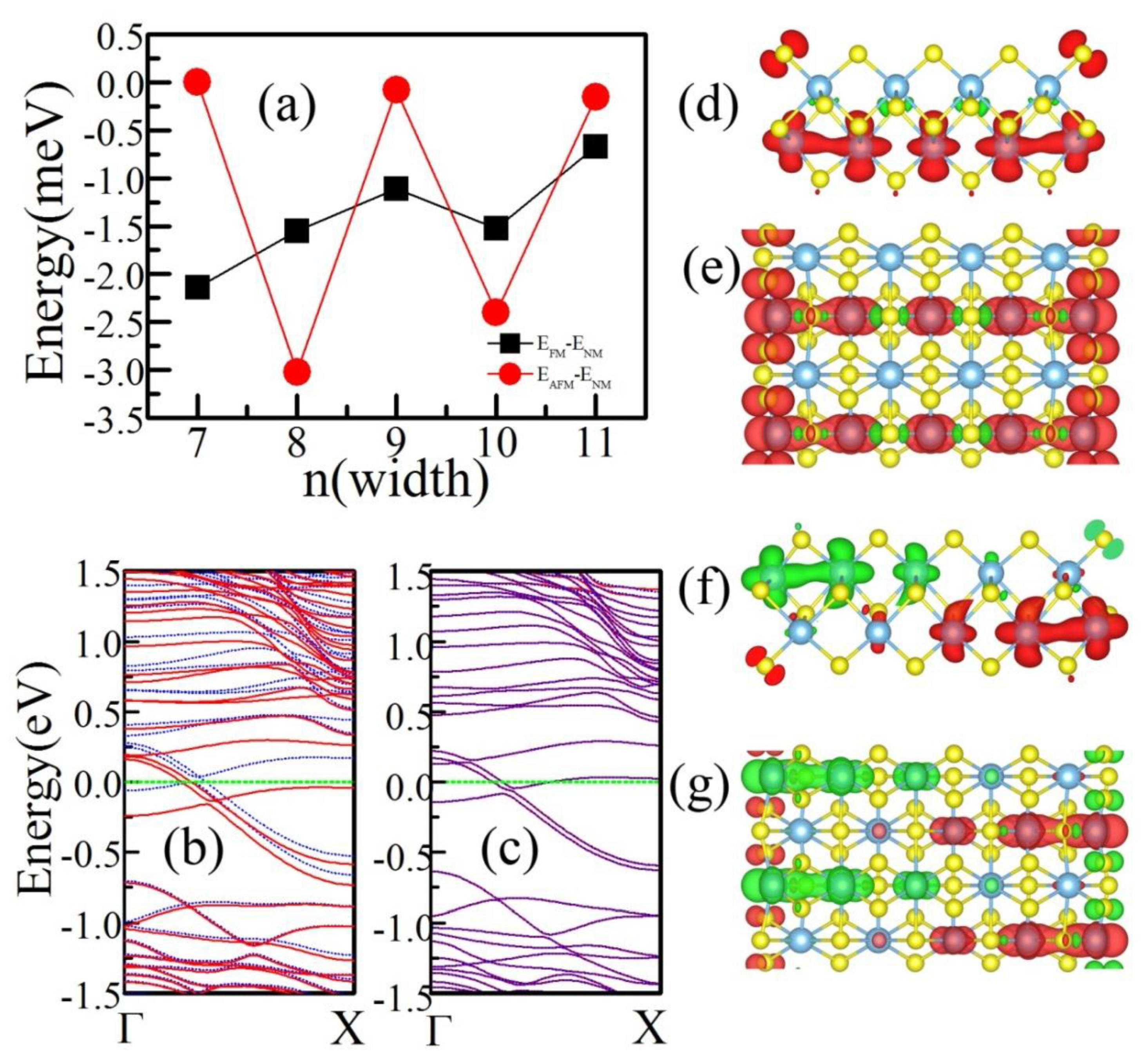
To explore the magnetic ground state of N-a-TiS3 NRs, we set two magnetic configurations, one is a FM arrangement with all magnetic moments in the same direction and the other is an AFM configuration with the magnetic moments of the two edges anti-parallel. From the results of the total energy calculation, we can easily find that the ground state of N-a-TiS3 NRs are not all FM which is different from the previous theoretical results [31]. The magnetic ground state varies as the width changes. Figure 3a shows that the energy difference between the magnetic state and nonmagnetic state, one can easily see that when N is odd, the ground state is FM, meanwhile N is even, the ground state is AFM. This width-dependent magnetic ground state is different from other 2D material NRs like black phosphorus [23].
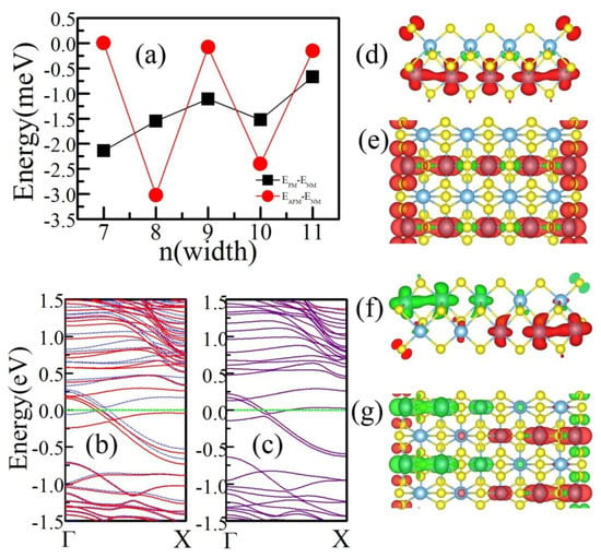
Figure 3.
(a) The energy of magnetic ground state changes as the width of a-TiS3 NR. (b) The spin-polarized band structure of the FM ground state of 9-a-TiS3 NR, red lines (blue dashed lines) indicate spin up (down) component. (c) The spin-polarized band structure of AFM ground state of 10-a-TiS3, red lines (blue dashed lines) denote spin up (down) component. (d) and (e) are spin density of FM state of 9-a-TiS3 NR, (d) is the side view from the period direction of a-TiS3 NR and (e) is the top view. (f) and (g) are the spin density of the AFM state of 10-a-TiS3 NR, (f) is side view from the period direction of 10-a-TiS3 NR and (g) is the top view.
Our calculations also reveal that all N-a-TiS3 NRs have metallic behavior with bands crossing the Fermi level. The electronic band dispersion of ground magnetic states of 9-a-TiS3 NR and 10-a-TiS3NR are shown in Figure 3b,c, respectively. For FM ground state of 9-a-TiS3, there is a spin split near the Fermi level. The total magnetic moment of the unit cell is 0.86 μB which is consistent with the previous calculation [31]. Due to the AFM ground state, two spin components of 10-a-TiS3 are exactly overlapped indicating a perfect AFM state. We also checked the effect of SOC, and we found that the SOC does not change the magnetic ground states of N-a-TiS3 NRs, due to the small SOC effect in light elements.
To get further insight into the spin polarization in a-TiS3 NRs, we also calculated the spin density, which is the difference between spin-up and spin-down channels, and show them in Figure 3d–g. Figure 3d,e are the spin density of FM 9-a-TiS3 NR. The magnetic moment is mainly located on edge S and edge Ti atoms; in addition, the magnetic moment is still located in Ti atoms in the TiS3 chain whose terminal atoms are Ti atom. The magnetic moment decreases from 0.144 μB (edge Ti atom) to 0.131 μB (center Ti atom). The distribution of magnetic moment also indicates the strong hybridization between Ti atoms. Figure 3f,g are the spin density of 10-a-TiS3 NR in AFM ground state. The magnetic moment is mainly located at edge S atoms and Ti atoms. Due to the strong hybridization between Ti atoms in the same TiS3 chain, magnetic moments turn to zero gradually from the terminal Ti to center one.
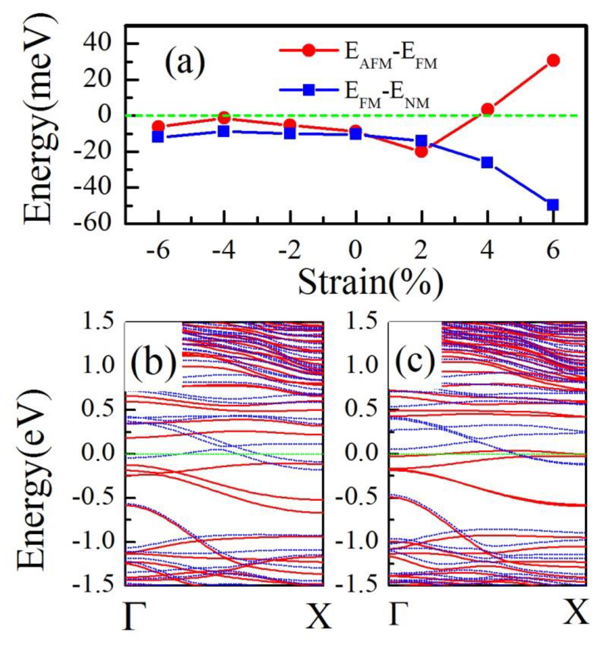
As is well known, the edge states usually are sensitive to strain, doping, and the external field. Here we focused on the effect of strain on the edge states. A uniaxial strain varying from −6% to 6% was applied to investigate the magnetic and electronic properties. The energy differences between FM and nonmagnetic/AFM states of 9-a-TiS3 NR (10-a-TiS3 NR) are shown in Figure 4a. We found that for both 9 and 10-a-TiS3 NR, the compressive strains have a small effect on the magnetic ground state. Although the FM ground state is not changed by tensile strain, the electronic structure had a dramatic change. We calculated the band structure of 9-a-TiS3 NR under the various strains, and found that when a tensile strain as large as 6%, FM 9-a-TiS3 NR become a half metal. The band structure of 9-a-TiS3 NR under 6% tensile strain is plotted in Figure 4b with the red lines denoting the spin up component and blue dashed lines denoting the spin down component. We can clearly see that the spin-up component opens an indirect band gap about 0.2 eV while three spin-down bands cross Fermi energy indicating metal property. The energy difference between AFM and FM show that there is an AFM-FM phase transition of 10-a-TiS3 NR under a 4% tensile strain. We also plotted the band structure of 10-a-TiS3 NR under the 6% tensile strain, a large spin-split around Fermi energy shows the FM property.
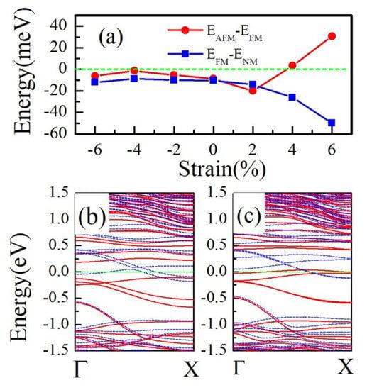
Figure 4.
(a) Energy difference between nonmagnetic (ENM)/anti-ferromagnetic (EAFM) and ferromagnetic (EFM) as a function of strain. (b) The spin-polarized band structure of 9-a-TiS3 NR under 6% tensile strain. (c) The spin-polarized band structure of 10-a-TiS3 NR under 6% tensile strain.
4. Conclusions
In summary, we investigated the electronic and magnetic properties of TiS3 NRs and strain effect by first-principles calculations. Our results reveal that b-TiS3 NRs are non-magnetic semiconductors consistent with previous results. However, the magnetic ground states of N-a-TiS3 NRs are strongly dependent on the width of NRs. When N is an (even) odd number, N-a-TiS3 NRs are (anti-)ferromagnetic metals. The strain effect is also investigated. The compressive strain has little effect on the electronic and magnetic properties of 9(10)-a-TiS3 NRs. On the contrary, a 6% tensile strain will tune 9-a-TiS3 NR from a FM metal into a half metal while a 4% tensile strain cause a AFM-FM phase transition of 10-a-TiS3 NR. Our findings make the N-a-TiS3 NRs promising spintronic devices.
Author Contributions
S.L. performed the calculations; Y.D. interpreted the numerical results and wrote the paper.
Funding
The authors gratefully acknowledge support from the Jiangsu Province Science Foundation for Youth (Grant No. BK20170821) and National Science Foundation of China for Youth (Grant No. 11804160).
Conflicts of Interest
The authors declare no conflicts of interest.
References
- Dahal, B.R.; Dulal, R.P.; Pegg, I.L.; Philip, J. Electrical transport and magnetic properties of cobalt telluride nanostructures. J. Vac. Sci. Technol. B 2016, 34, 051801. [Google Scholar] [CrossRef]
- Dulal, R.P.; Dahal, B.R.; Forbes, A.; Bhattarai, N.; Pegg, I.L.; Philip, J. Ferromagnetism in Fe2XrAl nanowires. J. Vac. Sci. Technol. B 2018, 36, 022902. [Google Scholar] [CrossRef]
- Liang, D.; DeGrave, J.P.; Stolt, M.J.; Tokura, Y.; Jin, S. Current-driven dynamics of skyrmions stabilized in MnSi nanowires revealed by topological Hall effect. Nat. Commun. 2015, 6, 8217. [Google Scholar] [CrossRef] [PubMed]
- Stano, M.; Fruchart, O. Magnetic Nanowires and Nanotubes. Handb. Magn. Mater. 2018, 27, 155–267. [Google Scholar]
- Novoselov, K.S.; Geim, A.K.; Morozov, S.V.; Jiang, D.; Zhang, Y.; Dubonos, S.V.; Grigorieva, I.V.; Firsov, A.A. Electric Field Effect in Atomically Thin Carbon Films. Science 2004, 306, 666. [Google Scholar] [CrossRef]
- Zhang, Y.; Tan, Y.; Stormer, H.; Kim, P. Experimental observation of the quantum Hall effect and Berry’s phase in graphene. Nature 2005, 438, 201. [Google Scholar] [CrossRef]
- Xia, Y.; Yang, P.; Sun, Y.; Wu, Y.; Mayers, B.; Gates, B.; Yin, Y.; Kim, F.; Yan, H. Mediated Synthesis of Fe2O3 Nanorods. Adv. Mater. 2003, 15, 353. [Google Scholar] [CrossRef]
- Barone, V.; Hod, O.; Scuseria, G.E. Electronic Structure and Stability of Semiconducting Graphene Nanoribbons. Nano Lett. 2006, 6, 2748–2754. [Google Scholar] [CrossRef]
- Son, Y.-W.; Cohen, M.L.; Louie, S.G. Energy gaps in graphene nanoribbons. Phys. Rev. Lett. 2006, 97, 216803. [Google Scholar] [CrossRef]
- Han, M.Y.; Özyilmaz, B.; Zhang, Y.; Kim, P. Energy Band-Gap Engineering of Graphene Nanoribbons. Phys. Rev. Lett. 2007, 98, 206805. [Google Scholar] [CrossRef]
- Li, X.L.; Wang, X.R.; Zhang, L.; Lee, S.W.; Dai, H.J. Chemically derived, ultrasmooth graphene nanoribbon semiconductors. Science 2008, 319, 1229–1232. [Google Scholar] [CrossRef] [PubMed]
- Fujita, M.; Wakabayashi, K.; Nakada, K.; Kusakabe, K.J. Physical Peculiar localized state at zigzag graphite edge. Soc. Jpn. 1996, 65, 1920–1923. [Google Scholar] [CrossRef]
- Nakada, K.; Fujita, M.; Dresselhaus, G.; Dresselhaus, M.S. Edge state in graphene ribbons: Nanometer size effect and edge shape dependence. Phys. Rev. B 1996, 54, 17954–17961. [Google Scholar] [CrossRef] [PubMed]
- Son, Y.-W.; Cohen, M.L.; Louie, S.G. Half-metallic graphene nanoribbons. Nature 2006, 444, 347–349. [Google Scholar] [CrossRef] [PubMed]
- Hod, O.; Barone, V.; Peralta, J.E.; Scuseria, G.E. Enhanced half-metallicity in edge-oxidized zigzag graphene nanoribbons. Nano Lett. 2007, 7, 2295–2299. [Google Scholar] [CrossRef]
- Kan, E.J.; Li, Z.Y.; Yang, J.L.; Hou, J.G. Half-metallicity in edge-modified zigzag graphene nanoribbons. J. Am. Chem. Soc. 2008, 130, 4224–4225. [Google Scholar] [CrossRef] [PubMed]
- Li, Y.F.; Zhou, Z.; Shen, P.W.; Chen, Z.F. Spin Gapless Semiconductor−Metal−Half-Metal Properties in Nitrogen-Doped Zigzag Graphene Nanoribbons. ACS Nano 2009, 3, 1952–1958. [Google Scholar] [CrossRef]
- Dutta, S.; Pati, S.K. Half-metallicity in undoped and boron doped graphene nanoribbons in the presence of semilocal exchange-correlation interactions. J. Phys. Chem. B 2008, 112, 1333–1335. [Google Scholar] [CrossRef]
- Lin, X.; Ni, J. Half-metallicity in graphene nanoribbons with topological line defects. Phys. Rev. B 2011, 84, 075461. [Google Scholar] [CrossRef]
- Barone, V.; Peralta, J.E. Magnetic boron nitride nanoribbons with tunable electronic properties. Nano Lett. 2008, 8, 2210–2214. [Google Scholar] [CrossRef]
- Li, Y.F.; Zhou, Z.; Zhang, S.B.; Chen, Z.F. MoS2 Nanoribbons: High Stability and Unusual Electronic and Magnetic Properties. J. Am. Chem. Soc. 2008, 130, 16739. [Google Scholar] [CrossRef] [PubMed]
- Hu, T.; Hong, J. Electronic structure and magnetic properties of zigzag blue phosphorene nanoribbons. J. Appl. Phys. 2005, 118, 054301. [Google Scholar] [CrossRef]
- Du, Y.P.; Liu, H.M.; Xu, B.; Sheng, L.; Yin, J.; Duan, C.G.; Wan, X.G. Unexpected Magnetic Semiconductor Behavior in Zigzag Phosphorene Nanoribbons Driven by Half-Filled One Dimensional Band. Sci. Rep. 2015, 5, 8921. [Google Scholar] [CrossRef] [PubMed]
- Botello-Méndez, A.R.; Loópez-Uriías, F.; Terrones, M.; Terrones, H. Magnetic Behavior in Zinc Oxide Zigzag Nanoribbons. Nano Lett. 2008, 8, 1562. [Google Scholar]
- Island, J.O.; Buscema, M.; Barawi, M.; Clamagirand, J.M.; Ares, J.R.; Sanchez, C.; Ferrer, I.J.; Steele, G.A.; van der Zant, H.S.J.; Castellanos-Gomez, A. Ultrahigh Photoresponse of Few-Layer TiS3 Nanoribbon Transistors. Adv. Opt. Mater. 2014, 2, 641–645. [Google Scholar] [CrossRef]
- Island, J.O.; Buscema, M.; Biele, R.; Almazan, A.; Clamagirand, J.M.; Ares, J.R.; Sanchez, C.; van der Zant, H.S.; Álvarez, J.V.; D’Agosta, R.; et al. TiS3 Transistors with Tailored Morphology and Electrical Properties. Adv. Mater. 2015, 27, 2595–2601. [Google Scholar] [CrossRef]
- Pawbake, A.S.; Island, J.O.; Flores, E.; Ares, J.R.; Sanchez, C.; Ferrer, I.J.; Jadkar, S.R.; van der Zant, H.S.; Castellanos-Gomez, A.; Late, D.J. Temperature-Dependent Raman Spectroscopy of Titanium Trisulfide (TiS3) Nanoribbons and Nanosheets. ACS Appl. Mater. Interfaces 2015, 7, 24185–24190. [Google Scholar] [CrossRef]
- Molina-Mendoza, A.J.; Barawi, M.; Biele, R.; Flores, E.; Ares, J.R.; Sanchez, C.; Rubio-Bollinger, G.; Agrat, N.; D’Agosta, R.; Ferrer, I.J.; et al. Electronic Bandgap and Exciton Binding Energy of Layered Semiconductor TiS3. Adv. Electron. Mater. 2015, 1, 1500126. [Google Scholar] [CrossRef]
- Dai, J.; Zeng, X.C. Titanium trisulfide monolayer: Theoretical prediction of a new direct-gap semiconductor with high and anisotropic carrier mobility. Angew. Chem.-Int. Ed. 2015, 54, 7572. [Google Scholar] [CrossRef]
- Kang, J.; Wang, L.W. Robust band gap of TiS3 nanofilms. Phys. Chem. Chem. Phys. 2016, 18, 14805. [Google Scholar] [CrossRef]
- Kang, J.; Sahin, H.; Ozaydin, D.; Senger, R.T.; Peeters, F.M. TiS3 nanoribbons: Width-independent band gap and strain-tunable electronic properties. Phys. Rev. B 2015, 92, 075413. [Google Scholar] [CrossRef]
- Ce, H.; Zhang, E.Z.; Yuan, X.; Wang, W.Y.; Liu, Y.W.; Zhang, C.; Ling, J.W.; Liu, S.S.; Xiu, F.X. Tunable charge density wave in TiS3 nanoribbons. Chin. Phys. B 2017, 26, 067302. [Google Scholar] [CrossRef]
- Lipatov, A.; Loes, M.J.; Lu, H.D.; Dai, J.; Patoka, P.; Vorobeva, N.S.; Muratov, D.S.; Ulrich, G.; Kästner, B.; Hoehl, A.; et al. Quasi-1D TiS3 Nanoribbons: Mechanical Exfoliation and Thickness-Dependent Raman Spectroscopy. ACS Nano 2018, 12, 12713–12720. [Google Scholar] [CrossRef] [PubMed]
- Kresse, G.; Hafner, J. Ab initio molecular dynamics for liquid metals. Phys. Rev. B 1993, 47, 558(R). [Google Scholar] [CrossRef] [PubMed]
- Kresse, G.; Furthmuller, J. Efficient iterative schemes for ab initio total-energy calculations using a plane-wave basis set. Phys. Rev. B 1996, 54, 11169. [Google Scholar] [CrossRef]
- Perdew, J.P.; Burke, K.; Ernerhof, M. Generalized Gradient Approximation Made Simple. Phys. Rev. Lett. 1997, 77, 3865. [Google Scholar] [CrossRef]
- Furuseth, S.; Brattas, L.; Kjekshus, A. Crystal Structures of TiS3, ZrS3, ZrSe3, ZrTe3, HfS3 and HfSe3. Acta Chem. Scand. 1975, 29, 623. [Google Scholar]
- Stoner, E.C. Collective electron specific heat and spin paramgnetism in metals. Proc. R. Soc. A 1936, 154, 656. [Google Scholar]
© 2019 by the authors. Licensee MDPI, Basel, Switzerland. This article is an open access article distributed under the terms and conditions of the Creative Commons Attribution (CC BY) license (http://creativecommons.org/licenses/by/4.0/).

