Trueness of the Inner Surface of Monolithic Crowns Fabricated by Milling of a Fully Sintered (Y, Nb)-TZP Block in Chairside CAD–CAM System for Single-visit Dentistry


Abstract
:1. Introduction
2. Materials and Methods
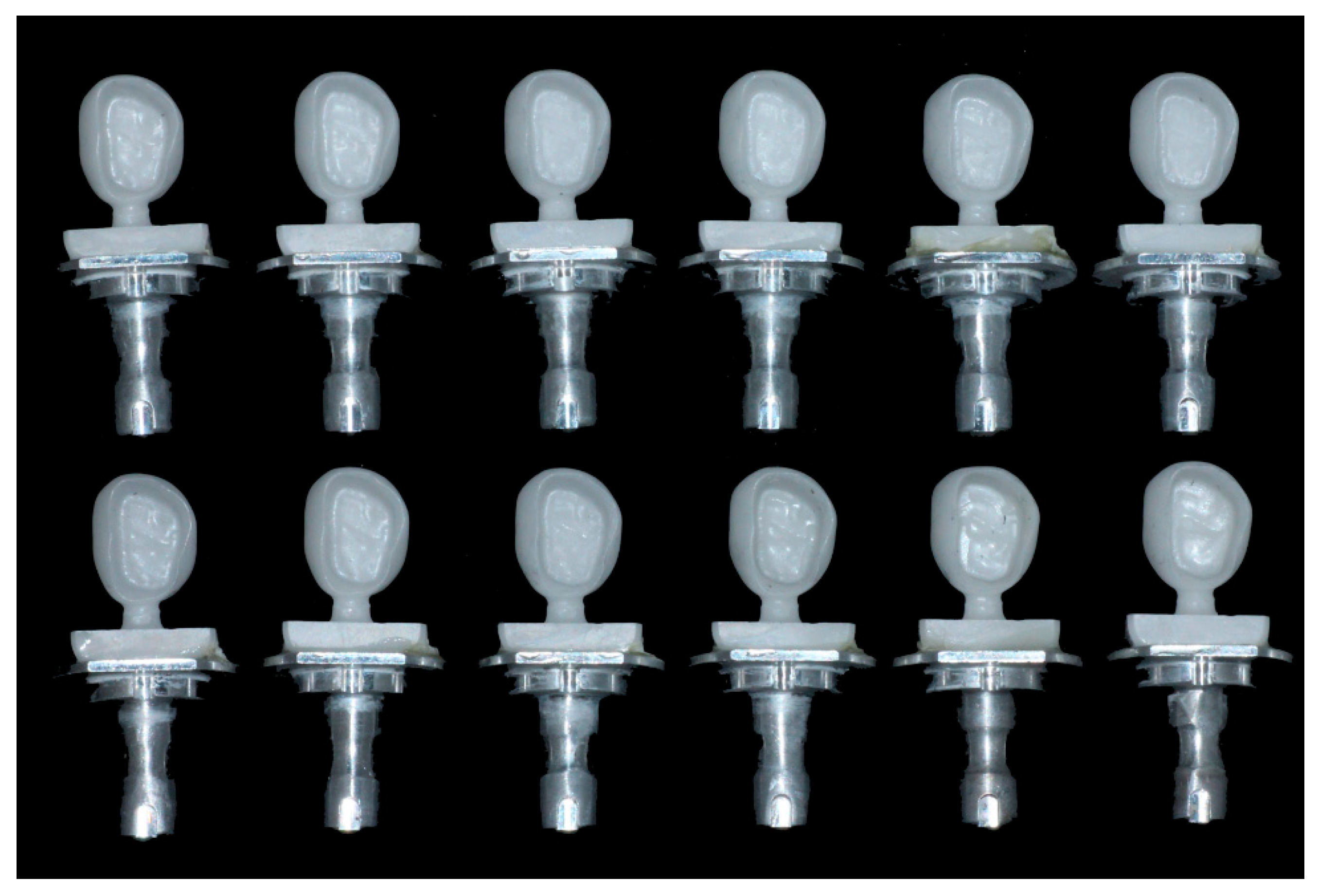
2.1. Working Cast Preparation
2.2. Full-Contour Crown Fabrication
2.3. Time Analysis
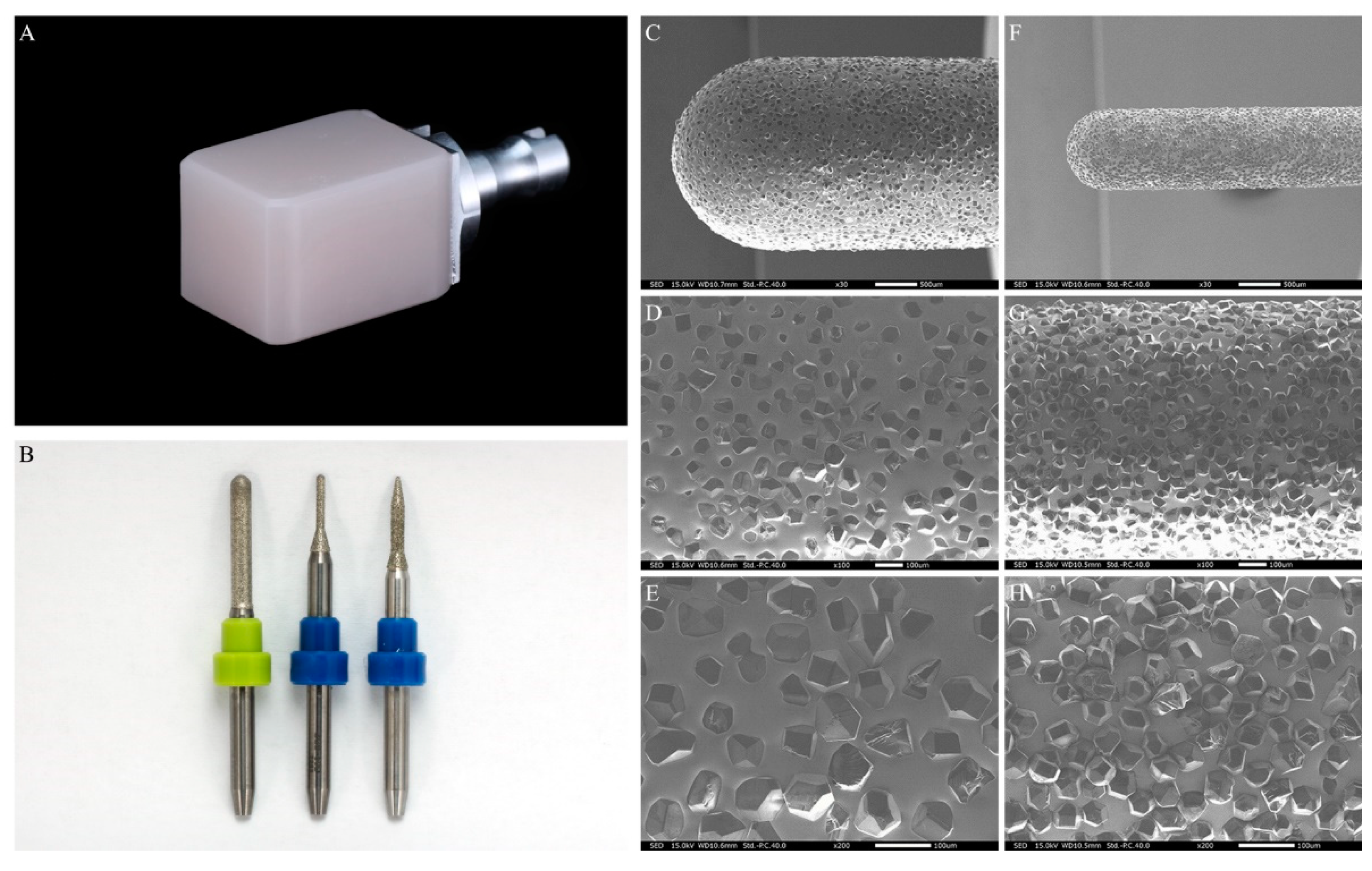
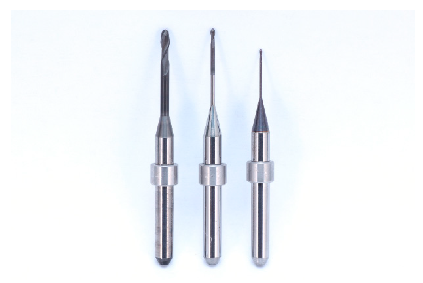
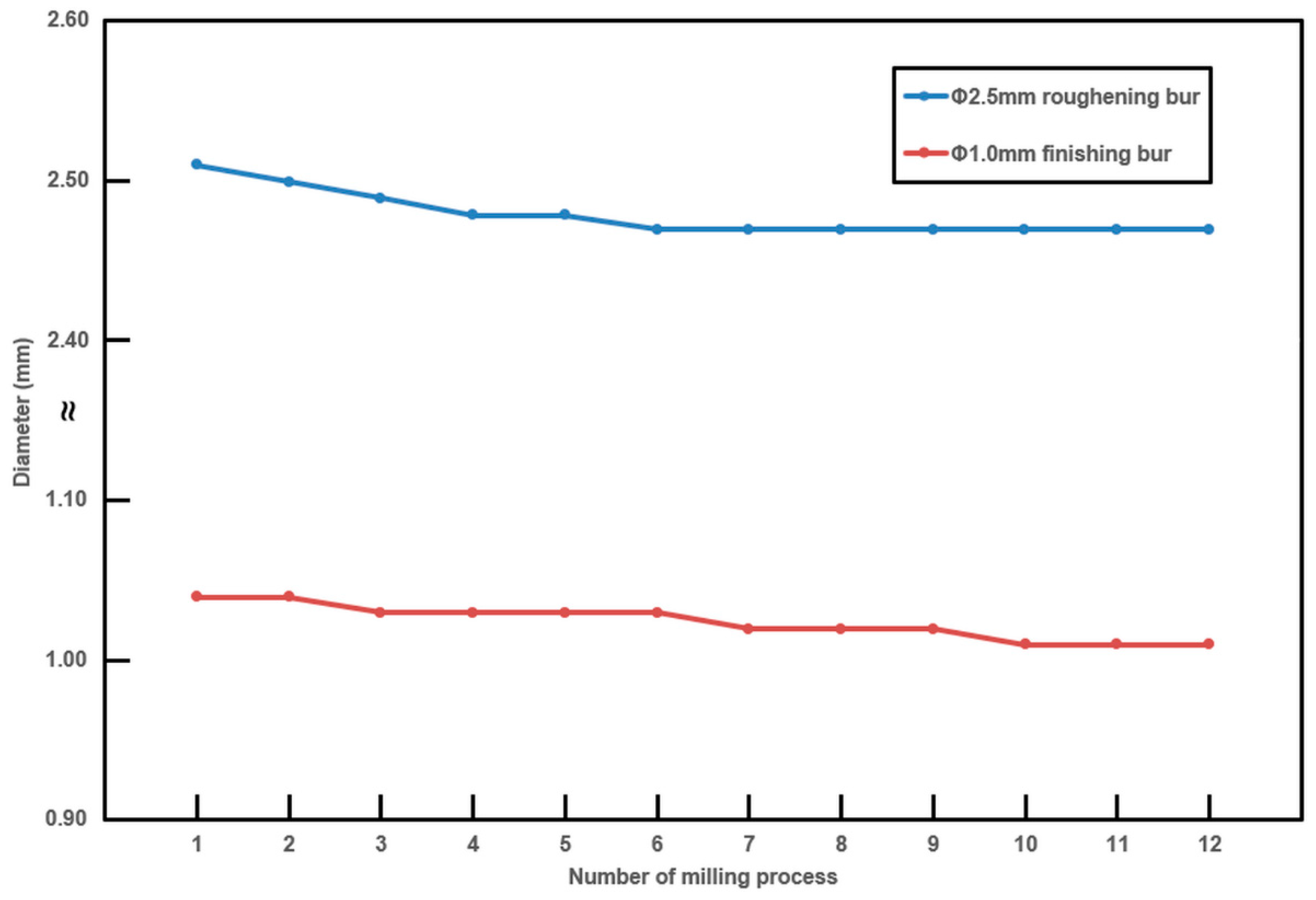
2.4. Tool Wear Analysis
2.5. Trueness Analysis
3. Results
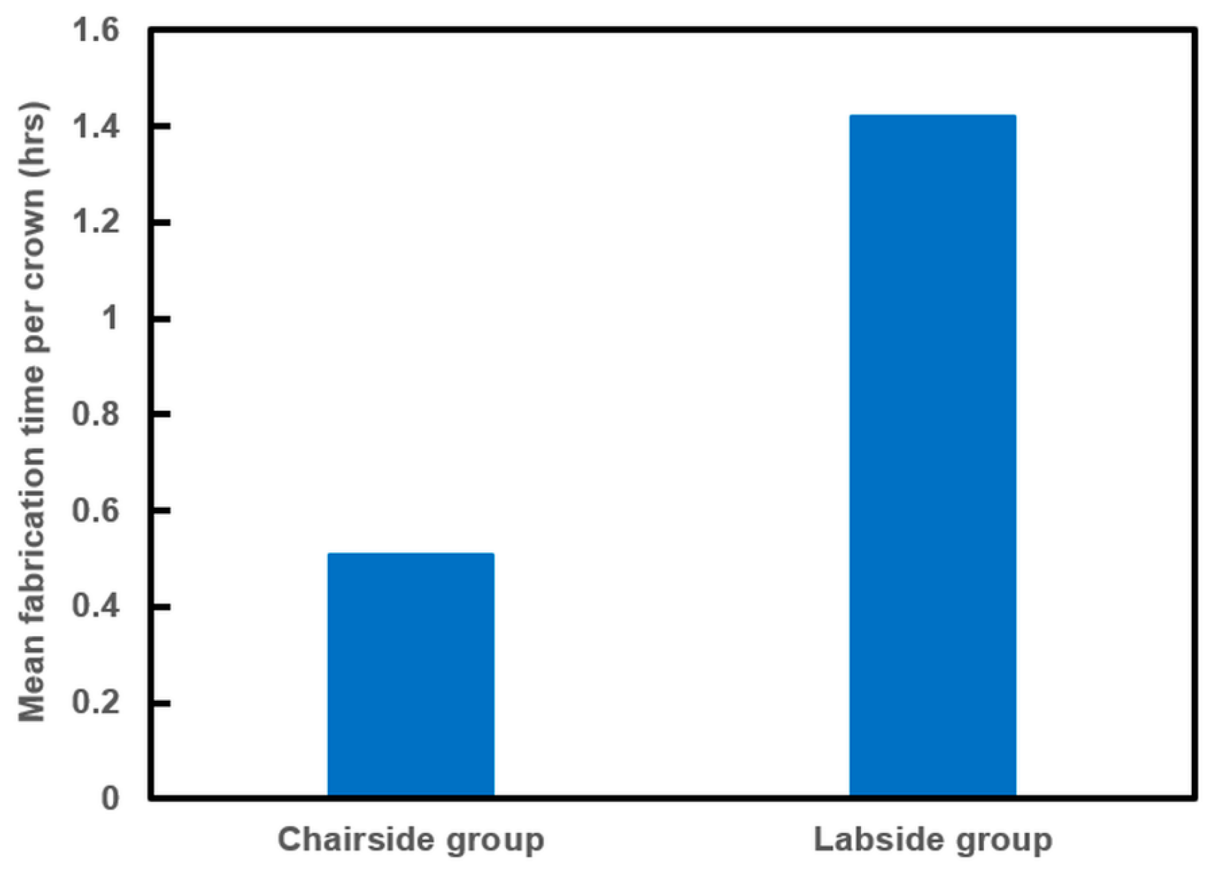
3.1. Time Analysis
3.2. Tool Wear Analysis
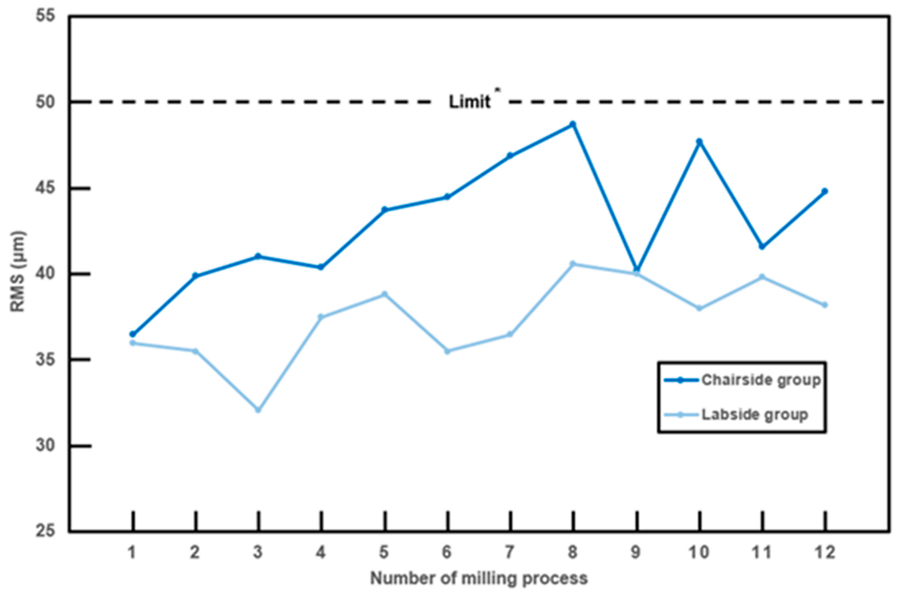
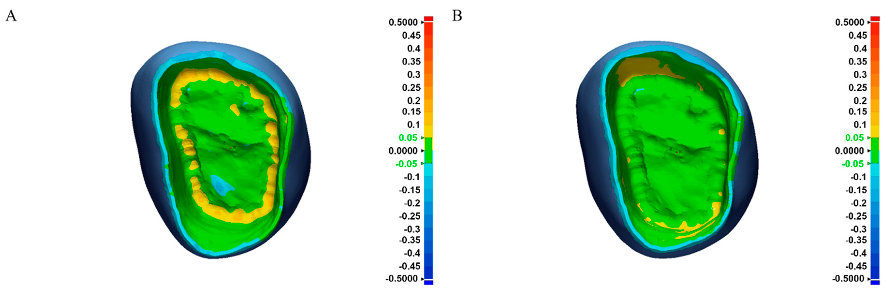
3.3. Trueness Analysis
4. Discussion
5. Conclusions
- Single-visit zirconia crown restoration that meets the clinical trueness requirement can be realized via milling a fully sintered (Y,Nb)-TZP block with a chairside CAD–CAM system.
- The trueness outcomes of both Chairside and Labside groups were clinically acceptable, although significantly lower trueness was observed in the Chairside group than in the Labside group.
- The mean fabrication time was 0.52 h for the Chairside group and 1.42 h for the Labside group.
- For the Chairside group, the trueness outcomes of the crowns were all clinically acceptable, even though the diameter of the milling tools decreased.
Author Contributions
Funding
Acknowledgments
Conflicts of Interest
References
- Sannino, G.; Germano, F.; Arcuri, L.; Bigelli, E.; Arcuri, C.; Barlattani, A. Cerec CAD/CAM chairside system. ORAL Implantol. 2014, 7, 57. [Google Scholar] [PubMed]
- Kaizer, M.R.; Gierthmuehlen, P.C.; Dos Santos, M.B.; Cava, S.S.; Zhang, Y. Speed sintering translucent zirconia for chairside one–visit dental restorations: Optical, mechanical, and wear characteristics. Ceram. Int. 2017, 43, 10999–11005. [Google Scholar] [CrossRef] [PubMed]
- Jansen, J.U.; Lumkemann, N.; Letz, I.; Pfefferle, R.; Sener, B.; Stawarczyk, B. Impact of high–speed sintering on translucency, phase content, grain sizes, and flexural strength of 3Y–TZP and 4Y–TZP zirconia materials. J. Prosthet. Dent. 2019. [Google Scholar] [CrossRef]
- Wiedhahn, K.; Fritzsche, G.; Wiedhahn, C.; Schenk, O. Zirconia crowns–the new standard for single–visit dentistry? Inter. J. Comput. Dent. 2016, 19, 9–26. [Google Scholar]
- Wang, W.; Yu, H.; Liu, Y.; Jiang, X.; Gao, B. Trueness analysis of zirconia crowns fabricated with 3–dimensional printing. J. Prosthet. Dent. 2019, 121, 285–291. [Google Scholar] [CrossRef]
- Abduo, J.; Lyons, K.; Swain, M. Fit of zirconia fixed partial denture: A systematic review. J. Oral. Rehabil. 2010, 37, 866–876. [Google Scholar] [CrossRef] [PubMed]
- Sinmazisik, G.; Demirbas, B.; Tarcin, B. Influence of dentin and core porcelain thickness on the color of fully sintered zirconia ceramic restorations. J. Prosthet. Dent. 2014, 111, 142–149. [Google Scholar] [CrossRef]
- Edwards Rezende, C.E.; Sanches Borges, A.F.; Macedo, R.M.; Rubo, J.H.; Griggs, J.A. Dimensional changes from the sintering process and fit of Y–TZP copings: Micro–CT analysis. Dent. Mater. 2017, 33, e405–e413. [Google Scholar] [CrossRef]
- Hatanaka, G.R.; Polli, G.S.; Fais, L.M.; dos SN Reis, J.M.; Pinelli, L.A. Zirconia changes after grinding and regeneration firing. J. Prosthet. Dent. 2017, 118, 61–68. [Google Scholar] [CrossRef]
- Denry, I.; Kelly, J.R. State of the art of zirconia for dental applications. Dent Mater 2008, 24, 299–307. [Google Scholar] [CrossRef]
- Yener, E.S.; Özcan, M.; Kazazoğlu, E. The effect of glazing on the biaxial flexural strength of different zirconia core materials. Acta Odontol. Latinoam. 2011, 24, 133–140. [Google Scholar] [PubMed]
- Guazzato, M.; Quach, L.; Albakry, M.; Swain, M.V. Influence of surface and heat treatments on the flexural strength of Y–TZP dental ceramic. J. Dent. 2005, 33, 9–18. [Google Scholar] [CrossRef] [PubMed]
- Kirsch, C.; Ender, A.; Attin, T.; Mehl, A. Trueness of four different milling procedures used in dental CAD/CAM systems. Clin. Oral. Investig. 2017, 21, 551–558. [Google Scholar] [CrossRef] [PubMed]
- International Organization for Standardization. ISO–5725–2. Accuracy (Trueness and Precision) of Measurement Methods and Results–Part 2: Basic Method for the Determination of Repeatability and Reproducibility of A Standard Measurement Method; ISO: Geneva, Switzerland, 1994; Available online: http://www.iso.org/iso/store.htm (accessed on 22 December 1994).
- Kim, C.M.; Kim, S.R.; Kim, J.H.; Kim, H.Y.; Kim, W.C. Trueness of milled prostheses according to number of ball–end mill burs. J. Prosthet. Dent. 2016, 115, 624–629. [Google Scholar] [CrossRef] [PubMed]
- Schonberger, J.; Erdelt, K.J.; Baumer, D.; Beuer, F. Evaluation of Two Protocols to Measure the Accuracy of Fixed Dental Prostheses: An In Vitro Study. J. Prosthodont. 2019, 28, e599–e603. [Google Scholar] [CrossRef] [PubMed]
- International Organization for Standardization. ISO–12836. Dentistrydigitizing Devices for CAD/CAM Systems for Indirect Dental Restorations–Test Methods for Assessing Accuracy; ISO: Geneva, Switzerland, 2015; Available online: http://www.iso.org/iso/store.htm (accessed on 1 July 2015).
- Peters, M.C.R.B.; Delong, R.; Pintado, M.R.; Pallesen, U.; Qvist, V.; Douglas, W.H. Comparison of two measurement techniques for clinical wear. J. Dent. 1999, 27, 479–485. [Google Scholar] [CrossRef]
- Bosch, G.; Ender, A.; Mehl, A. A 3–dimensional accuracy analysis of chairside CAD/CAM milling processes. J. Prosthet. Dent. 2014, 112, 1425–1431. [Google Scholar] [CrossRef]
- Moldovan, O.; Luthardt, R.G.; Corcodel, N.; Rudolph, H. Three–dimensional fit of CAD/CAM–made zirconia copings. Dent. Mater. 2011, 27, 1273–1278. [Google Scholar] [CrossRef]
- Roperto, R.C.; Lopes, F.C.; Porto, T.S.; Teich, S.; Rizzante, F.A.P.; Gutmacher, Z.; Sousa–Neto, M.D. CAD/CAM diamond tool wear. Quintessence Int. 2018, 49, 781–786. [Google Scholar]
- Lebon, N.; Tapie, L.; Vennat, E.; Mawussi, B. Influence of CAD/CAM tool and material on tool wear and roughness of dental prostheses after milling. J. Prosthet. Dent. 2015, 114, 236–247. [Google Scholar] [CrossRef]
- Schaefer, O.; Watts, D.C.; Sigusch, B.W.; Kuepper, H.; Guentsch, A. Marginal and internal fit of pressed lithium disilicate partial crowns in vitro: A three–dimensional analysis of accuracy and reproducibility. Dent. Mater. 2012, 28, 320–326. [Google Scholar] [CrossRef] [PubMed]
- Kang, S.Y.; Park, J.H.; Kim, J.H.; Kim, W.C. Accuracy of provisional crowns made using stereolithography apparatus and subtractive technique. J. Adv. Prosthodont. 2018, 10, 354–360. [Google Scholar] [CrossRef] [PubMed]
- Alghazzawi, T.F. Advancements in CAD/CAM technology: Options for practical implementation. J. Prosthodont. Res. 2016, 60, 72–84. [Google Scholar] [CrossRef] [PubMed]
- Boitelle, P.; Tapie, L.; Mawussi, B.; Fromentin, O. Evaluation of the marginal fit of CAD–CAM zirconia copings: Comparison of 2D and 3D measurement methods. J. Prosthet. Dent. 2018, 119, 75–81. [Google Scholar] [CrossRef] [PubMed]
- Boitelle, P.; Mawussi, B.; Tapie, L.; Fromentin, O. A systematic review of CAD/CAM fit restoration evaluations. J. Oral. Rehabil. 2014, 41, 853–874. [Google Scholar] [CrossRef] [PubMed]
- Ohkuma, K.; Kameda, T.; Terada, K. Five–axis laser milling system that realizes more accurate zirconia CAD/CAM crowns by direct milling from fully sintered blocks. Dent. Mater. J. 2019, 38, 52–60. [Google Scholar] [CrossRef] [PubMed]
- International Organization of Standardization. ISO/TR 18845 Dentistry —Test methods for machining accuracy of computer–aided milling machines. 2016. [Google Scholar]
- Pagano, S.; Moretti, M.; Marsili, R.; Ricci, A.; Barraco, G.; Cianetti, S. Evaluation of the accuracy of four digital methods by linear and volumetric analysis of dental impressions. Materials 2019, 12, 1958. [Google Scholar] [CrossRef]
- Mohammadi–Bassir, M.; Babasafari, M.; Rezvani, M.B.; Jamshidian, M. Effect of coarse grinding, overglazing, and 2 polishing systems on the flexural strength, surface roughness, and phase transformation of yttrium–stabilized tetragonal zirconia. J. Prosthet. Dent. 2017, 118, 658–665. [Google Scholar] [CrossRef] [PubMed]

| Time | Chairside Group |
|---|---|
| Flexural strength (MPa) | 760 |
| Toughness (MPa·m1/2) | 7.4 |
| Hardness (GPa) | 8.6 |
| Machinability (m1/2 × 103) (defined as the ratio of fracture toughness/hardness) | 0.86 |
| Transmittance (%) | 58 |
| Time | Chairside Group | Labside Group |
|---|---|---|
| Milling time (h) | 6.2 | 5.0 |
| Sintering time (h) | - | 12.0 |
| Total fabrication time (h) | 6.2 | 17.0 |
| Mean fabrication time per crown (h) | 0.52 | 1.42 |
| Area | Chairside Group (μm) | Labside Group (μm) | p | ||
|---|---|---|---|---|---|
| RMS ± SD | 95% CI | RMS ± SD | 95% CI | ||
| Inner | 43.0 ± 3.67 | 40.7–45.3 | 37.4 ± 2.41 | 35.8–38.9 | <0.001 |
© 2019 by the authors. Licensee MDPI, Basel, Switzerland. This article is an open access article distributed under the terms and conditions of the Creative Commons Attribution (CC BY) license (http://creativecommons.org/licenses/by/4.0/).
Share and Cite
Cho, J.-H.; Yoon, H.-I.; Han, J.-S.; Kim, D.-J. Trueness of the Inner Surface of Monolithic Crowns Fabricated by Milling of a Fully Sintered (Y, Nb)-TZP Block in Chairside CAD–CAM System for Single-visit Dentistry. Materials 2019, 12, 3253. https://doi.org/10.3390/ma12193253
Cho J-H, Yoon H-I, Han J-S, Kim D-J. Trueness of the Inner Surface of Monolithic Crowns Fabricated by Milling of a Fully Sintered (Y, Nb)-TZP Block in Chairside CAD–CAM System for Single-visit Dentistry. Materials. 2019; 12(19):3253. https://doi.org/10.3390/ma12193253
Chicago/Turabian StyleCho, Jun-Ho, Hyung-In Yoon, Jung-Suk Han, and Dae-Joon Kim. 2019. "Trueness of the Inner Surface of Monolithic Crowns Fabricated by Milling of a Fully Sintered (Y, Nb)-TZP Block in Chairside CAD–CAM System for Single-visit Dentistry" Materials 12, no. 19: 3253. https://doi.org/10.3390/ma12193253
APA StyleCho, J.-H., Yoon, H.-I., Han, J.-S., & Kim, D.-J. (2019). Trueness of the Inner Surface of Monolithic Crowns Fabricated by Milling of a Fully Sintered (Y, Nb)-TZP Block in Chairside CAD–CAM System for Single-visit Dentistry. Materials, 12(19), 3253. https://doi.org/10.3390/ma12193253