A Comparative 3D Finite Element Computational Study of Three Connections

 ,
,  ,
, 

Abstract
1. Introduction
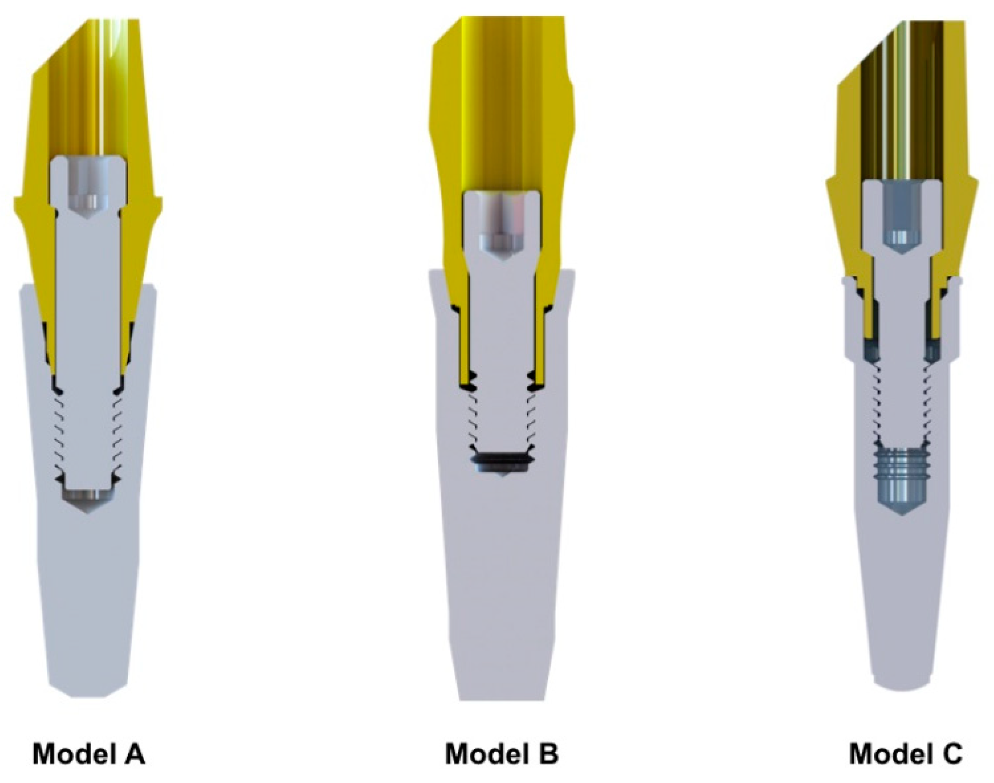
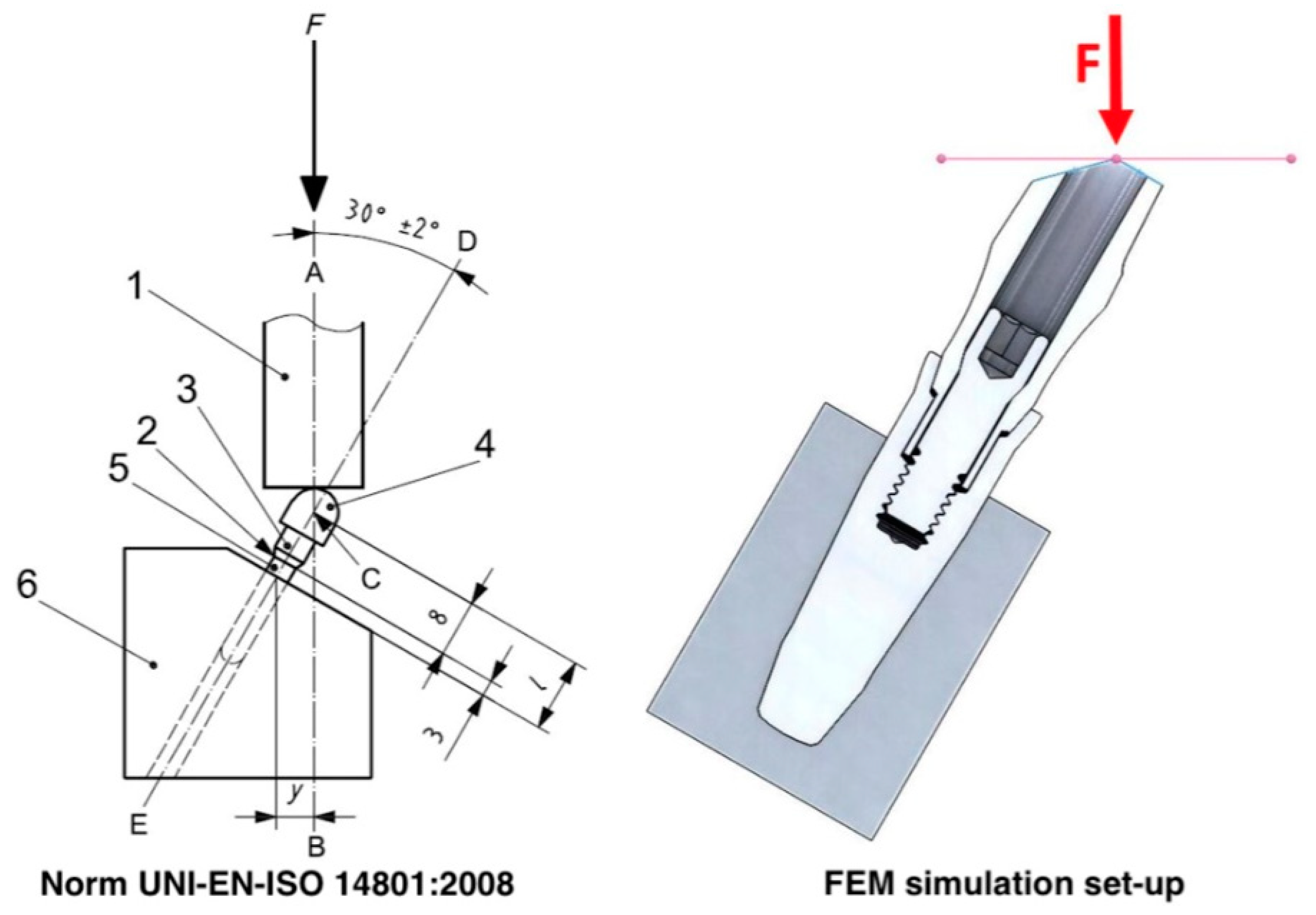
2. Materials and Methods
3. Results
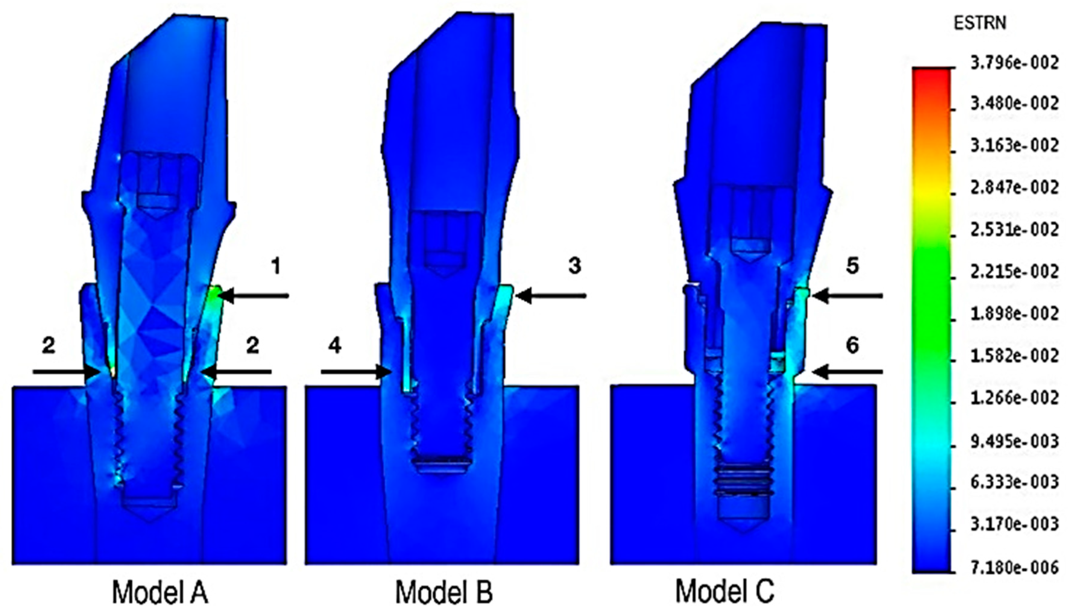
3.1. Strain Map
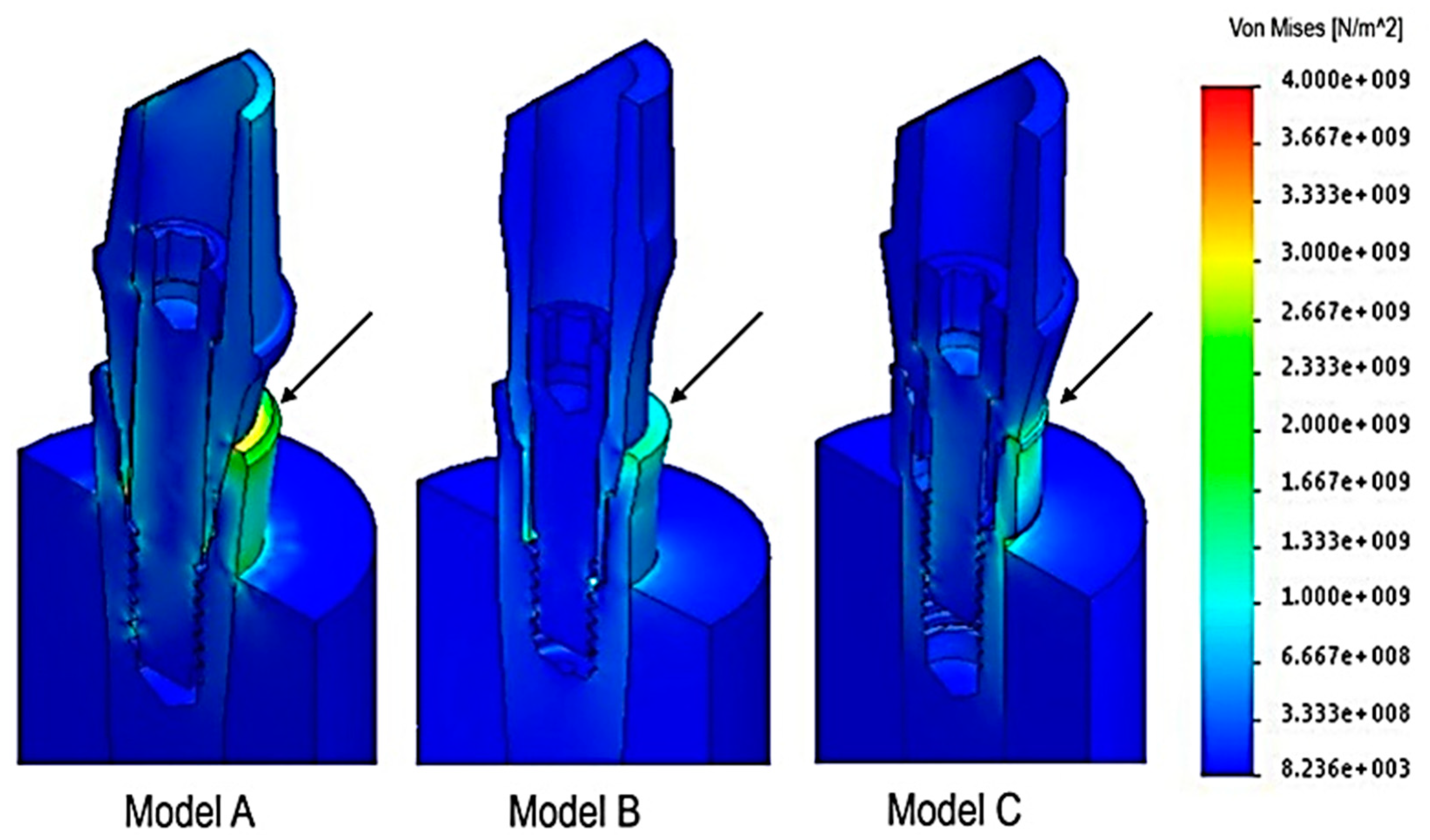
3.2. Stress Analysis
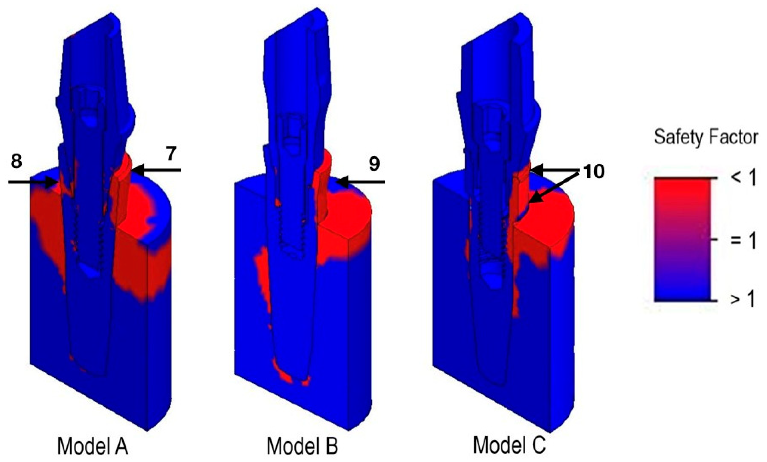
3.3. Safety Factor
3.4. Implant Model Comparison
4. Discussion
5. Conclusions
Author Contributions
Funding
Acknowledgments
Conflicts of Interest
References
- Darcey, J.; Eldridge, D. Fifty Years of Dental Implant Development: A Continuous Evolution. Dent. Hist. 2016, 61, 75–92. [Google Scholar] [PubMed]
- Chrcanovic, B.R. Reasons for failures of oral implants. J. Oral Rehabil. 2014, 41, 443–476. [Google Scholar] [CrossRef] [PubMed]
- Marcián, P.; Wolff, J.; Horáčková, L.; Kaiser, J.; Zikmund, T.; Borák, L. Micro finite element analysis of dental implants under different loading conditions. Comput. Biol. Med. 2018, 96, 157–165. [Google Scholar] [CrossRef]
- Brunski, J.B. In vivo bone response to biomechanical loading at the bone/dental-implant interface. Adv. Dent. Res. 1999, 13, 99–119. [Google Scholar] [CrossRef] [PubMed]
- Lima de Andrade, C.; Carvalho, M.A.; Bordin, D.; da Silva, W.J.; Del Bel Cury, A.A.; Sotto-Maior, B.S. Biomechanical Behavior of the Dental Implant Macrodesign. Int. J. Oral Maxillofac. Implant. 2017, 32, 264–270. [Google Scholar] [CrossRef] [PubMed]
- De Andrade, C.L.; Carvalho, M.A.; Del Bel Cury, A.A.; Sotto-Maior, B.S. Biomechanical Effect of Prosthetic Connection and Implant Body Shape in Low-Quality Bone of Maxillary Posterior Single Implant-Supported Restorations. Int. J. Oral Maxillofac. Implant. 2016, 31, 92–97. [Google Scholar] [CrossRef] [PubMed]
- Yamanishi, Y.; Yamaguchi, S.; Imazato, S.; Nakano, T.; Yatani, H. Effects of the implant design on peri-implant bone stress and abutment micromovement: Three-dimensional finite element analysis of original computer-aided design models. J. Periodontol. 2014, 85, 333–338. [Google Scholar] [CrossRef] [PubMed]
- Wu, A.Y.; Huang, H.L.; Hsu, J.T.; Chee, W. Biomechanical effects of the implant material and implant-abutment interface in immediately loaded small-diameter implants. Clin. Oral Investig. 2014, 18, 1335–1341. [Google Scholar] [CrossRef] [PubMed]
- Qian, L.; Todo, M.; Matsushita, Y.; Koyano, K. Effects of implant diameter, insertion depth and loading angle on stress/strain fields in implant/jawbone systems: Finite element analysis. Int. J. Oral Maxillofac. Implant. 2009, 24, 877–886. [Google Scholar]
- Borie, E.; Orsi, I.A.; de Araujo, C.P. The influence of the connection, length and diameter of an implant on bone biomechanics. Acta Odontol. Scand. 2015, 73, 321–329. [Google Scholar] [CrossRef] [PubMed]
- Duyck, J.; Vandamme, K. The effect of loading on peri-implant bone: A critical review of the literature. J. Oral Rehabil. 2014, 41, 783–794. [Google Scholar] [CrossRef] [PubMed]
- Cervino, G.; Romeo, U.; Lauritano, F.; Bramanti, E.; Fiorillo, L.; D’Amico, C.; Milone, D.; Laino, L.; Campolongo, F.; Rapisarda, S.; et al. Fem and Von Mises Analysis of OSSTEM® Dental Implant Structural Components: Evaluation of Different Direction Dynamic Loads. Open Dent. J. 2018, 12, 219–229. [Google Scholar] [CrossRef] [PubMed]
- Pellizzer, E.P.; Verri, F.R.; Falcón-Antenucci, R.M.; Júnior, J.F.; de Carvalho, P.S.; de Moraes, S.L.; Noritomi, P.Y. Stress analysis in platform-switching implants: A 3-dimensional finite element study. J. Oral Implantol. 2012, 38, 587–594. [Google Scholar] [CrossRef] [PubMed]
- Balik, A.; Karatas, M.O.; Keskin, H. Effects of different abutment connection designs on the stress distribution around five different implants: A 3-dimensional finite element analysis. J. Oral Implantol. 2012, 38, 491–496. [Google Scholar] [CrossRef] [PubMed]
- Cho, S.Y.; Huh, Y.H.; Park, C.J.; Cho, L.R. Three-Dimensional Finite Element Analysis on Stress Distribution of Internal Implant-Abutment Engagement Features. Int. J. Oral Maxillofac. Implant. 2018, 33, 319–327. [Google Scholar] [CrossRef] [PubMed]
- Sahin, C.; Ayyildiz, S. Correlation between microleakage and screw loosening at implant-abutment connection. J. Adv. Prosthodont. 2014, 6, 35–38. [Google Scholar] [CrossRef] [PubMed]
- Tsuruta, K.; Ayukawa, Y.; Matsuzaki, T.; Kihara, M.; Koyano, K. The influence of implant-abutment connection on the screw loosening and microleakage. Int. J. Implant Dent. 2018, 4, 11. [Google Scholar] [CrossRef] [PubMed]
- Pesqueira, A.A.; Goiato, M.C.; Filho, H.G.; Monteiro, D.R.; Santos, D.M.; Haddad, M.F.; Pellizzer, E.P. Use of stress analysis methods to evaluate the biomechanics of oral rehabilitation with implants. J. Oral Implantol. 2014, 40, 217–228. [Google Scholar] [CrossRef]
- DeTolla, D.H.; Andreana, S.; Patra, A.; Buhite, R.; Comella, B. Role of the finite element model in dental implants. J. Oral Implantol. 2000, 26, 77–81. [Google Scholar] [CrossRef]
- Dittmer, M.P.; Dittmer, S.; Borchers, L.; Kohorst, P.; Stiesch, M. Influence of the interface design on the yield force of the implant-abutment complex before and after cyclic mechanical loading. J. Prosthodont. Res. 2012, 56, 19–24. [Google Scholar] [CrossRef]
- Dittmer, S.; Dittmer, M.P.; Kohorst, P.; Jendras, M.; Borchers, L.; Stiesch, M. Effect of implant-abutment connection design on load bearing capacity and failure mode of implants. J. Prosthodont. 2011, 20, 510–516. [Google Scholar] [CrossRef] [PubMed]
- Mollersten, L.; Lockowandt, P.; Linden, L.A. Comparison of strength and failure mode of seven implant systems: An in vitro test. J. Prosthet. Dent. 1997, 78, 582–591. [Google Scholar] [CrossRef]
- Coppedê, A.R.; Bersani, E.; de Mattos, M.D.G.C.; Rodrigues, R.C.; Sartori, I.A.; Ribeiro, R.F. Fracture resistance of the implant–abutment connection in implants with internal hex and internal conical connections under oblique compressive loading: An in vitro study. Int. J. Prosthodont. 2009, 22, 283–286. [Google Scholar] [PubMed]
- Khraisat, A.; Stegaroiu, R.; Nomura, S.; Miyakawa, O. Fatigue resistance of two implant/abutment joint designs. J. Prosthet. Dent. 2002, 88, 604–610. [Google Scholar] [CrossRef] [PubMed]
- Norton, M.R. An in vitro evaluation of the strength of an internal conical interface compared to a butt joint interface in implant design. Clin. Oral Implant. Res. 1997, 8, 290–298. [Google Scholar] [CrossRef]
- Coelho, A.L.; Suzuki, M.; Dibart, S.; Da Silva, N.; Coelho, P.G. Cross-sectional analysis of the implant-abutment interface. J. Oral Rehabil. 2007, 34, 508–516. [Google Scholar] [CrossRef] [PubMed]
- Coelho, P.G.; Sudack, P.; Suzuki, M.; Kurtz, K.S.; Romanos, G.E.; Silva, N.R. In vitro evaluation of the implant abutment connection sealing capability of different implant systems. J. Oral Rehabil. 2008, 35, 917–924. [Google Scholar] [CrossRef] [PubMed]
- Saidin, S.; Abdul Kadir, M.R.; Sulaiman, E.; Abu Kasim, N.H. Effects of different implant-abutment connections on micromotion and stress distribution: Prediction of microgap formation. J. Dent. 2012, 40, 467–474. [Google Scholar] [CrossRef]
- Gehrke, S.A.; Delgado-Ruiz, R.A.; Prados Frutos, J.C.; Prados-Privado, M.; Dedavid, B.A.; Granero Marín, J.M.; Calvo Guirado, J.L. Misfit of Three Different Implant-Abutment Connections Before and After Cyclic Load Application: An In Vitro Study. Int. J. Oral Maxillofac. Implant. 2017, 32, 822–829. [Google Scholar] [CrossRef]
- Gehrke, S.A.; de Araújo Pereira, F. Changes in the abutment-implant interface in Morse taper implant connections after mechanical cycling: A pilot study. Int. J. Oral Maxillofac. Implant. 2014, 29, 791–797. [Google Scholar] [CrossRef]
- Tesmer, M.; Wallet, S.; Koutouzis, T.; Lundgren, T. Bacterial colonization of the dental implant fixture-abutment interface: An in vitro study. J. Periodontol. 2009, 80, 1991–1997. [Google Scholar] [CrossRef] [PubMed]
- Do Nascimento, C.; Miani, P.K.; Pedrazzi, V.; Gonçalves, R.B.; Ribeiro, R.F.; Faria, A.C.; Macedo, A.P.; de Albuquerque, R.F., Jr. Leakage of saliva through the implant-abutment interface: In vitro evaluation of three different implant connections under unloaded and loaded conditions. Int. J. Oral Maxillofac. Implant. 2012, 27, 551–560. [Google Scholar]
- Broggini, N.; McManus, L.M.; Hermann, J.S.; Medina, R.; Schenk, R.K.; Buser, D.; Cochran, D.L. Peri-implant inflammation defined by the implant-abutment interface. J. Dent. Res. 2006, 85, 473–478. [Google Scholar] [CrossRef] [PubMed]
- Merz, B.R.; Hunenbart, S.; Belser, U.C. Mechanics of the implant- abutment connection: An 8-degree taper compared to a butt joint connection. Int. J. Oral Maxillofac. Implant. 2000, 15, 519–526. [Google Scholar]
- Tripodi, D.; Vantaggiato, G.; Scarano, A.; Perrotti, V.; Piattelli, A.; Iezzi, G.; D’Ercole, S. An in vitro investigation concerning the bacterial leakage at implants with internal hexagon and Morse taper implant-abutment connections. Implant Dent. 2012, 21, 335–339. [Google Scholar] [CrossRef]
- Michalakis, K.X.; Calvani, P.L.; Muftu, S.; Pissiotis, A.; Hirayama, H. The effect of different implant-abutment connections on screw joint stability. J. Oral Implantol. 2014, 40, 146–152. [Google Scholar] [CrossRef]
- Scarano, A.; Mortellaro, C.; Mavriqi, L.; Pecci, R.; Valbonetti, L. Evaluation of Microgap With Three-Dimensional X-Ray Microtomography: Internal Hexagon Versus Cone Morse. J. Craniofac. Surg. 2016, 27, 682–685. [Google Scholar] [CrossRef]
- Farronato, D.; Pieroni, S.; Mangano, F.G.; Briguglio, F.; Re, D. Effects of different abutment material and surgical insertion torque on the marginal adaptation of an internal conical interface: An in vitro study. J. Prosthodont. Res. 2014, 58, 230–236. [Google Scholar] [CrossRef]
- Scarano, A.; Perrotti, V.; Piattelli, A.; Iaculli, F.; Iezzi, G. Sealing capability of implant-abutment junction under cyclic loading: A toluidine blue in vitro study. J. Appl. Biomater. Funct. Mater. 2015, 13, 293–295. [Google Scholar] [CrossRef]
- Coppedê, A.R.; Faria, A.C.; de Mattos, M.D.G.C.; Rodrigues, R.C.; Shibli, J.A.; Ribeiro, R.F. Mechanical comparison of experimental conical-head abutment screws with conventional flat-head abutment screws for external-hex and internal tri-channel implant connections: An in vitro evaluation of loosening torque. Int. J. Oral Maxillofac. Implant. 2013, 28, 321–329. [Google Scholar] [CrossRef]
- Pita, M.S.; do Nascimento, C.; Dos Santos, C.G.; Pires, I.M.; Pedrazzi, V. Experimental conical-head abutment screws on the microbial leakage through the implant-abutment interface: An in vitro analysis using target-specific DNA probes. Clin. Oral Implant. Res. 2017, 28, e68–e75. [Google Scholar] [CrossRef] [PubMed]


| Model | Nodes | Elements |
|---|---|---|
| A | 432,329 | 296,377 |
| B | 253,773 | 164,806 |
| C | 173,404 | 111,916 |
| Structures | Material | Young’s Modulus (GPa) | Poisson’s Ratio |
|---|---|---|---|
| Implant | Titanium grade 4 | 105 | 0.37 |
| Abutment | Titanium grade 5 | 110 | 0.3 |
| Screw | Titanium grade 5 | 110 | 0.3 |
| Holder | 1060 aluminum alloy | 69 | 0.33 |
© 2019 by the authors. Licensee MDPI, Basel, Switzerland. This article is an open access article distributed under the terms and conditions of the Creative Commons Attribution (CC BY) license (http://creativecommons.org/licenses/by/4.0/).
Share and Cite
Farronato, D.; Manfredini, M.; Stevanello, A.; Campana, V.; Azzi, L.; Farronato, M. A Comparative 3D Finite Element Computational Study of Three Connections. Materials 2019, 12, 3135. https://doi.org/10.3390/ma12193135
Farronato D, Manfredini M, Stevanello A, Campana V, Azzi L, Farronato M. A Comparative 3D Finite Element Computational Study of Three Connections. Materials. 2019; 12(19):3135. https://doi.org/10.3390/ma12193135
Chicago/Turabian StyleFarronato, Davide, Mattia Manfredini, Andrea Stevanello, Veronica Campana, Lorenzo Azzi, and Marco Farronato. 2019. "A Comparative 3D Finite Element Computational Study of Three Connections" Materials 12, no. 19: 3135. https://doi.org/10.3390/ma12193135
APA StyleFarronato, D., Manfredini, M., Stevanello, A., Campana, V., Azzi, L., & Farronato, M. (2019). A Comparative 3D Finite Element Computational Study of Three Connections. Materials, 12(19), 3135. https://doi.org/10.3390/ma12193135