Experimental Study of Wear Mechanisms of Cemented Carbide in the Turning of Ti6Al4V


Abstract
1. Introduction
- the high temperature strength of titanium and pronounced work hardening ability have a negative impact on the chip formation mechanisms [12];
2. Experimental
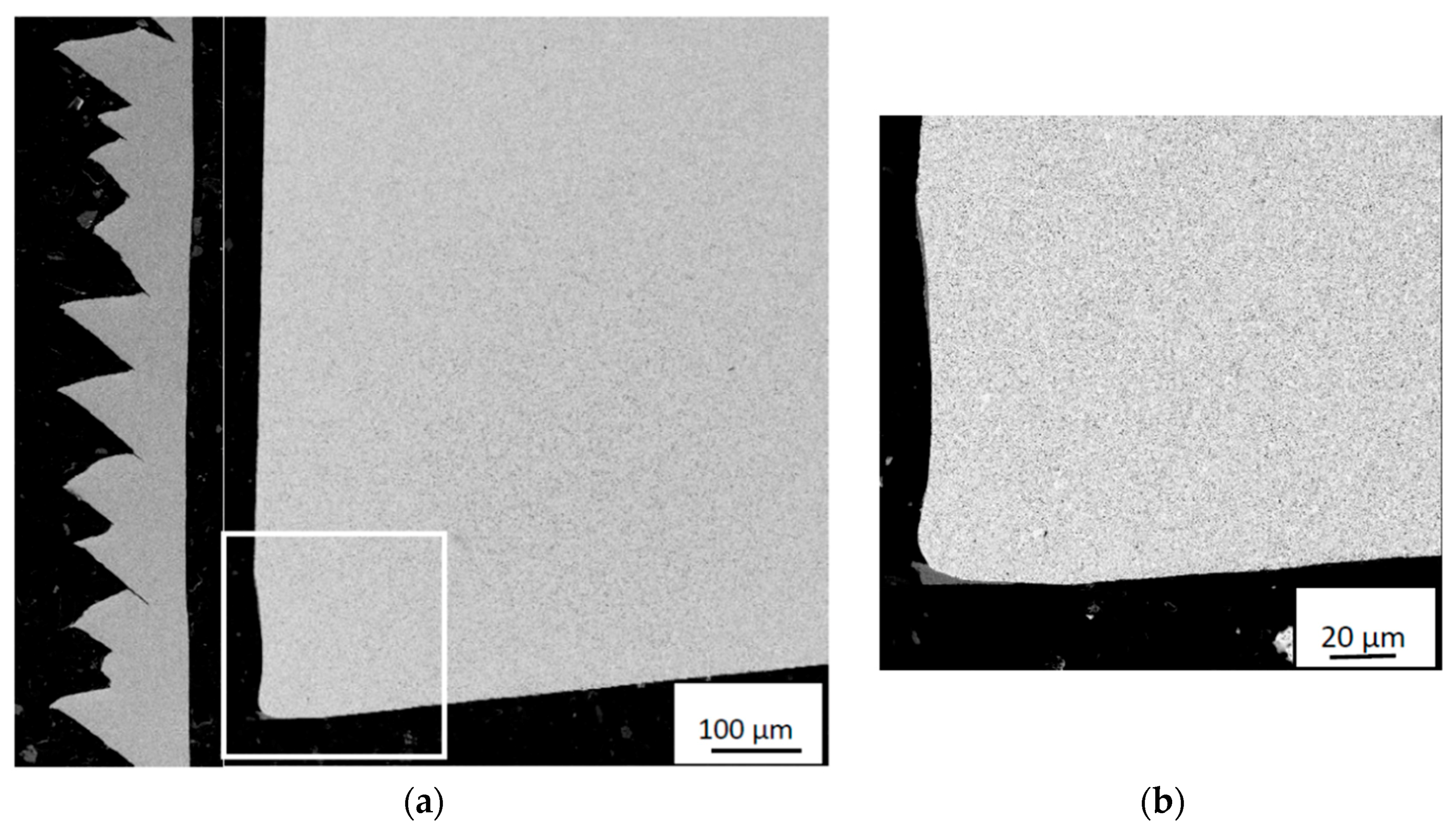
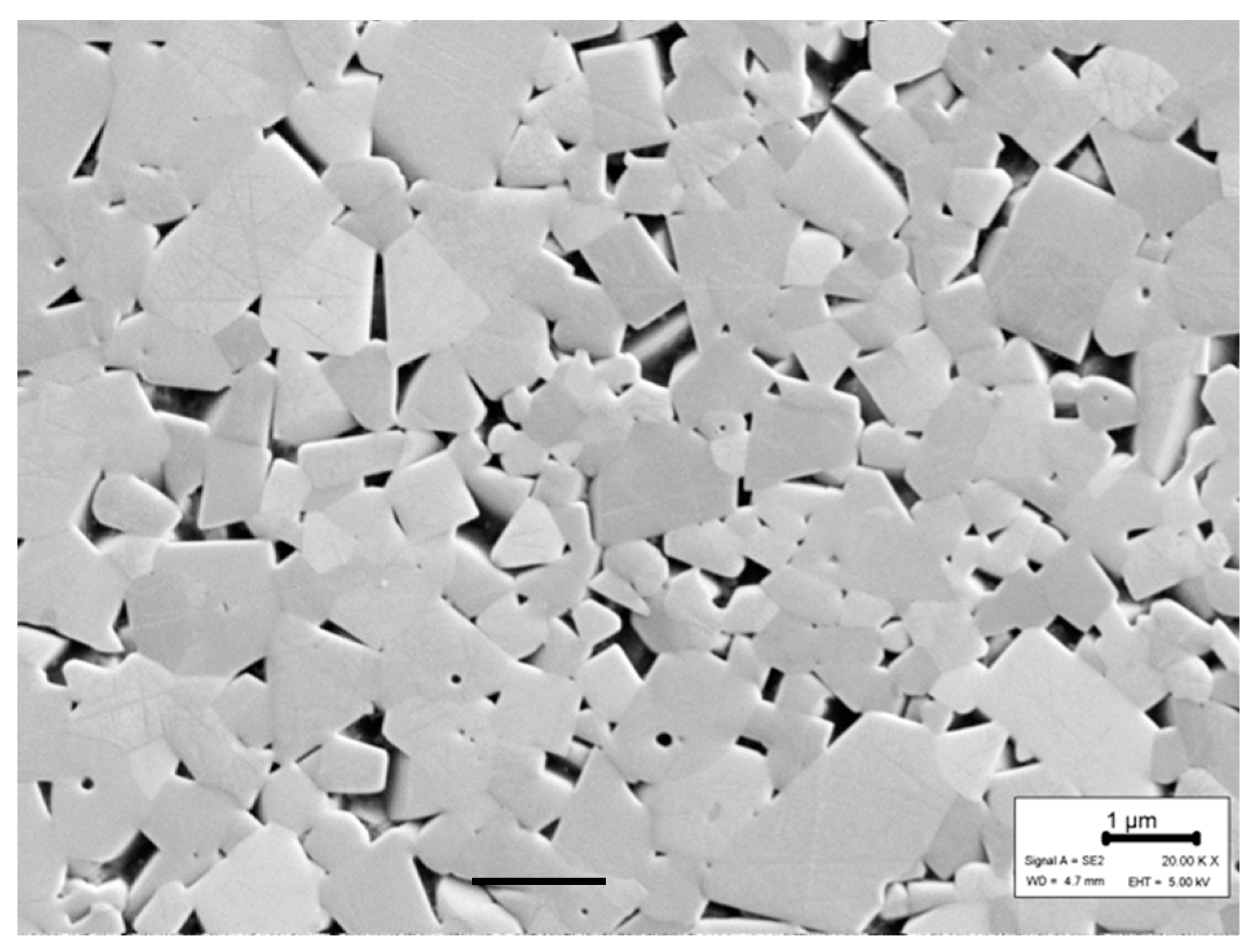
2.1. Materials
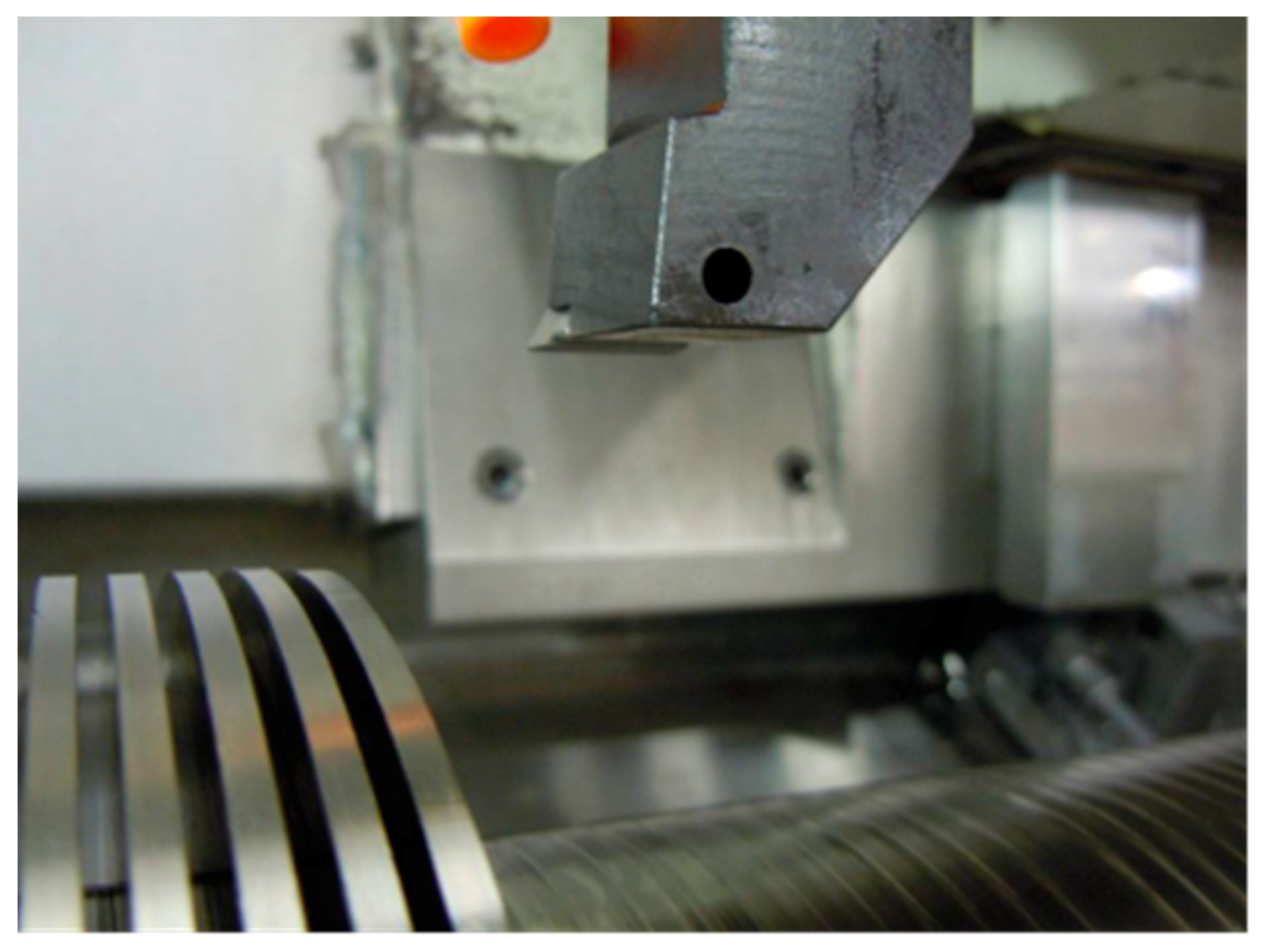
2.2. Turning Tests
2.3. Post Test Evaluation
2.3.1. Tool Wear
2.3.2. Wear Mechanisms
3. Results
3.1. Contact Conditions at the Cutting Insert/Work Material Interface
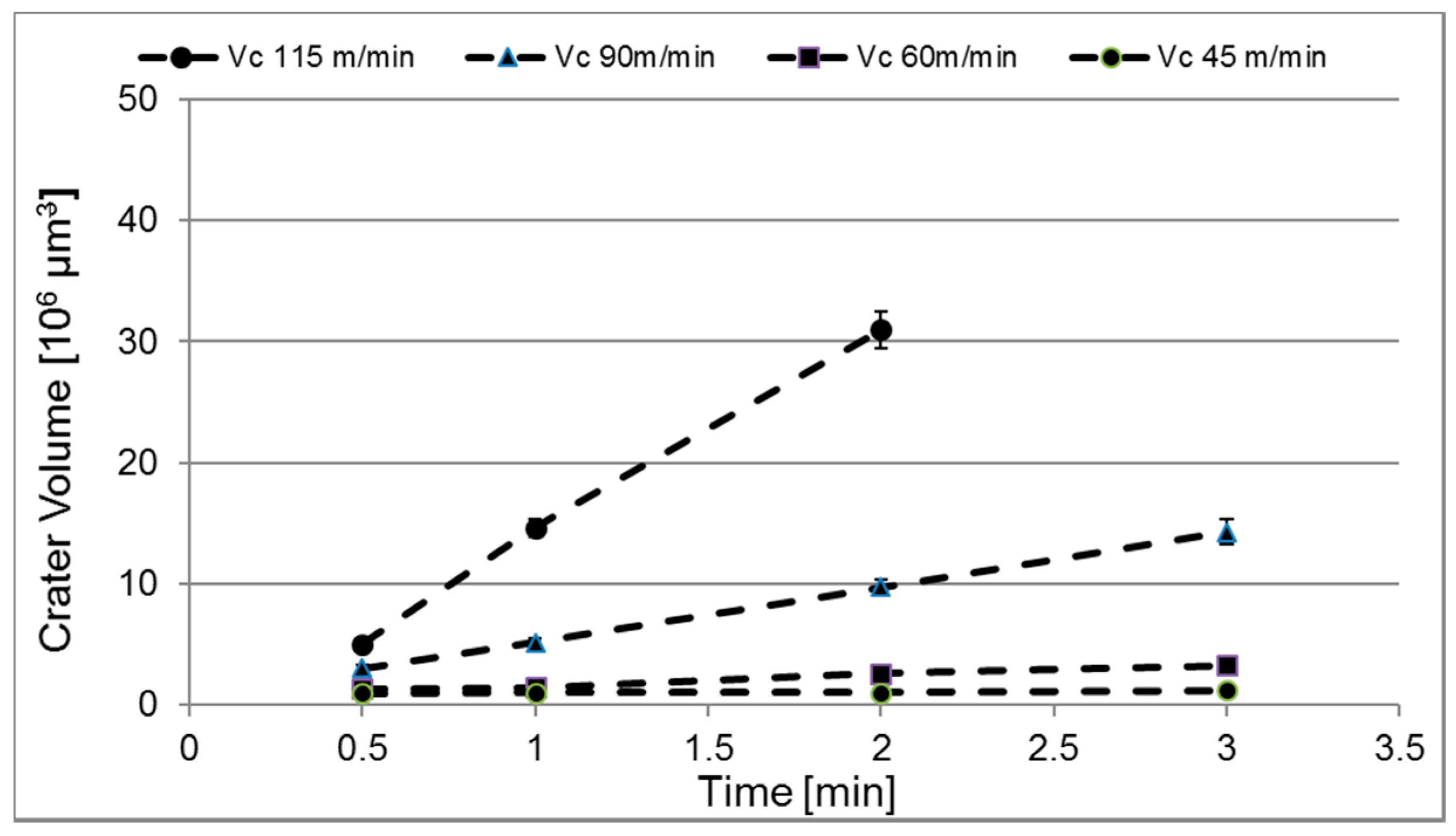
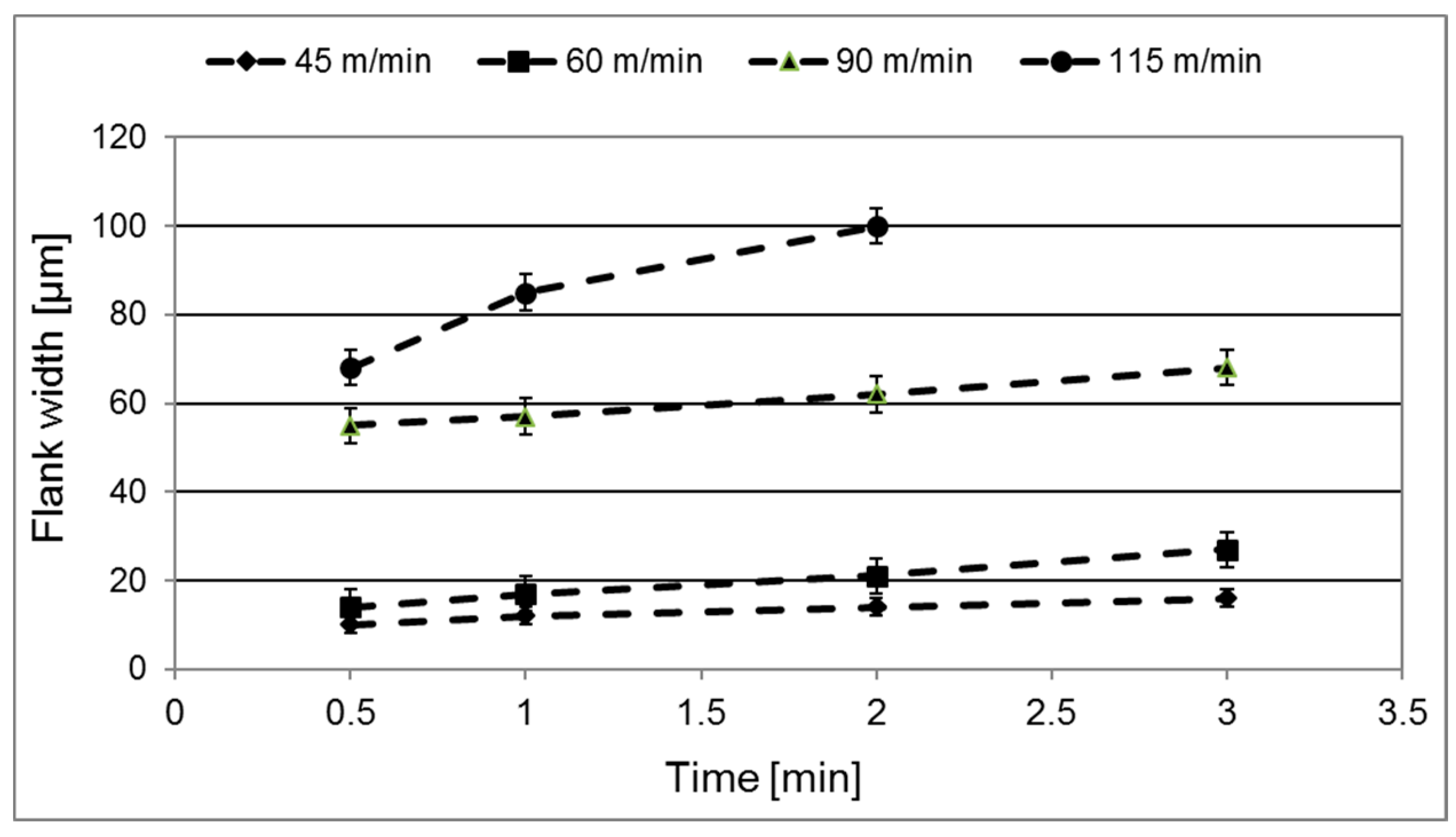
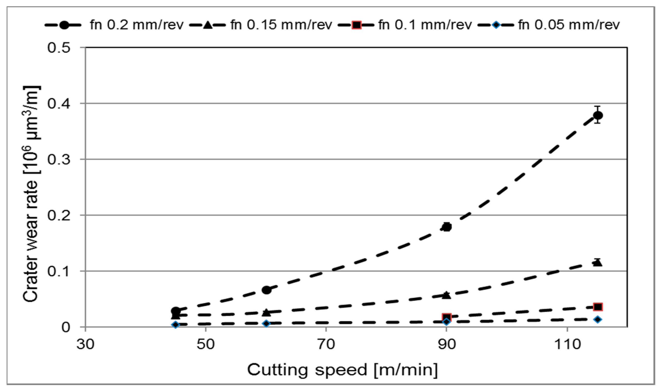
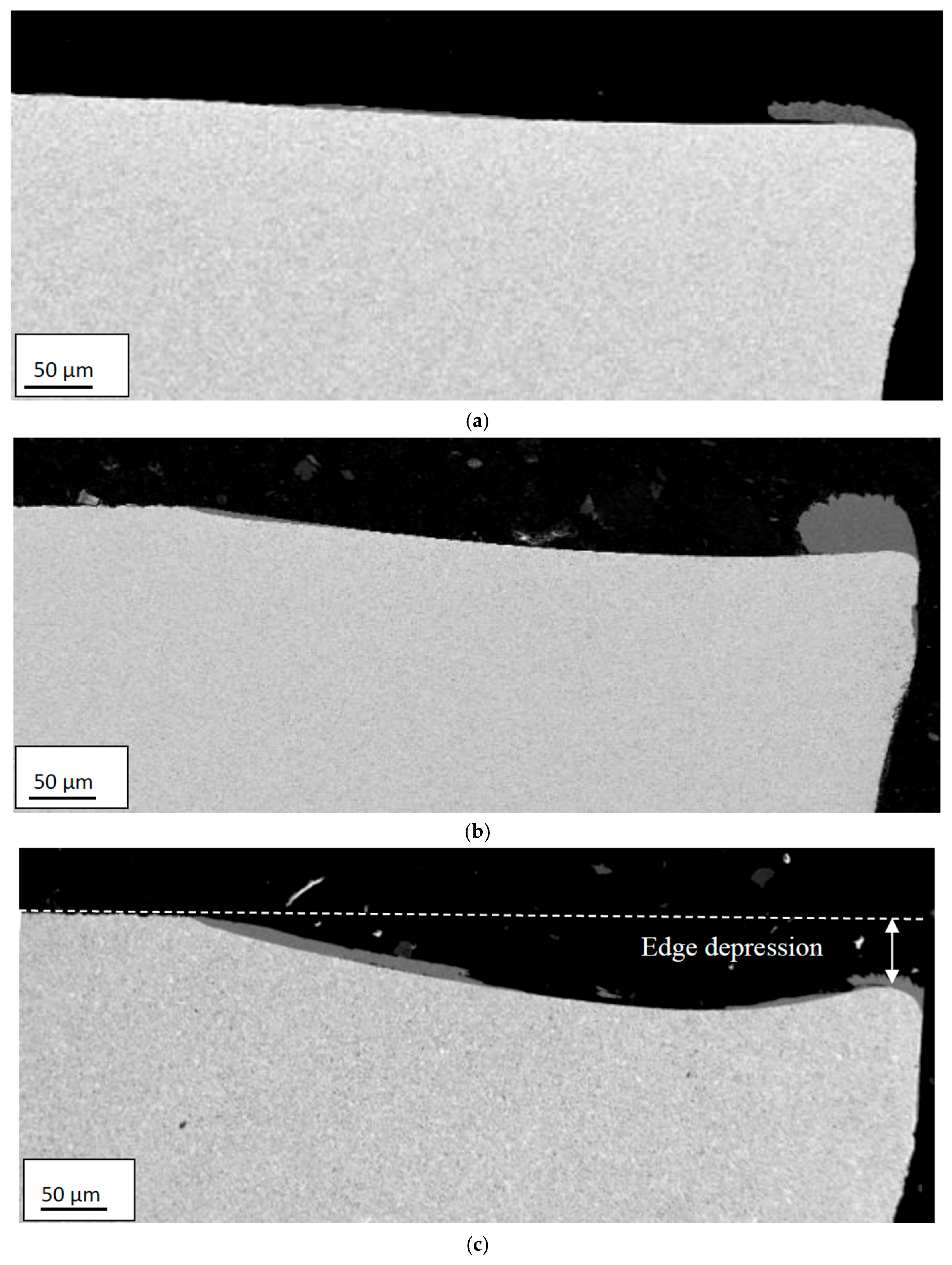
3.2. Wear Characteristics
3.3. Wear Mechanisms
4. Discussion
5. Conclusions
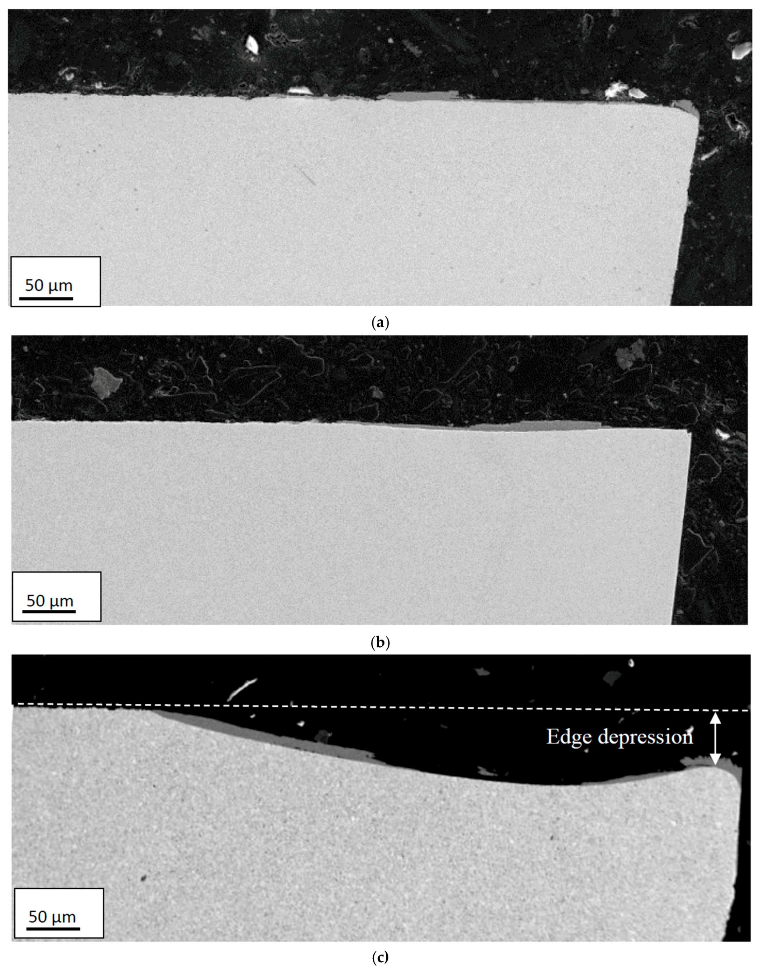
- Crater and flank wear of the cemented carbide inserts increase with increasing temperature at the cutting zone, i.e., with increasing cutting speed and feed.
- Crater and flank wear for combinations of low cutting speeds and feeds, are controlled by an attrition wear mechanism while diffusion wear mechanism was found to control the wear in the case of combination of media to high cutting speeds and feeds.
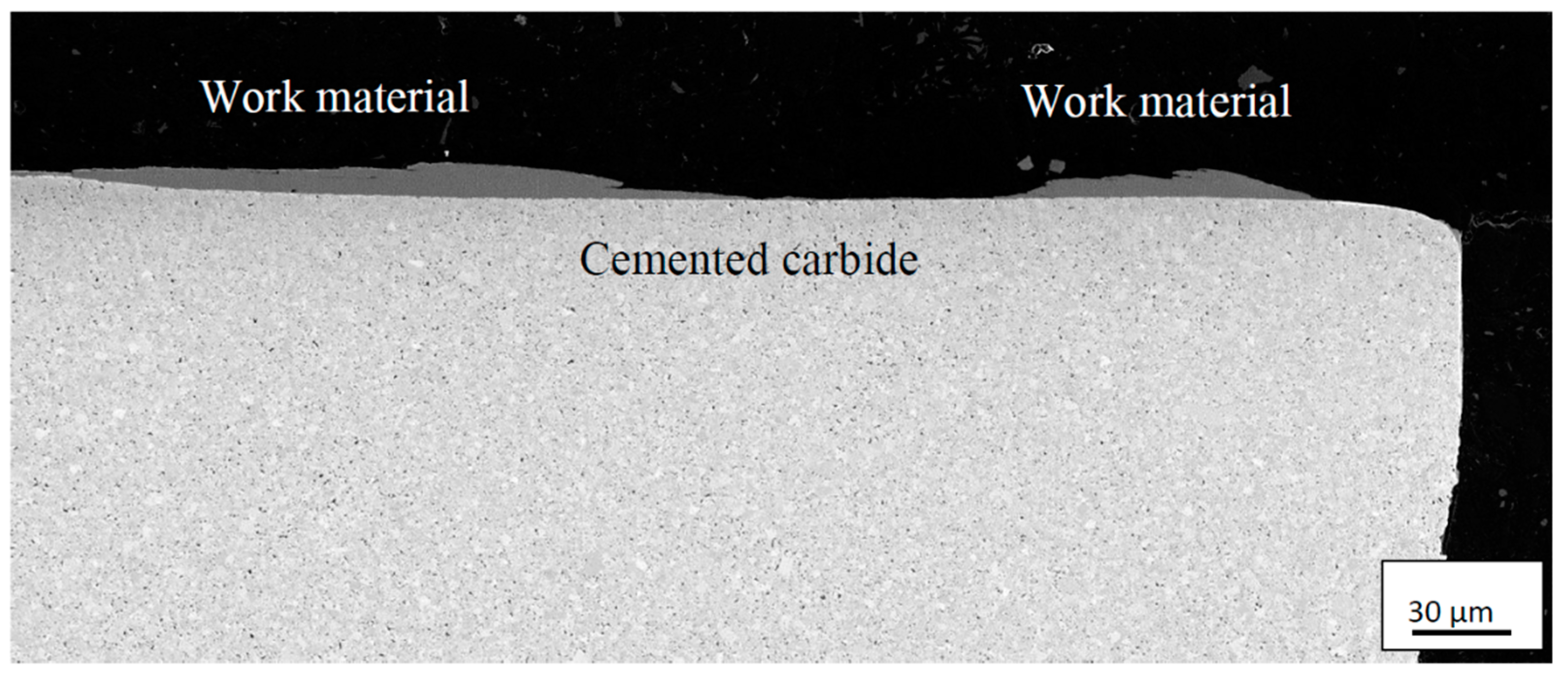
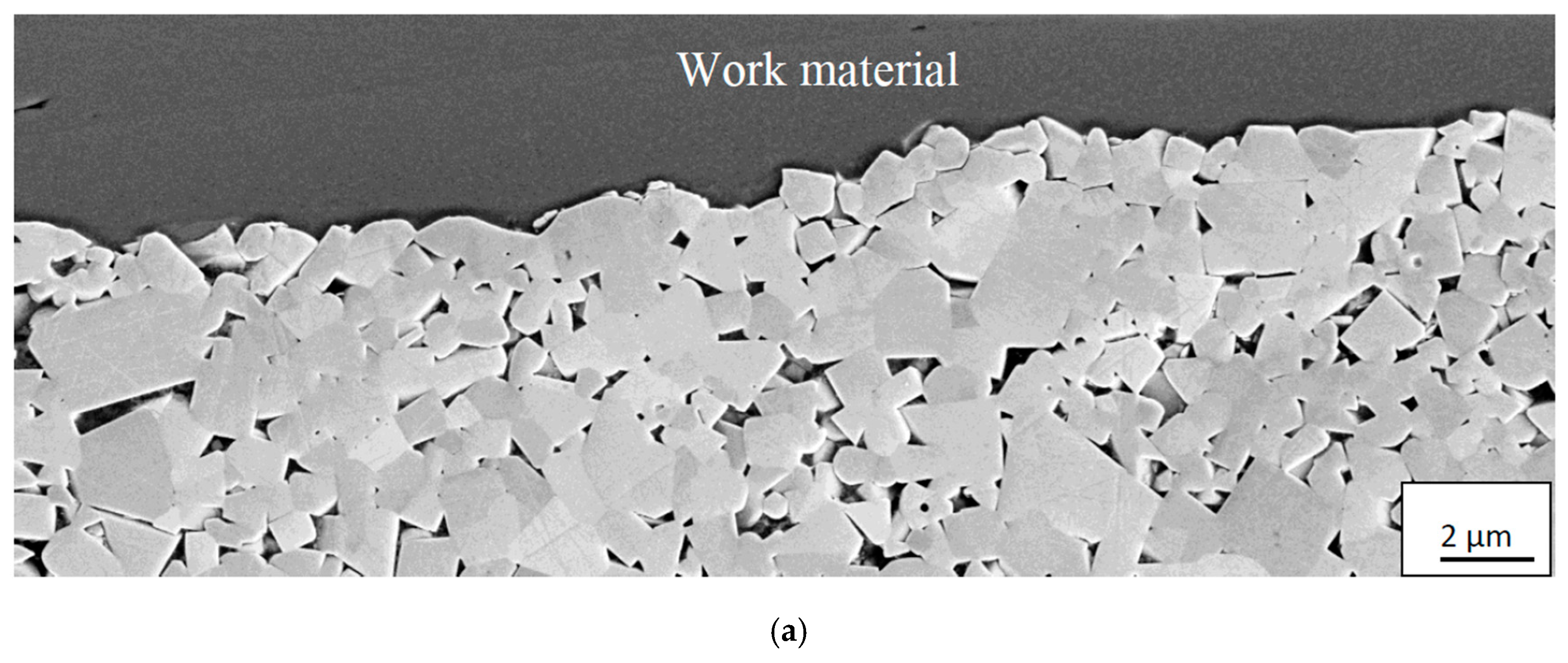
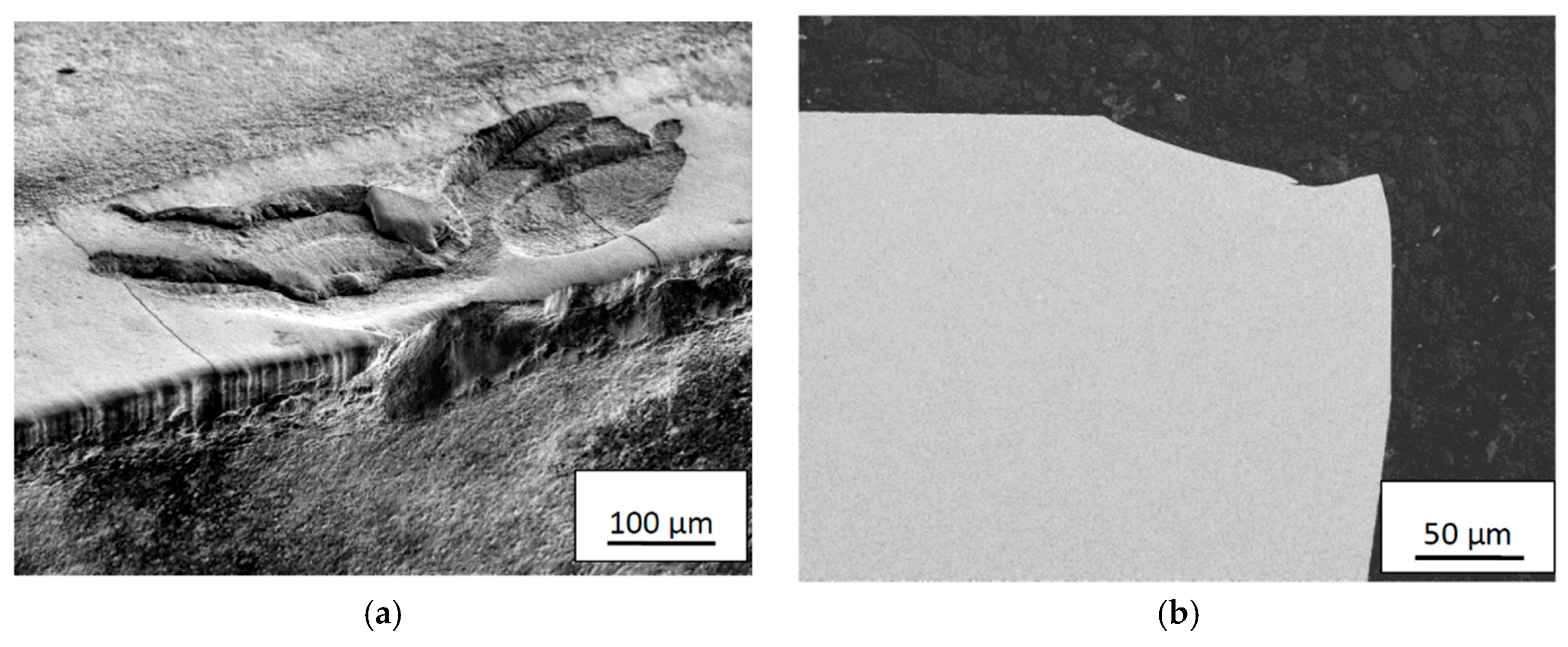
- At low cutting speeds or feeds, the worn cemented carbide displays a rough worn surface underneath the adhered work material indicating that fragments of WC grains or individual WC grains had been torn away when the adhered work material layer is removed by the chip.
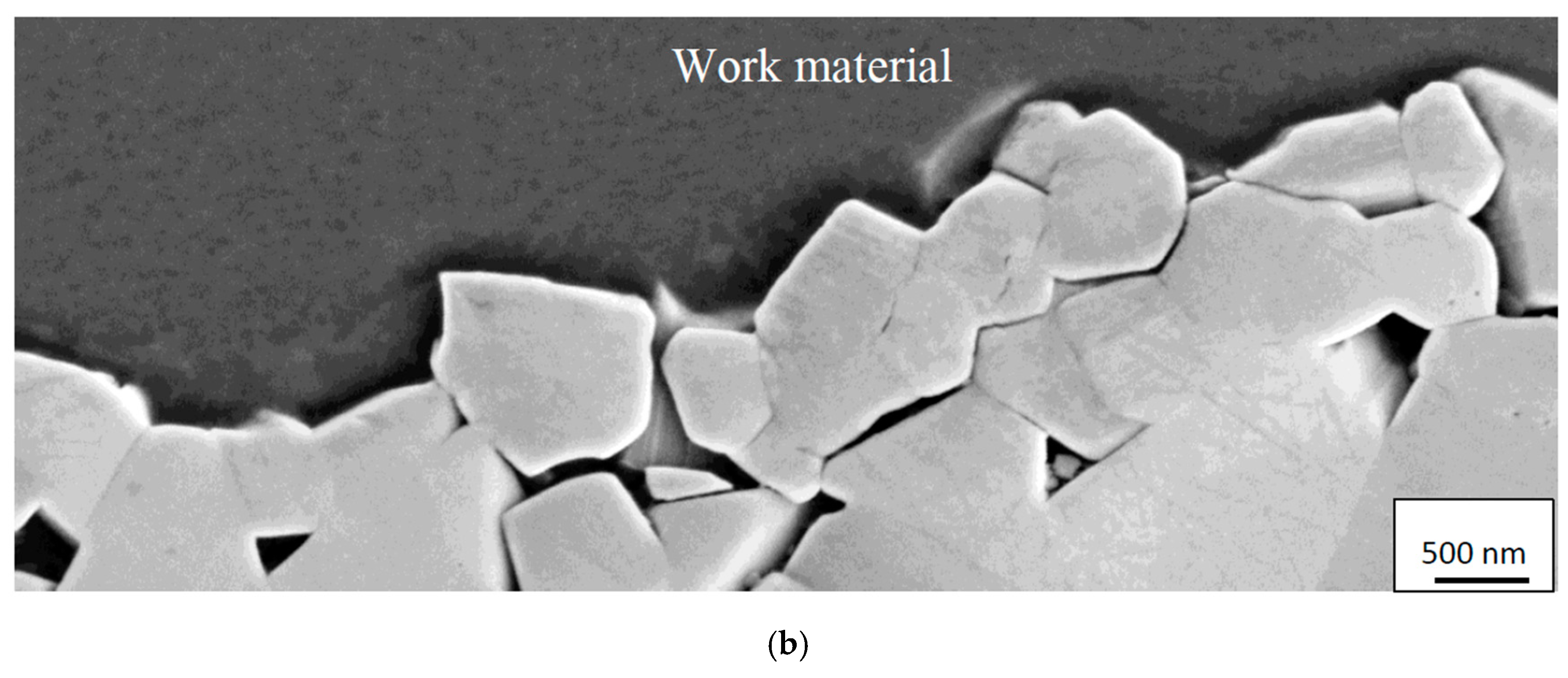
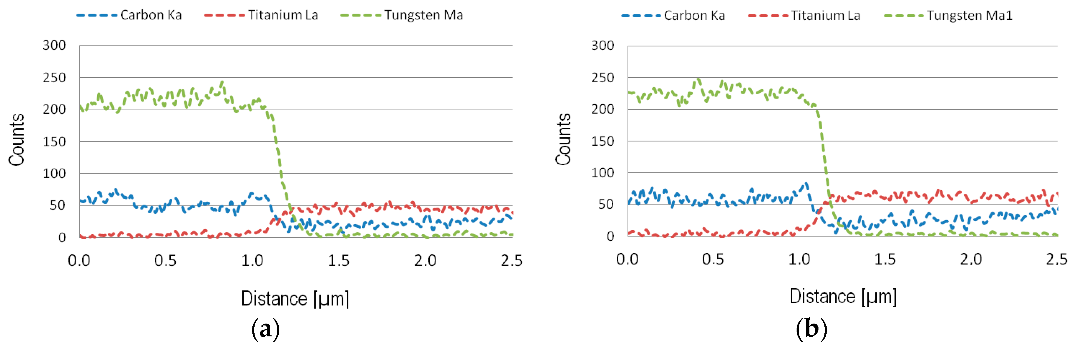
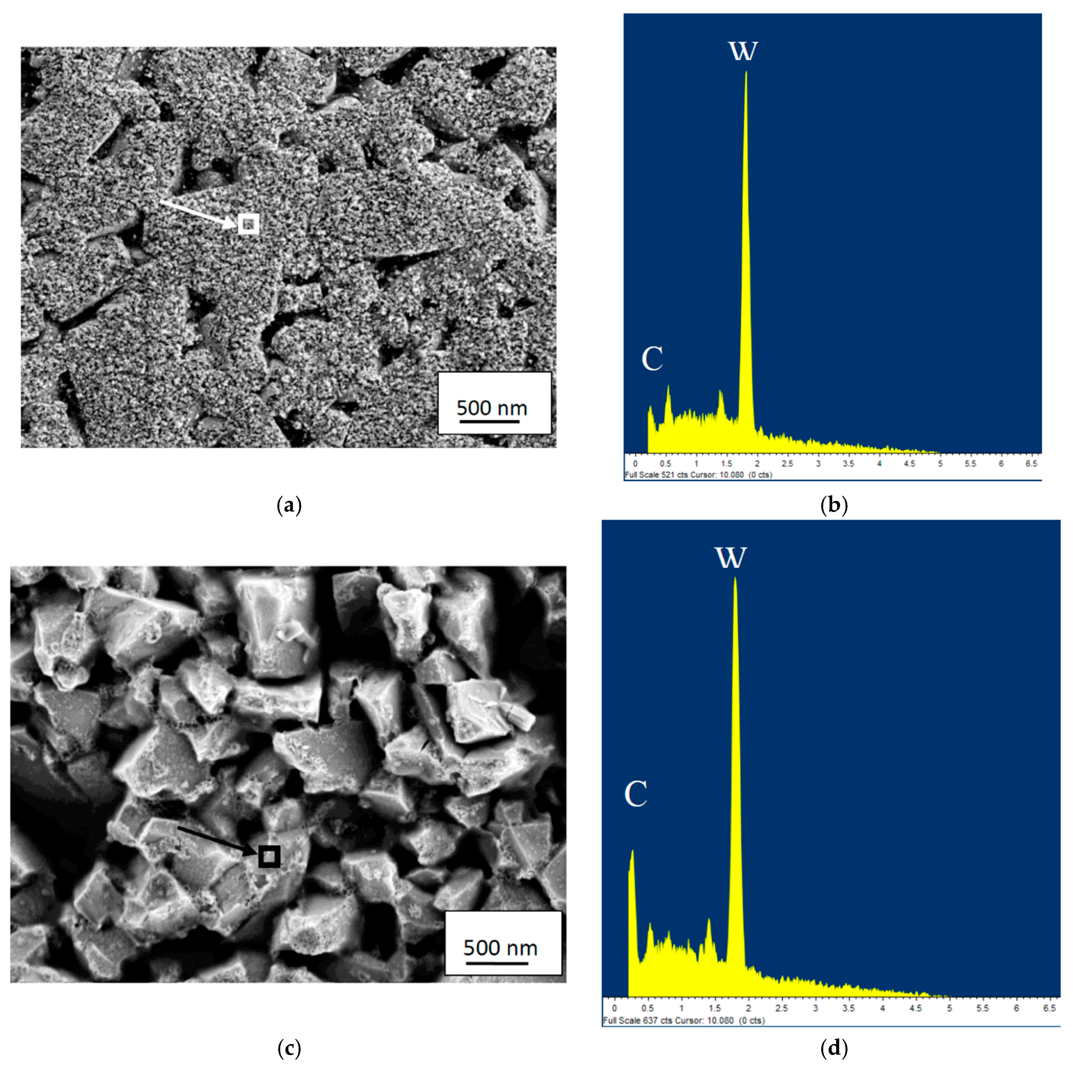
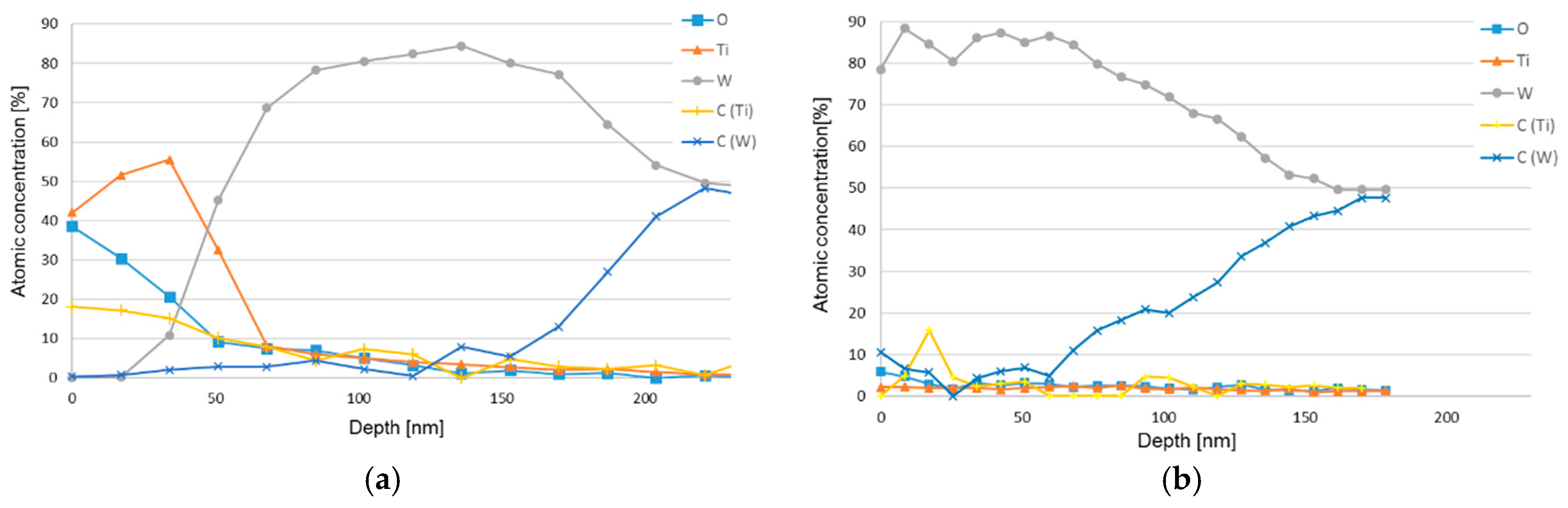
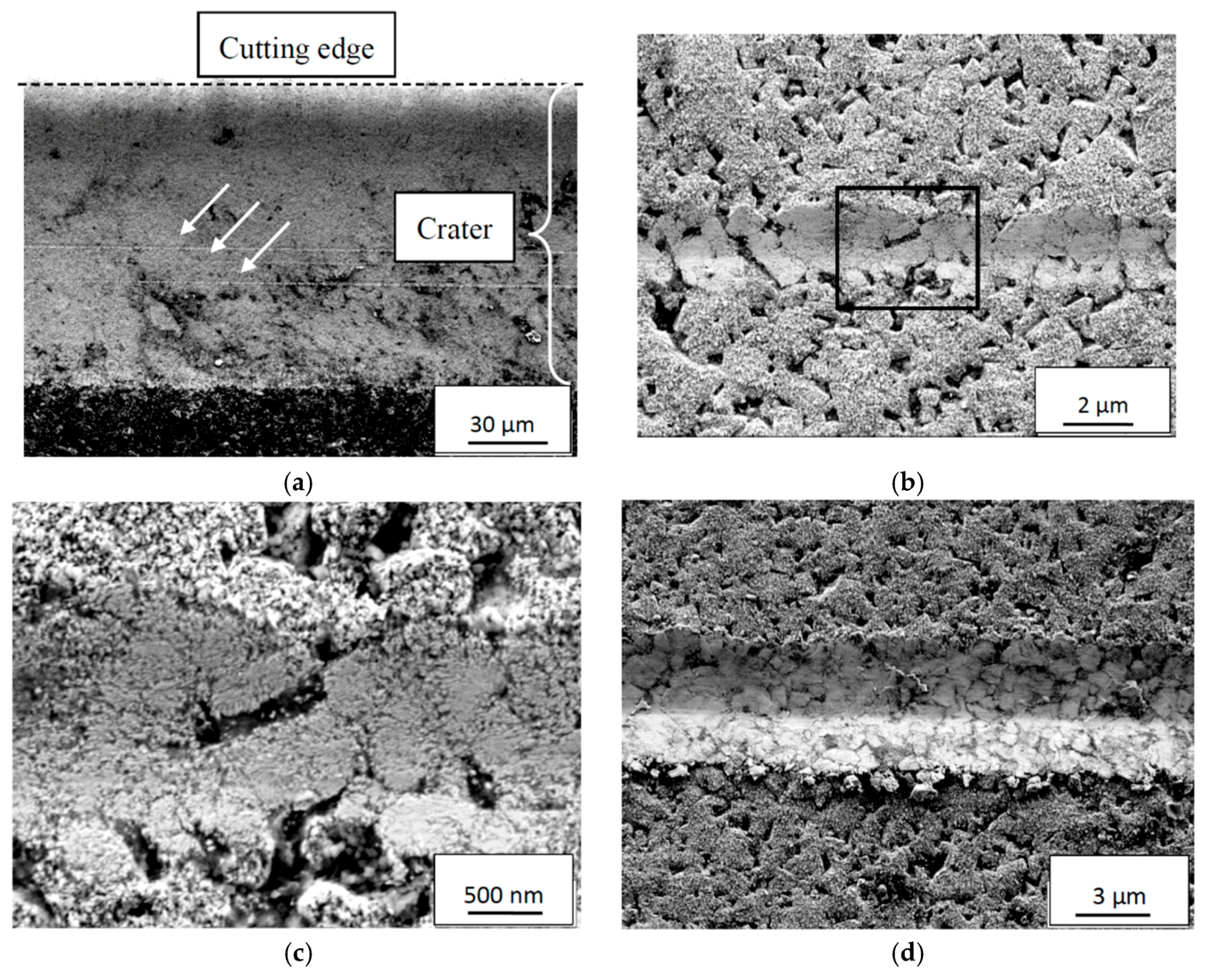
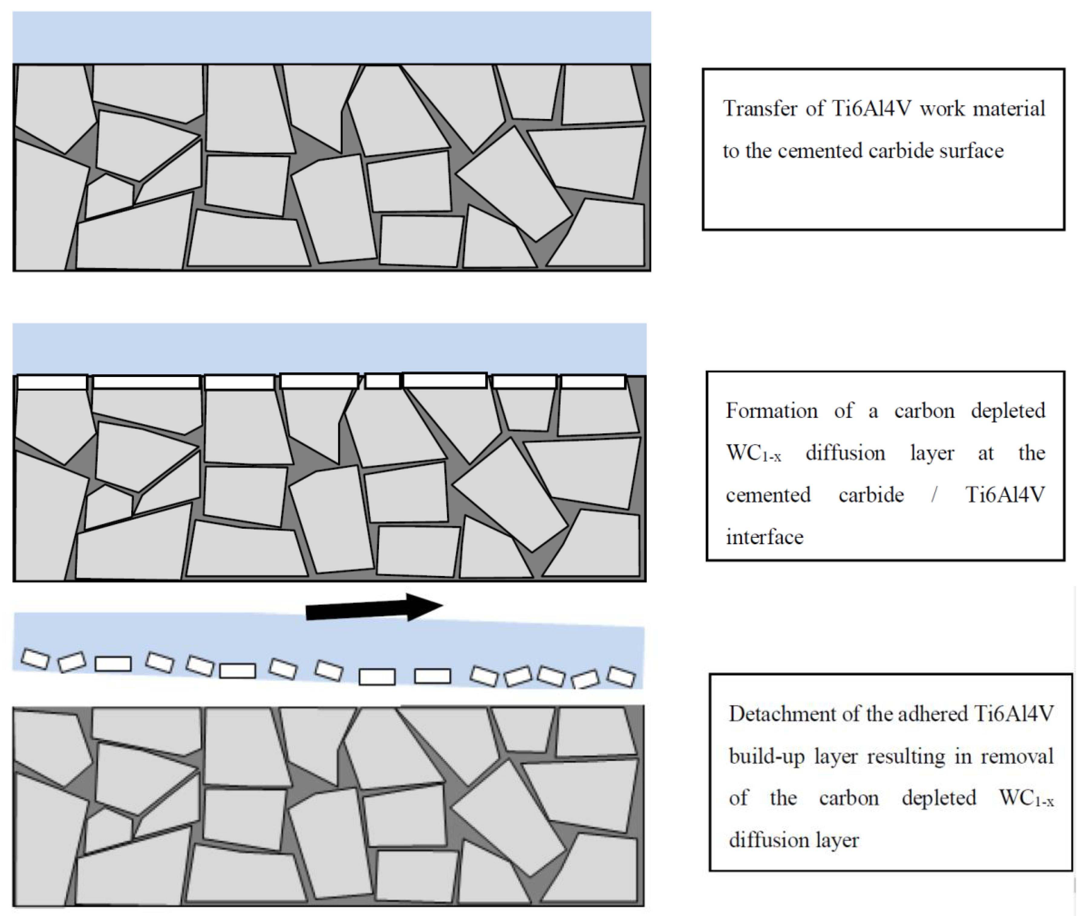
- At medium to high cutting speeds or feeds, the worn cemented carbide displays a very smooth worn surface underneath the adhered work material. High-resolution SEM, EDS and AES depth profile analysis reveal the formation of an approximately 100–150 nm thick carbon-depleted WC-layer at the cemented carbide/Ti6Al4V interface due to the diffusion of carbon into the adhered work material on the rake and flank surfaces.
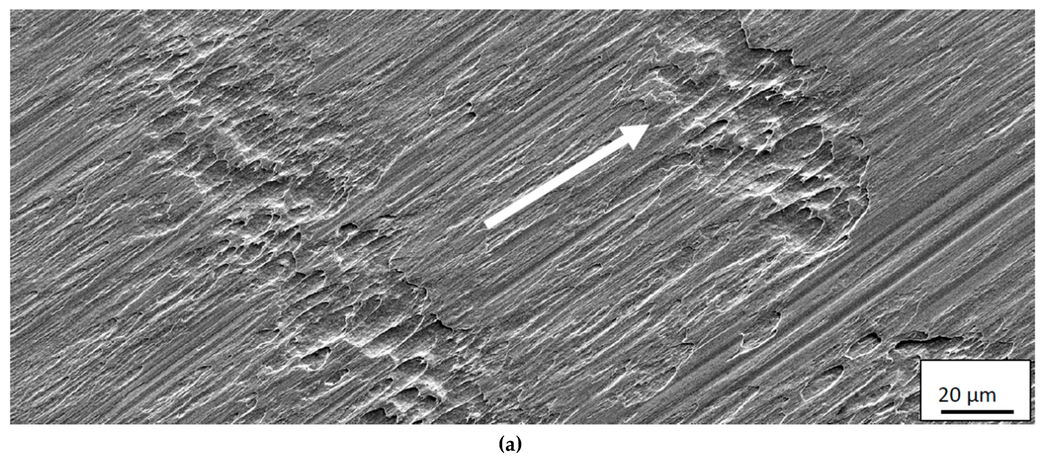
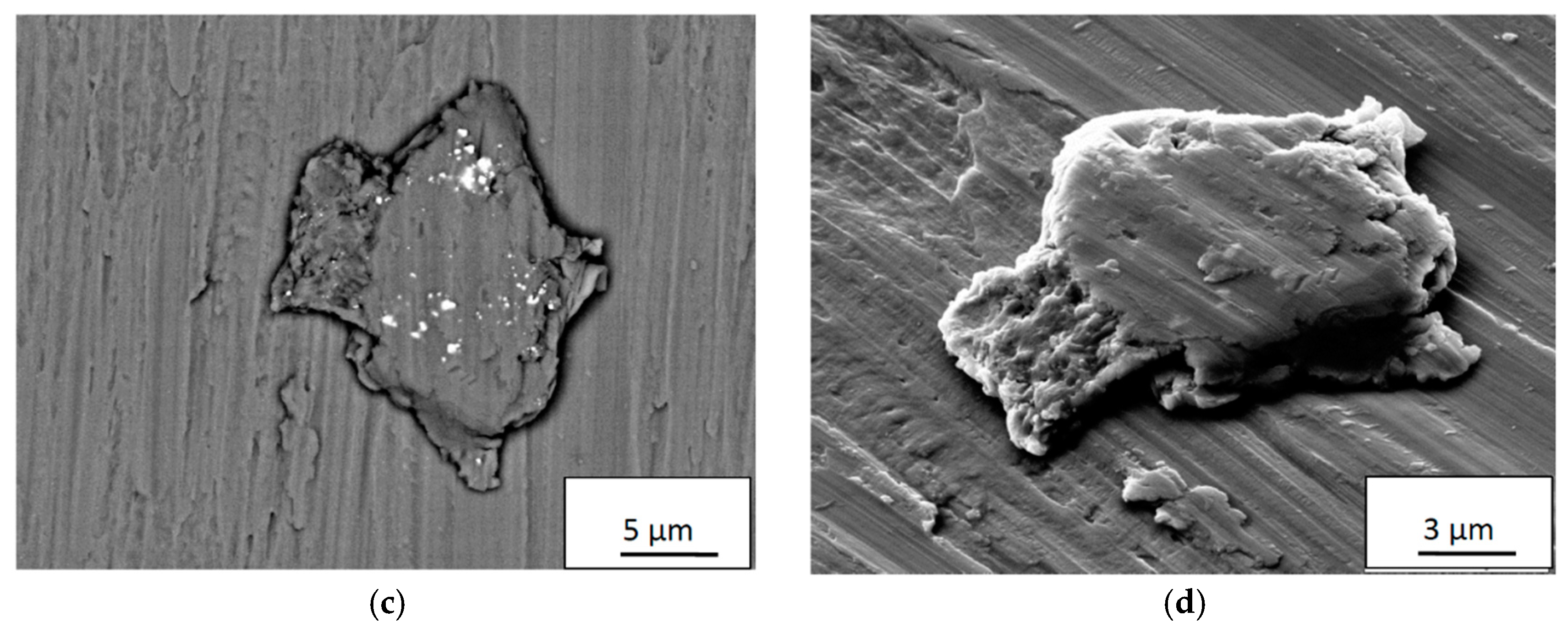
- Detailed SEM and EDS analysis of the back-side of the chips reveals the presence of Ti6Al4V build up layer fragments containing fine debris originating from the carbon-depleted WC-layer.
- Severe plastic deformation and macro cracking/fracture of the cutting edge region which may result in catastrophic failure is due to combinations of high cutting speed and feed.
Author Contributions
Funding
Acknowledgments
Conflicts of Interest
References
- Trent, E.M.; Wright, P.K. Metal Cutting, 4th ed.; Elsevier: New York, NY, USA, 2000; ISBN 0-7506-7069-X. [Google Scholar]
- Childs, T.H.C.; Maekawa, K.; Obikawa, T.; Yamane, Y. Metal Machining–Theory and Applications; Elsevier: New York, NY, USA, 2000; ISBN 0-340-69159-X. [Google Scholar]
- Archard, J.F. Contact and rubbing of flat surfaces. J. Appl. Phys. 1953, 24, 981–988. [Google Scholar] [CrossRef]
- Usui, E.; Shirakashi, T.; Kitagawa, T. Analytical prediction of cutting tool wear. Wear 1984, 100, 129–151. [Google Scholar] [CrossRef]
- Zanger, F.; Schulze, V. Investigations on mechanisms of tool wear in machining of Ti-6Al-4V using FEM simulation. Procedia CIRP 2013, 8, 158–163. [Google Scholar] [CrossRef]
- Kaplan, B.; Odelros, S.; Kritikos, M.; Bejjani, R.; Norgren, S. Study of tool wear and chemical interaction during machining of Ti6Al4V. Int. J. Refract. Met. Hard Mater. 2018, 72, 253–256. [Google Scholar] [CrossRef]
- Odelros, S.; Kaplan, B.; Kritikos, M.; Johansson, M.; Norgren, S. Experimental and theoretical study of the microscopic crater wear mechanism in titanium machining. Wear 2017, 376–377, 115–124. [Google Scholar] [CrossRef]
- Hatt, O.; Crawforth, P.; Jackson, M. On the mechanism of tool crater wear during titanium alloy machining. Wear 2017, 374–375, 15–20. [Google Scholar] [CrossRef]
- Edin, E.; Luo, W.; Ahuja, R.; Kaplan, B.; Blomqvist, A. First principles study of C diffusion in WC/W interfaces observed in WC/Co tools after Ti-alloy machining. Comput. Mater. Sci. 2019, 161, 236–243. [Google Scholar] [CrossRef]
- Olvera, D.; López de Lacalle, L.N.; Urbikain, G.; Lamikiz, A.; Rodal, P.; Zamakona, I. Hole Making Using Ball Helical Millin on Titanium Alloys. Mach. Sci. Technol. 2012, 16, 173–188. [Google Scholar] [CrossRef]
- Urbicain, G.; Olvera, D.; López de Lacalle, L.N.; Zamakona, I.; Rodal, P. New Strategies for Hole Making in Ti-6Al-4V. In Proceedings of the AIP Conference Proceedings, Alcoy, Spain, 17–19 June 2009. [Google Scholar]
- Arrazola, P.-J.; Garay, A.; Iriarte, L.-M.; Armendiaa, M.; Marya, S.; Le Maitre, F. Machinability of titanium alloys (Ti6Al4V and Ti555.3). J. Mater. Process. Technol. 2009, 209, 2223–2230. [Google Scholar] [CrossRef]
- Armendia, M.; Garay, A.; Iriarte, L.-M.; Arrazola, P.-J. Comparison between the machiabilities of Ti6Al4V and TIMETAL 54M using uncoated WC-Co tools. J. Mater. Process. Technol. 2010, 210, 197–203. [Google Scholar] [CrossRef]
- Ribeiro, M.V.; Moreira, M.R.V.; Ferreira, J.R. Optimization of titanium alloy (6Al-4V) machining. J. Mater. Process. Technol. 2003, 143–144, 458–463. [Google Scholar] [CrossRef]
- Ezugwu, E.O.; Bonney, J.; Yamane, Y. An overview of the machinability of aeroengine alloys. J. Mater. Process. Technol. 2003, 134, 233–253. [Google Scholar] [CrossRef]
- Pramanik, A. Problems and solutions in the machining of Ti-alloys. Int. J. Adv. Manuf. Technol. 2014, 70, 919–928. [Google Scholar] [CrossRef]
- Machado, A.R.; Wallbank, J. Machining of titanium and its alloys—A review. Proc. Inst. Mech. Eng. B J. Eng. 1990, 204, 53–60. [Google Scholar] [CrossRef]
- Davim, J.P. Machining of Titanium Alloys; Springer: Berlin, Germany, 2014; ISBN 978-3-662-43901-2. [Google Scholar]
- Su, Y.; He, N.; Li, L.; Li, X.L. An experimental investigation of effects of cooling/lubrication conditions on tool wear in high-speed end milling of Ti-6Al-4V. Wear 2006, 261, 760–766. [Google Scholar] [CrossRef]
- Ezugwu, E.O.; Wang, Z.M. Titanium alloys and their machinability: A review. J. Mater. Process. Technol. 1997, 68, 262–274. [Google Scholar] [CrossRef]
- Oliaei, S.N.B.; Karpat, Y. Investigating the influence of built-up edge on forces and surface roughness in micro scale orthogonal machining of titanium alloy Ti6Al4V. J. Mater. Process. Technol. 2016, 235, 28–40. [Google Scholar] [CrossRef]
- Kahles, J.F.; Field, M.; Eylon, D.; Froes, F.H. Machining of titanium alloys. J. Met. 1985, 37, 27–35. [Google Scholar] [CrossRef]
- Dearnly, P.A.; Grearson, A.N. Evaluation of principal wear mechanisms of cemented carbides and ceramics used for machining titanium alloy IMI 318. Mater. Sci. Technol. 1986, 2, 47–58. [Google Scholar] [CrossRef]
- Hartung, P.D.; Kamer, B.M. Tool wear in Titanium Machining. CIRP Ann. Manuf. Technol. 1982, 31, 75–80. [Google Scholar] [CrossRef]
- Deng, J.X.; Li, Y.S.; Song, W.L. Diffusion wear in dry cutting of Ti-6Al-4V with WC/Co carbide tools. Wear 2008, 265, 1776–1783. [Google Scholar]
- Nouari, M.; Makich, H. Experimental investigation on the effect of the material microstructure on tool wear when machining hard titanium alloys: Ti6Al-4V and Ti-555. Int. J. Refract. Met. Hard Mater. 2013, 41, 259–269. [Google Scholar] [CrossRef]
- Venugopal, K.A.; Paul, S.; Chattopadhyay, A.B. Growth of tool wear in turning of Ti-6Al-4V alloy under cryogenic cooling. Wear 2007, 262, 1071–1078. [Google Scholar] [CrossRef]
- Zhang, S.; Li, J.F.; Deng, J.X.; Li, Y.S. Investigation on diffusion wear during high speed machining Ti-6Al-4V alloy with straight tungsten carbide tools. Int. J. Adv. Manuf. Technol. 2009, 44, 17–25. [Google Scholar] [CrossRef]
- Jawaid, A.; Che-Haron, C.H.; Abdulla, A. Tool wear characteristics in turning of titanium alloy Ti-6246. J. Mater. Process. Technol. 1999, 92–93, 329–334. [Google Scholar] [CrossRef]
- Liang, L.; Li, X.-Q.; Li, Y.-Y. Wear mechanisms of WC-10NI3Al carbide tool in dry turning of Ti6Al4V. Int. J. Refract. Met. Hard Mater. 2015, 48, 272–285. [Google Scholar] [CrossRef]
- Che-Haron, C.H. Tool life and surface integrity in turning titanium alloy. Mater. Process. Technol. 2001, 118, 231–237. [Google Scholar] [CrossRef]
- Ezugwu, E.O.; Wang, Z.M.; Machado, A.R. Wear of coated carbide tools when machining nickel (Inconel 718) and titanium base (Ti-6Al-4V) alloys. Tribol. Trans. 2000, 43, 263–268. [Google Scholar] [CrossRef]
- Jawaid, A.; Sharif, S.; Koksal, S. Evaluation of wear mechanisms of coated carbide tools when face milling titanium alloy. J. Mater. Process. Technol. 2000, 99, 266–274. [Google Scholar] [CrossRef]
- Saketi, S.; Östby, J.; Bexell1, U.; Olsson, M. A Methodology to Systematically Investigate the Diffusion Degradation of Cemented Carbide during Machining of a Titanium Alloy. Materials 2019, 12, 2271. [Google Scholar] [CrossRef] [PubMed]
- Östberg, G.; Andrén, H.-O. Microstructural changes during wear by plastic deformation of cemented carbide and cermet cutting inserts. Metall. Mater. Trans. A 2006, 37, 1495–1506. [Google Scholar] [CrossRef]
- Östberg, G.; Buss, K.; Christensen, M.; Norgren, S.; Andrén, H.-O.; Mari, D.; Wahnström, G.; Reineck, I. Mechanisms of plastic deformation of WC-Co and Ti(C.,N)-WC-Co. Int. J. Refract. Met. Hard Mater. 2006, 24, 135–144. [Google Scholar] [CrossRef]
- Latteman, M.; Coronel, E.; Garcia, J.; Sadik, I. Interaction between cemented carbide and Ti6Al4V alloy in cryogenic machining. In Proceedings of the 19th Plansee Seminar, Reutte, Austria, 29 May–2 June 2017. [Google Scholar]
- Ramirez, C.; Idhil Ismail, A.; Gendarme, C.; Dehmas, M.; Aeby-Gautier, E.; Poulachon, G.; Rossi, F. Understanding the diffusion wear mechanisms of WC-10%Co carbide tools during dry machining of titanium alloys. Wear 2017, 390–391, 61–70. [Google Scholar] [CrossRef]


| WC [vol%] | Co [vol%] | WC Grain Size [µm] | Hardness, HV3 |
|---|---|---|---|
| 89.8 | 10.2 | 1 | 1580 |
| Al | V | Fe | C | O | N | Y | Ti | Hardness, HV5 |
|---|---|---|---|---|---|---|---|---|
| 6.425 | 3.970 | 0.155 | 0.019 | 0.190 | 0.006 | <0.001 | Bal. | 300 |
© 2019 by the authors. Licensee MDPI, Basel, Switzerland. This article is an open access article distributed under the terms and conditions of the Creative Commons Attribution (CC BY) license (http://creativecommons.org/licenses/by/4.0/).
Share and Cite
Saketi, S.; Odelros, S.; Östby, J.; Olsson, M. Experimental Study of Wear Mechanisms of Cemented Carbide in the Turning of Ti6Al4V. Materials 2019, 12, 2822. https://doi.org/10.3390/ma12172822
Saketi S, Odelros S, Östby J, Olsson M. Experimental Study of Wear Mechanisms of Cemented Carbide in the Turning of Ti6Al4V. Materials. 2019; 12(17):2822. https://doi.org/10.3390/ma12172822
Chicago/Turabian StyleSaketi, Sara, Stina Odelros, Jonas Östby, and Mikael Olsson. 2019. "Experimental Study of Wear Mechanisms of Cemented Carbide in the Turning of Ti6Al4V" Materials 12, no. 17: 2822. https://doi.org/10.3390/ma12172822
APA StyleSaketi, S., Odelros, S., Östby, J., & Olsson, M. (2019). Experimental Study of Wear Mechanisms of Cemented Carbide in the Turning of Ti6Al4V. Materials, 12(17), 2822. https://doi.org/10.3390/ma12172822