Effect of Deep Cryogenic Treatment on Microstructure and Wear Resistance of LC3530 Fe-Based Laser Cladding Coating


Abstract
1. Introduction
2. Materials and Methods
2.1. Materials
2.2. Laser Cladding and Deep Cryogenic Treatment
2.3. Microstructure Observation
2.4. Microhardness Test and Wear Test
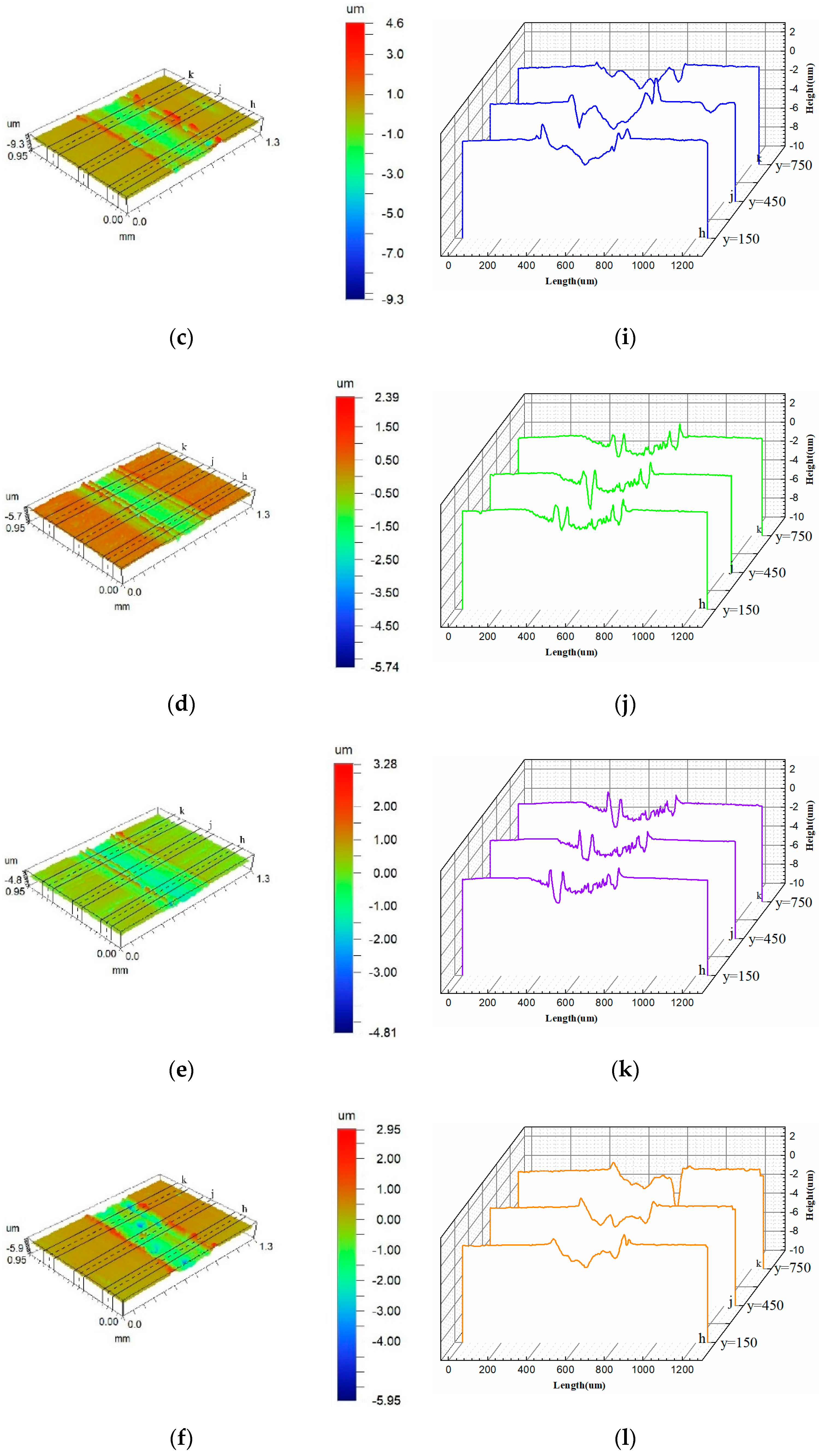
2.5. Wear Surface Profile and Wear Scar Morphology
3. Results and Discussion
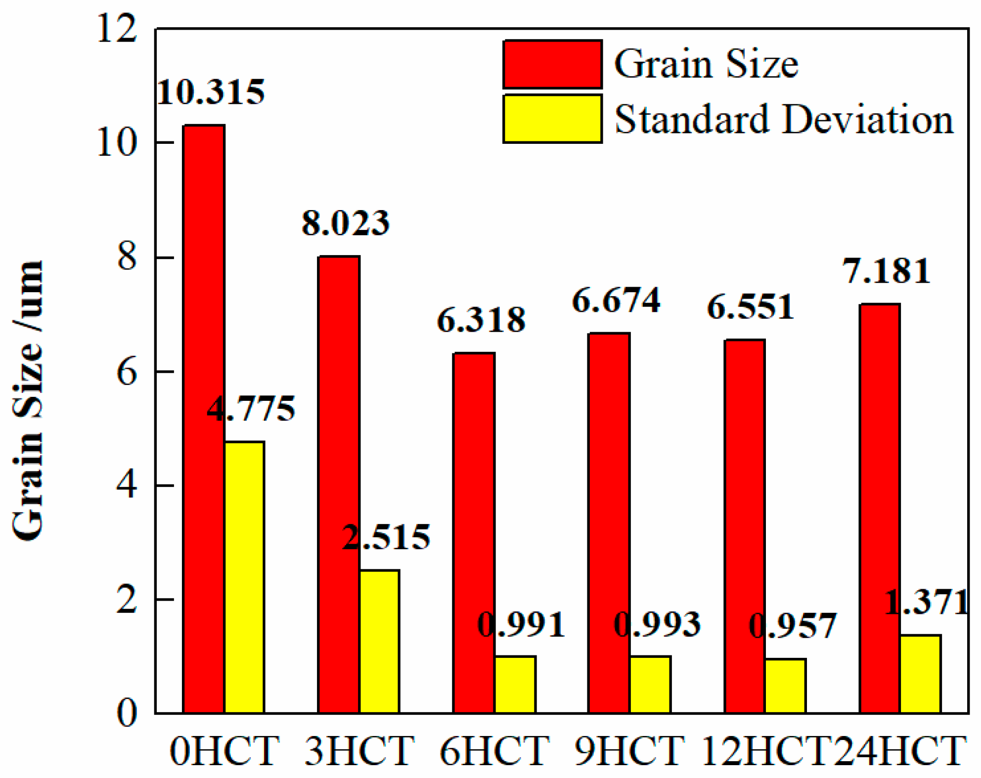
3.1. Microstructure
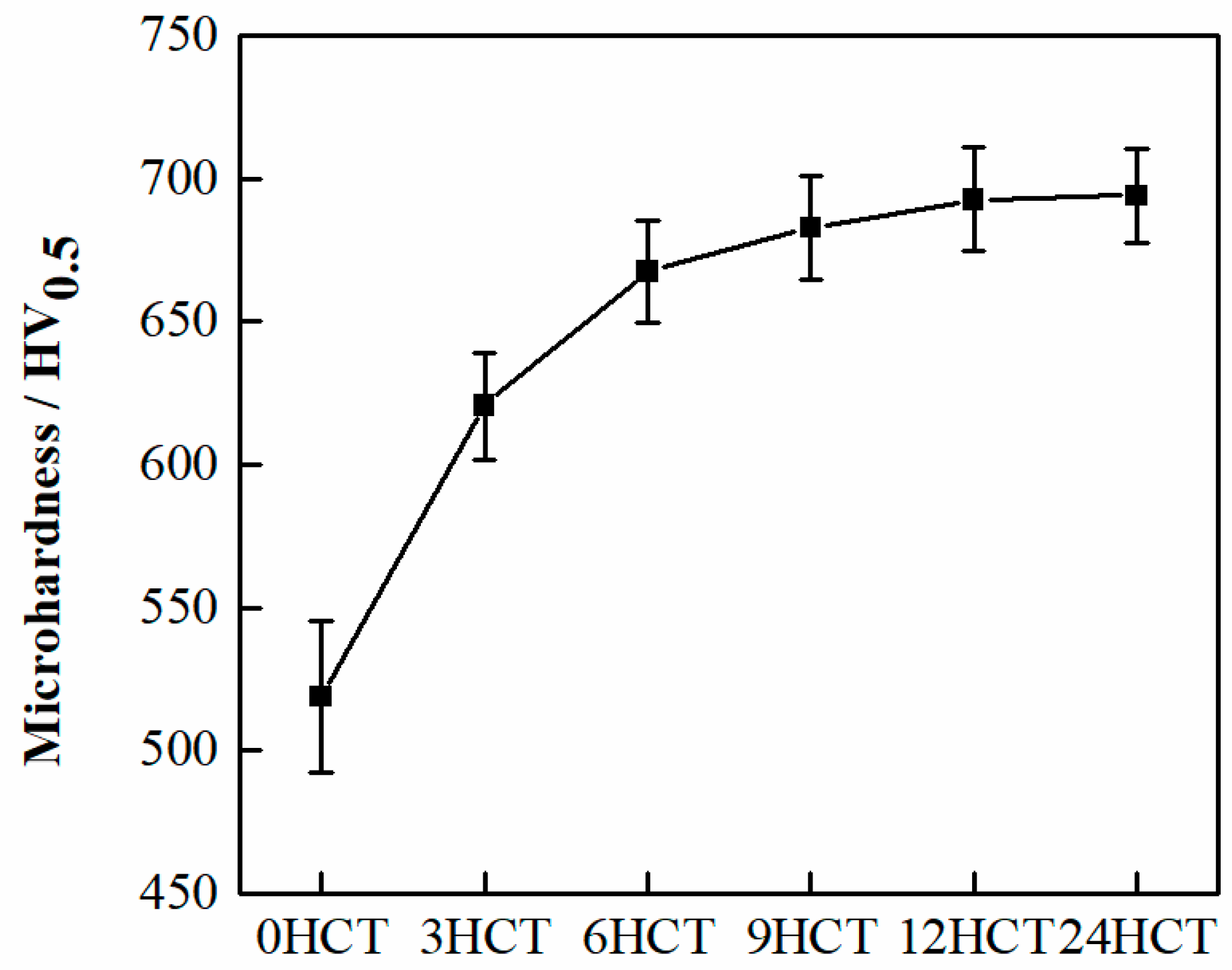
3.2. Microhardness
3.3. Coefficient of Friction
3.4. Worn Surface Morphology
3.5. Wear Factor
3.6. SEM Results of Wear Scars
4. Conclusions
Author Contributions
Funding
Acknowledgments
Conflicts of Interest
References
- Chen, J.; Guo, C.; Zhou, J. Microstructure and tribological properties of laser cladding Fe-based coating on pure Ti substrate. Trans. Nonferrous Met. Soc. Chin. 2012, 22, 2171–2178. [Google Scholar] [CrossRef]
- Martínez, S.; Lamikiz, A.; Ukar, E.; Calleja, A.; Arrizubieta, J.; De Lacalle, L.L. Analysis of the regimes in the scanner-based laser hardening process. Opt. Lasers Eng. 2017, 90, 72–80. [Google Scholar] [CrossRef]
- Fu, Z.; Ding, H.; Wang, W.; Liu, Q.; Guo, J.; Zhu, M. Investigation on microstructure and wear characteristic of laser cladding Fe-based alloy on wheel/rail materials. Wear 2015, 330, 592–599. [Google Scholar] [CrossRef]
- Yakovlev, A.; Bertrand, P.; Smurov, I. Laser cladding of wear resistant metal matrix composite coatings. Thin Solid Films 2004, 453, 133–138. [Google Scholar] [CrossRef]
- Yao, Y.; Zhou, Y. Effects of deep cryogenic treatment on wear resistance and structure of GB 35CrMoV steel. Metals 2018, 8, 502. [Google Scholar] [CrossRef]
- Ramos, L.B.; Simoni, L.; Mielczarski, R.G.; Vega, M.R.O.; Schroeder, R.M.; Malfatti, C.D.F. Tribocorrosion and electrochemical behavior of DIN 1.4110 martensitic stainless steels after cryogenic heat treatment. Mater. Res. 2017, 20, 460–468. [Google Scholar] [CrossRef]
- Sehri, M.; Ghayour, H.; Amini, K.; Naseri, M.; Rastegari, H.; Javaeri, V. Effects of cryogenic treatment on microstructure and wear resistance of Fe-0.35C-6.3Cr martensitic steel. Acta Met. Slovaca 2018, 24, 134–146. [Google Scholar] [CrossRef]
- Steier, V.F.; Badibanga, R.K.; Da Silva, C.R.M.; Nogueira, M.M.; Araújo, J.A. Effect of chromium nitride coatings and cryogenic treatments on wear and fretting fatigue resistance of aluminum. Electr. Power Syst. Res. 2014, 116, 322–329. [Google Scholar] [CrossRef]
- He, H.-B.; Han, W.-Q.; Li, H.-Y.; Li, D.-Y.; Yang, J.; Gu, T.; Deng, T. Effect of deep cryogenic treatment on machinability and wear mechanism of TiAlN coated tools during dry turning. Int. J. Precis. Eng. Manuf. 2014, 15, 655–660. [Google Scholar] [CrossRef]
- Kara, F.; Kıvak, T.; Ekici, E.; Çiçek, A.; Uygur, I. Effects of deep cryogenic treatment on the wear resistance and mechanical properties of AISI H13 hot-work tool steel. J. Mater. Eng. Perform. 2015, 24, 4431–4439. [Google Scholar]
- Bai, X.; Zheng, L.; Cui, J.; Wu, S.; Song, R.; Xie, D.; Wang, D.; Li, H. Effect of cryogenic treatment on microstructure and mechanical properties of 0Cr12Mn5Ni4Mo3Al steel. J. Mater. Eng. Perform. 2017, 26, 5079–5084. [Google Scholar] [CrossRef]
- Li, J.; Cai, X.; Wang, Y.; Wu, X. Multiscale analysis of the microstructure and stress evolution in cold work die steel during deep cryogenic treatment. Materials 2018, 11, 2122. [Google Scholar] [CrossRef] [PubMed]
- Vasylyev, M.; Mordyuk, B.; Sidorenko, S.; Voloshko, S.; Burmak, A. Influence of microstructural features and deformation-induced martensite on hardening of stainless steel by cryogenic ultrasonic impact treatment. Surf. Coat. Technol. 2018, 343, 57–68. [Google Scholar] [CrossRef]
- Darling, K.; Tschopp, M.; Roberts, A.; Ligda, J.; Kecskes, L.; Kecskes, L. Enhancing grain refinement in polycrystalline materials using surface mechanical attrition treatment at cryogenic temperatures. Scr. Mater. 2013, 69, 461–464. [Google Scholar] [CrossRef]
- Sola, R.; Giovanardi, R.; Parigi, G.; Veronesi, P. A novel methods for fracture toughness evaluation of tool steels with post-tempering cryogenic treatment. Metals 2017, 7, 75. [Google Scholar] [CrossRef]
- Damdhar, V.S.; Pande, K.N.; Peshwe, D.R.; Gogte, C.L. To investigate the wear mechanism on cryogenic treatment of PTFE-Mica filled composite coatings in cookware. Trans. Indian Inst. Met. 2015, 68, 611–621. [Google Scholar] [CrossRef]
- Çakir, F.H.; Çelik, O.N. The effects of cryogenic treatment on the toughness and tribological behaviors of eutectoid steel. J. Mech. Sci. Technol. 2017, 31, 3233–3239. [Google Scholar] [CrossRef]
- Ehtemam-Haghighi, S.; Prashanth, K.; Attar, H.; Chaubey, A.; Cao, G.; Zhang, L.; Gokuldoss, P.K. Evaluation of mechanical and wear properties of Ti xNb 7Fe alloys designed for biomedical applications. Mater. Des. 2016, 111, 592–599. [Google Scholar] [CrossRef]
- Attar, H.; Bermingham, M.; Ehtemam-Haghighi, S.; Dehghan-Manshadi, A.; Kent, D.; Dargusch, M. Evaluation of the mechanical and wear properties of titanium produced by three different additive manufacturing methods for biomedical application. Mater. Sci. Eng. A 2019, 760, 339–345. [Google Scholar] [CrossRef]
- Ehtemam-Haghighi, S.; Attar, H.; Dargusch, M.S.; Kent, D. Microstructure, phase composition and mechanical properties of new, low cost Ti-Mn-Nb alloys for biomedical applications. J. Alloy. Compd. 2019, 787, 570–577. [Google Scholar] [CrossRef]
- Zare, A.; Mansouri, H.; Hosseini, S.R. Influence of the holding time of the deep cryogenic treatment on the strain hardening behavior of HY-TUF steel. Int. J. Mech. Mater. Eng. 2015, 10, 24. [Google Scholar] [CrossRef]
- Pottirayil, A.; Kailas, S.V. Wear behavior of friction stir processed NAB alloys in marine environment. Tribol. Online 2018, 13, 75–80. [Google Scholar]
- Yao, J.; Ding, Y.; Liu, R.; Zhang, Q.; Wang, L. Wear and corrosion performance of laser-clad low-carbon high-molybdenum stellite alloys. Opt. Laser Technol. 2018, 107, 32–45. [Google Scholar] [CrossRef]
- Liu, Y.; Pang, S.; Yang, W.; Hua, N.; Liaw, P.K.; Zhang, T. Tribological behaviors of a Ni-free Ti-based bulk metallic glass in air and a simulated physiological environment. J. Alloy. Compd. 2018, 766, 1030–1036. [Google Scholar] [CrossRef]
- Cui, G.; Bi, Q.; Zhu, S.; Yang, J.; Liu, W. Tribological behavior of Cu–6Sn–6Zn–3Pb under sea water, distilled water and dry-sliding conditions. Tribol. Int. 2012, 55, 126–134. [Google Scholar] [CrossRef]
- Ratia, V.; Zhang, D.; Carrington, M.; Daure, J.; McCartney, D.; Shipway, P.; Stewart, D. The effect of temperature on sliding wear of self-mated HIPed Stellite 6 in a simulated PWR water environment. Wear 2019, 420–421, 215–225. [Google Scholar] [CrossRef]
- Cen, S.; Lv, X.; Xu, B.; Xu, Y. The effect of gradient bias design on electrochemistry and tribology behaviors of pvd crn film in a simulative marine environment. Materials 2018, 11, 1753. [Google Scholar] [CrossRef] [PubMed]
- Li, Z.; Zhou, Y.; Wang, S. Influence of strain and stress triaxiality on the fracture behavior of GB 35CrMo steel during hot tensile testing. Adv. Mater. Sci. Eng. 2018, 2018, 1–11. [Google Scholar] [CrossRef]
- Šolić, S.; Cajner, F.; Panjan, P. Influence of deep cryogenic treatment of high speed steel substrate on TiAlN coating properties. Materialwissenschaft Werkstofftechnik 2013, 44, 950–958. [Google Scholar] [CrossRef]
- Prieto, G.; Tuckart, W.R. Influence of cryogenic treatments on the wear behavior of AISI 420 martensitic stainless steel. J. Mater. Eng. Perform. 2017, 26, 5262–5271. [Google Scholar] [CrossRef]
- Yan, L. Investigation on indentation rolling resistance of belt conveyor based on Hertz contact theory compared with one-dimensional Winkler foundation. Adv. Mech. Eng. 2018, 10. [Google Scholar] [CrossRef]
- Greenwood, J.A. Hertz theory and Carlson elliptic integrals. J. Mech. Phys. Solids 2018, 119, 240–249. [Google Scholar] [CrossRef]
- Niu, P.; Tian, B. Wear compensation model based on the theory of archard and definite integral method. Math. Probl. Eng. 2018, 2018, 1–14. [Google Scholar] [CrossRef]
- Yu, G.; Xia, W.; Song, Z.; Wu, R.; Wang, S.; Yao, Y. Wear-life analysis of deep groove ball bearings based on Archard wear theory. J. Mech. Sci. Technol. 2018, 32, 3329–3336. [Google Scholar] [CrossRef]
- Wang, G.; Gu, K.; Huang, Z.; Ding, P. Improving the wear resistance of as-sprayed WC coating by deep cryogenic treatment. Mater. Lett. 2016, 185, 363–365. [Google Scholar] [CrossRef]
- Zhao, D.; Ling, W.; Jiang, X.; Duan, W.-S.; Wang, L. Improving tribological and anti-corrosion properties of 316L stainless steel in multi-environment by carbon-rich CrC nanocomposite coating. Surf. Topogr. Metrol. Prop. 2018, 6, 34018. [Google Scholar] [CrossRef]


| C | Si | Mn | Cr | Mo | Ni | P | S | Fe |
|---|---|---|---|---|---|---|---|---|
| 0.36 | 0.30 | 0.61 | 0.98 | 0.19 | 0.012 | 0.014 | 0.0062 | Bal |
| C + N | Cr + Ni | Nb + Ta | Fe | Other |
|---|---|---|---|---|
| 0.07–0.50 | 18.1–25.0 | Max 1.3 | Base | 2.5–4.5 |
| Sample | 0 CHT | 3 HCT | 6 HCT | 9 HCT | 12 HCT | 24 HCT |
|---|---|---|---|---|---|---|
| Wear Depth/um | 2.96 | 1.37 | 1.17 | 0.69 | 0.57 | 0.71 |
| Wear Width/um | 523.5 | 539.4 | 493.8 | 493.8 | 489.8 | 452.1 |
| Wear Volume/um3 | 1.40 × 10⁶ | 6.5 × 10⁵ | 5.6 × 10⁵ | 3.3 × 10⁵ | 2.7 × 10⁵ | 3.4 × 10⁵ |
| Test point | O | C | Fe | Cr | Mo | Ni |
|---|---|---|---|---|---|---|
| Point 1 | 49.54 | 30.43 | 19.22 | 0.73 | 0.08 | 0.00 |
| Point 2 | 39.84 | 18.84 | 37.11 | 3.95 | 0.19 | 0.08 |
| Point 3 | 53.64 | 24.48 | 20.27 | 1.45 | 0.09 | 0.07 |
| Point 4 | 49.28 | 14.01 | 35.09 | 1.12 | 0.28 | 0.22 |
| Point 5 | 47.24 | 27.87 | 23.30 | 1.43 | 0.11 | 0.05 |
| Point 6 | 17.23 | 42.06 | 32.88 | 6.97 | 0.46 | 0.39 |
© 2019 by the authors. Licensee MDPI, Basel, Switzerland. This article is an open access article distributed under the terms and conditions of the Creative Commons Attribution (CC BY) license (http://creativecommons.org/licenses/by/4.0/).
Share and Cite
Zhang, X.; Zhou, Y. Effect of Deep Cryogenic Treatment on Microstructure and Wear Resistance of LC3530 Fe-Based Laser Cladding Coating. Materials 2019, 12, 2400. https://doi.org/10.3390/ma12152400
Zhang X, Zhou Y. Effect of Deep Cryogenic Treatment on Microstructure and Wear Resistance of LC3530 Fe-Based Laser Cladding Coating. Materials. 2019; 12(15):2400. https://doi.org/10.3390/ma12152400
Chicago/Turabian StyleZhang, Xiao, and Yajun Zhou. 2019. "Effect of Deep Cryogenic Treatment on Microstructure and Wear Resistance of LC3530 Fe-Based Laser Cladding Coating" Materials 12, no. 15: 2400. https://doi.org/10.3390/ma12152400
APA StyleZhang, X., & Zhou, Y. (2019). Effect of Deep Cryogenic Treatment on Microstructure and Wear Resistance of LC3530 Fe-Based Laser Cladding Coating. Materials, 12(15), 2400. https://doi.org/10.3390/ma12152400