Review

Assessment of Standards and Codes Dedicated to CFRP Confinement of RC Columns

by
Stefan Kaeseberg
*,
Dennis Messerer
* and
Klaus Holschemacher
Leipzig University of Applied Sciences, Structural Concrete Institute (IfB), Karl-Liebknecht-Str. 143, 04277 Leipzig, Germany
*
Authors to whom correspondence should be addressed.
Materials 2019, 12(15), 2390; https://doi.org/10.3390/ma12152390
Submission received: 17 June 2019 / Revised: 19 July 2019 / Accepted: 22 July 2019 / Published: 26 July 2019
(This article belongs to the Special Issue Carbon Fiber Reinforced Polymers)

Abstract

:
Reinforced concrete (RC) columns are often placed under confinement to increase their strength and ductility. Carbon fiber reinforced polymer (CFRP) materials have recently been recognized as favorable confinement systems. At present, a number of national standards and codes dedicated to the design of concrete components strengthened with CFRP in general and CFRP confinement in particular are available. These sets of rules provide design equations for confined reinforced concrete columns with circular and rectangular cross sections. Most of the standards and codes exhibit significant differences, including the used predictive models, limitations, observed effects and covered loading conditions. In this paper, five international standards and design guidelines are introduced and discussed. The purpose is to present a constructive and critical assessment of the state-of-the-art design methodologies available for CFRP confined RC columns and to discuss effects not previously considered properly. Therefore, some recent research efforts and findings from the Leipzig University of Applied Sciences are also introduced. The obtained data is used for a comparative study of the guideline predictive equations. Furthermore, it is shown that some new findings concerning the rupture strength and the maximum strength plus accompanying axial strain of a CFRP confined column are suitable to improve the current guidelines.

1. Introduction

Confinement is generally applied to concrete members in compression to increase their strength and ductility. In addition to conventional transverse tie reinforcing steel, fiber reinforced polymer (FRP) materials have recently been recognized as favorable confinement devices. FRP consists of strengthening fibers (e.g., carbon fibers) in a resin matrix. FRP confinement can be applied with a fiber orientation transverse to the longitudinal axis of the concrete member. Due to FRP confinement, the concrete’s lateral expansion can be efficiently restricted in cases of compressive axial deformations. Therefore, the elastic FRP resistance response generates a steadily increasing lateral compressive stress state of the concrete, leading to a structural upgrade of the member’s core and providing sufficient deformability.
So far, extensive work in both the experimental and analytical fields has been conducted, and various experimental research studies have been carried out to understand the increase in strength and strain when using FRP jackets, e.g. [1,2,3,4,5,6,7,8,9,10,11,12,13,14]. In general, models provide equations for the calculation of the new concrete strength fcc and accompanying axial strain εccu. Typical forms are:
f cc   =   f c   +   k 1   ·   f lj
ε ccu   =   ε c 0   ·   k 2   +   ε c 0   ·   k 3   ·   f lj f c   ·   ( ε ju ε c 0 ) k 4
where fc is the mean value of the unconfined concrete strength, εc0 is the peak strain of the unconfined concrete, flj is the confinement pressure provided by the FRP jacket, εju is the rupture strain of the FRP jacket at the column, and k1k4 are factors swaying the impact of flj on fcc and εccu.
Equations (1) and (2) highlight the importance of flj, which for a column with a circular cross section is determined by:
f lj   =   2   ·   t j   ·   E j   ·   ε ju D
where Ej is the modulus of the composite material, tj is the FRP thickness, and D is the diameter of the circular cross section.
Equations (1) and (2) are used to characterize the behavior of a column under concentric compression, or when the eccentricity present in the column is very small. Furthermore, proper confinement can provide significant strength enhancement for members subjected to combined compression and flexure as well. For this case, a model is necessary to describe the entire material behavior of confined concrete under compressive stress. In general, a stress-strain (σc-εc) curve consisting of a parabolic first portion and a straight-line second portion (second modulus) is introduced. An example is given by the stress-strain model of Lam and Teng [15]:
σ c   =   { E c   ·   ε c 0     ( E c     E 2 ) 2 4   ·   f c   ·   ε c 0 2    ( 0     ε c 0     ε t ) f c +   E 2   ·   ε c 0    ( ε t     ε c 0     ε ccu )
where E2 is the second modulus, Ec is the modulus of elasticity, and εt is the transition between the parabolic curve and the straight-line second portion. Lam and Teng’s stress-strain model is illustrated in Figure 1.
Usually, a stress block factor α1 is introduced to simplify the design procedure. For instance, Jiang [16,17] proposed the following equation:
α 1   =   1.17     0.2   ·   f cc f c
Taking into consideration the assumptions above, moment-normal force (M-N) diagrams can be introduced by satisfying the force equilibrium and strain compatibility, utilizing Equations (4) or (5). An example of an entire design procedure is presented in Figure 2.
Corresponding to Mandate M/515 EN of the European Commission [18], the second generation of the Eurocode 2 [19] will prospectively include the strengthening of existing structures with FRP. To date, several countries and institutions have introduced national standards, codes, and guidelines to provide frameworks for the design of the FRP confinement of reinforced concrete (RC) columns, commonly for strengthening purposes. Up to now, there is no proper and up-to-date review of those, taking into consideration the differing fundamental scientific models and assumptions. In this paper, current examples, representing the international state of the art, are introduced and discussed. The aim is to present a constructive and critical assessment of the design methods used including the suggested boundaries and limitations. In addition, as yet unconsidered or insufficiently considered effects are also discussed. It should be noted that this paper is limited to the application of carbon fiber reinforced polymers (CFRP) on columns with circular cross sections.

2. Overview of Contemporary Standards and Guidelines

2.1. General Information

Table 1 shows the current standards and guidelines considered in this paper. Besides recommendations concerning confinement, the provisions enable the use and design of different FRP strengthening materials and methods, such as CFRP-plates, near surface mounted CFRPs, and FRP sheets for diverse purposes such as flexural or shear strengthening. In some cases, applications are not limited to RC structures, but also provide recommendations for the retrofitting of masonry and steel components. Such advice is, for instance, available in S806-12 [20] or CNR-DT 200 R1/2013 [21]. The considerably varying number of pages, seen in Table 1, reveals a first indication concerning the significance of confinement in the various standards. While the confinement section in the Canadian standard S806-12 [20] hardly fills one page, more detailed provisions are presented in the Chinese code [22] and German guideline [23].
Similar findings are evident in Table 2, where general information on the codes is described, including their limitations and the used models. While the German guideline defines boundaries based on the mean value of the unconfined concrete strength (fc), maximum eccentricity (e0/D), and maximum column slenderness (λ), such limitations are absent in other codes. However, all codes, except for the DAfStb guideline, enable the design of columns with square and rectangular cross sections.
It is noteworthy that only ACI 440.2R-17 and the German guideline allow for a serviceability limit state (SLS) design, despite the fact that constant compression stress is strongly increased in a confined RC column, which significantly enhances additional effects, such as concrete creep.
The Italian code enables discontinuous wrapping over the column’s height, which is prohibited or not mentioned in other standards. Finally, ACI 440.2R-17 and CNR-DT 200 R1/2013 enable the design of the confined column’s resistance under pure axial compression, while all other standards focus solely on the more common case of combined axial compression and bending. Curiously, in Italy the superordinate code for the design of RC structures, EN 1992-1-1 [19], requires the consideration of a minimum value for force eccentricity e0 of 20 mm for non-slender columns as well. Hence, design for pure axial compression is impossible.

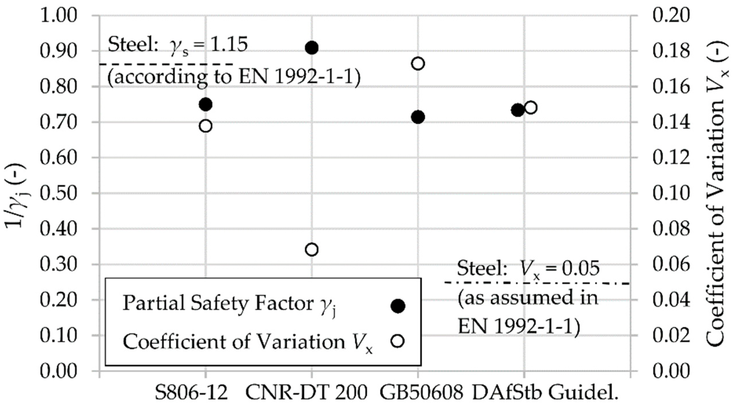
2.2. Strength Reduction and Material Safety Factors for the Different Guidelines

While all guidelines have a consistent approach to the load amplification factors, strength reduction factors are considered in two different ways. The American Concrete Institute (ACI) uses strength reduction factors φ, which multiply the computed overall nominal capacity. In all other standards and guidelines, strength reduction factors or material safety factors γ are applied individually to each of the material components of the members during the calculation of the resistance.
Table 3 shows the strength reduction factors and partial safety factors for FRP materials used by the various guidelines. Furthermore, input values of material properties and additional safety factors from important related standards (e.g., EN 1992-1-1 [19] in case of the Italian code and the German guideline), such as the partial safety factors for concrete and steel, are also introduced.
Figure 3 shows the values of the partial safety factor associated with the FRP jacket, γj, in the various codes. Furthermore, the presumed coefficient of variation Vx of the rupture strain εFRP for the CFRP is also displayed. The coefficient of variation is derived, via iteration, from Equation (6) in accordance with fib (International Federation for Structural Concrete) bulletin 80 [27]:
γ j   =   exp ( 1.645   ·   V x ) exp ( α R   ·   β   ·   V x )   ·   γ Rd 1   ·   γ Rd 2
where αR is the sensitivity factor (αR = 0.8), β is the reliability factor (β = 3.8), γRd1 is a factor accounting for model uncertainties, and γRd2 is a factor accounting for geometrical uncertainties.
For the case of circular CFRP confinement, γRd1 is assumed to be 1.1 and γRd2 is predicted to be 1.0 because of the fact that geometrical uncertainty is limited to the diameter D and minor changes of D can occur without significant discrepancies. Figure 3 shows that reduction due to safety factors varies between 10 and 30%. In addition, the related coefficient of variation Vx probably presumed in codes is noteworthy as well. While the Italian code employs a comparatively low variation of FRP strength, which is comparable to steel, the Chinese GB 50608 assumes a considerably higher Vx. All partial safety factors seem to originate from common axial flat coupon tensile tests. The fact that the factors are also applicable for bending or shear design supports this assumption. This approach is questionable, taking into consideration the significantly different stresses appearing under bending and shear in FRP sheets compared to confinement applications (e.g., Section 2.3). Furthermore, all codes and standards introduce additional factors and partial safety factors depending on the type of composite material, manufacturing process, method of application, and environmental conditions. Table 3 provides an overview.

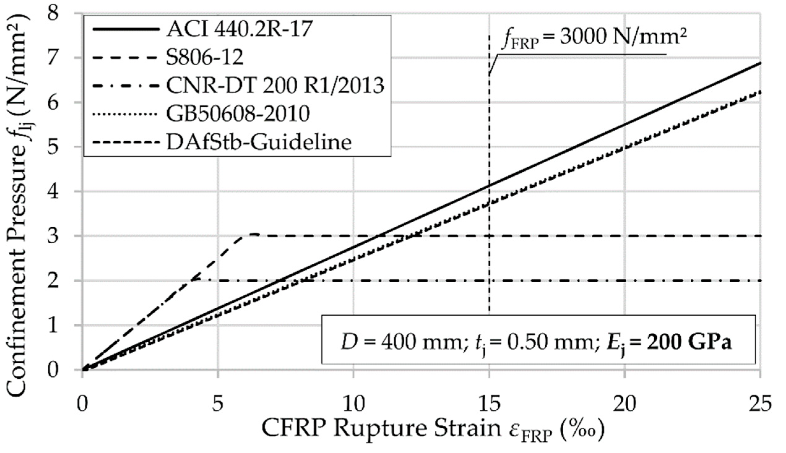
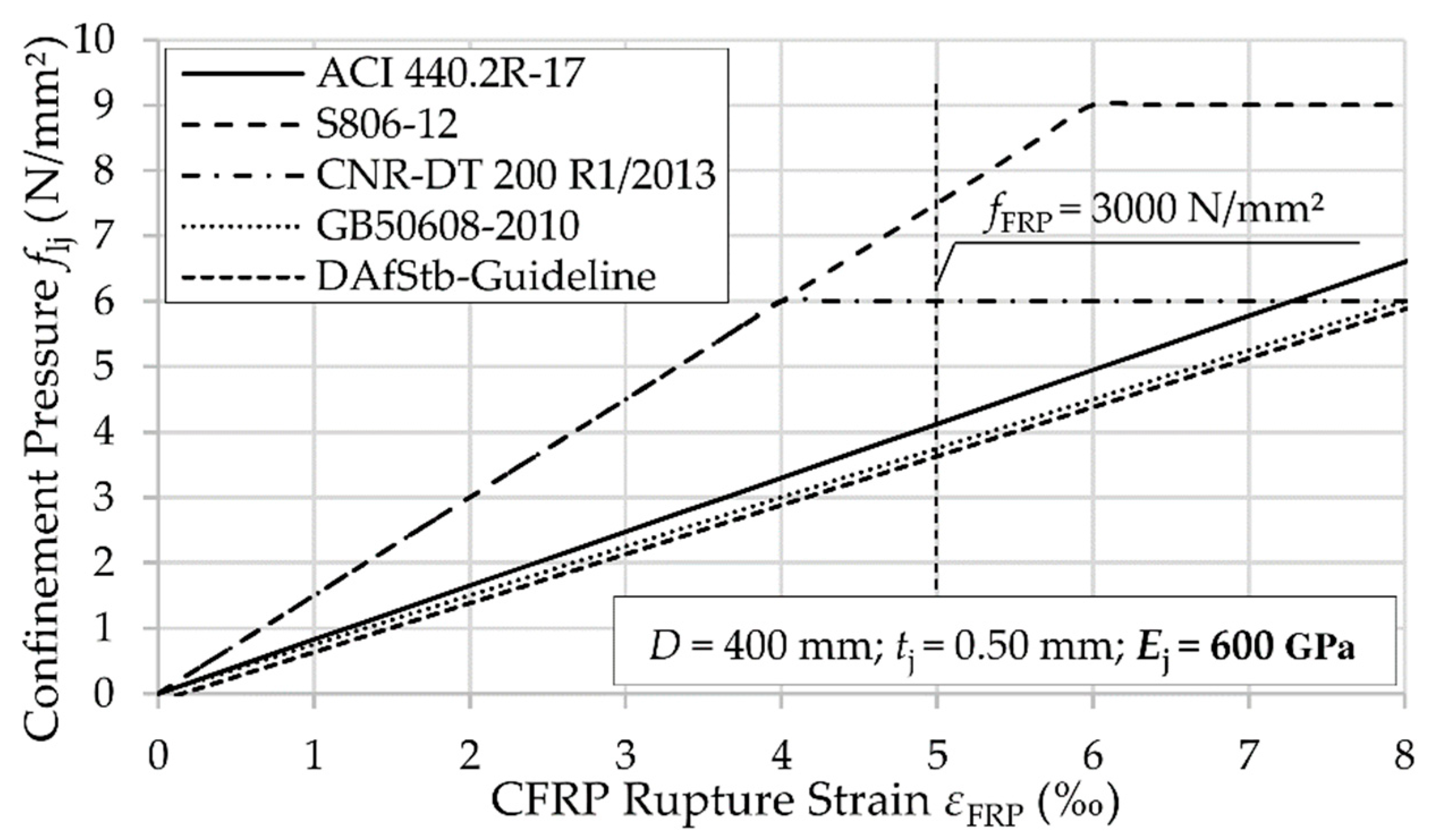
2.3. Rupture Strain of a CFRP Jacket and Confinement Pressure Provided by an FRP Jacket

As indicated by Equation (3), in addition to the column diameter D and the FRP jacket thickness tj, the rupture strain of the CFRP jacket under confinement εju has a very strong impact on the confinement pressure flj. According to the current state of the art, εju should be taken as the actual hoop rupture strain measured in the FRP jacket rather than the FRP materials’ ultimate tensile strain εFRP. The reason for this is that at the rupture of an FRP jacket under confinement, the hoop strain obtained in the jacket εju is generally considerably smaller than the ultimate tensile strain found from flat coupon tensile tests εFRP. On this basis, Lam and Teng [15] established an FRP efficiency factor kε, defined by:
ε ju   =   ε FRP   ·   k ε
In Table 4, different values for kε, proposed in codes and guidelines, are specified. Remarkably, two in five standards still consider kε = 1.0, despite scientific recommendations [28,29]. On the other hand, in ACI 440, kε is recommended as 0.55, and in the Chinese code (CFRP) as well as in the German guideline, kε is assumed to be 0.50. At this point, the DAfStb-Guideline seems to offer the most advanced approach, since the characteristic value kεk is used for design. It is related to the characteristic 5-percentile value obtained from test results and, therefore, it can acknowledge the spreading (material property variation) of the rupture hoop strain for confinement applications. Furthermore, in order to realize a proper and coherent limit state method, a characteristic hoop rupture strain εjuk is deployed.
In fact, the value introduced for kεk = 0.25 seems very low. The reason for this is longitudinal steel reinforcement. Some research groups (e.g., Pellegrino and Modena [30]) proposed that longitudinal reinforcement has an impact on kε due to the fact that external FRP confinement in columns provides additional restraints for vertical steel bars. This leads to further strains concentrated inside the confinement, causing a further reduction of kε Niedermeier [26] followed this proposal and suggested a mean value kε = 0.50 and a characteristic value kεk = 0.25. This procedure was adopted in the DAfStb-Guideline.
In addition to Equation (7), S806-12 and CNR-DT 200 introduced further limits (Table 4). The explanation for these limits was to avoid excessive cracking or loss of shear integrity. Unfortunately, the scientific basis of the limit values is not described further. The Chinese code and German guideline do not suggest any limits.
The implications of the different calculations of εju on flj are shown in Figure 3 and Figure 4 for a circular cross section with D = 400 mm. For comparison purposes, flj was calculated without any strength reduction factor or partial safety factor. In Figure 4, a common elastic modulus Ej = 200 GPa of the composite material was chosen. For a typical maximum FRP strength, fFRP = 3000 N/mm² at 15‰ rupture strain, the calculated flj varies between 2 and 4.2 N/mm². Using the Canadian or Italian codes, the particular complementary limits (Table 4) are decisive. Thus, the achievable flj remains, especially in case of Italian code, far below the pressure levels reached with ACI 440 or GB 50608.
On the contrary, in Figure 5 where Ej = 600 GPA, the results are different. In this case, when fFRP = 3000 N/mm², the confinement pressures vary between 3.5 and 7.5 N/mm². The flj presumed in accordance to S806-12 is twice as high as the flj calculated with the Chinese approach, with the complementary limit not being reached. This leads to the conclusion that in the case of the Italian or Canadian code, an FRP sheet with a high Ej should be chosen, so a high utilization of the FRP material is feasible. This fact is in total opposition to the approaches suggested in ACI 440, GB 50608, and the DAfStb-Guideline.

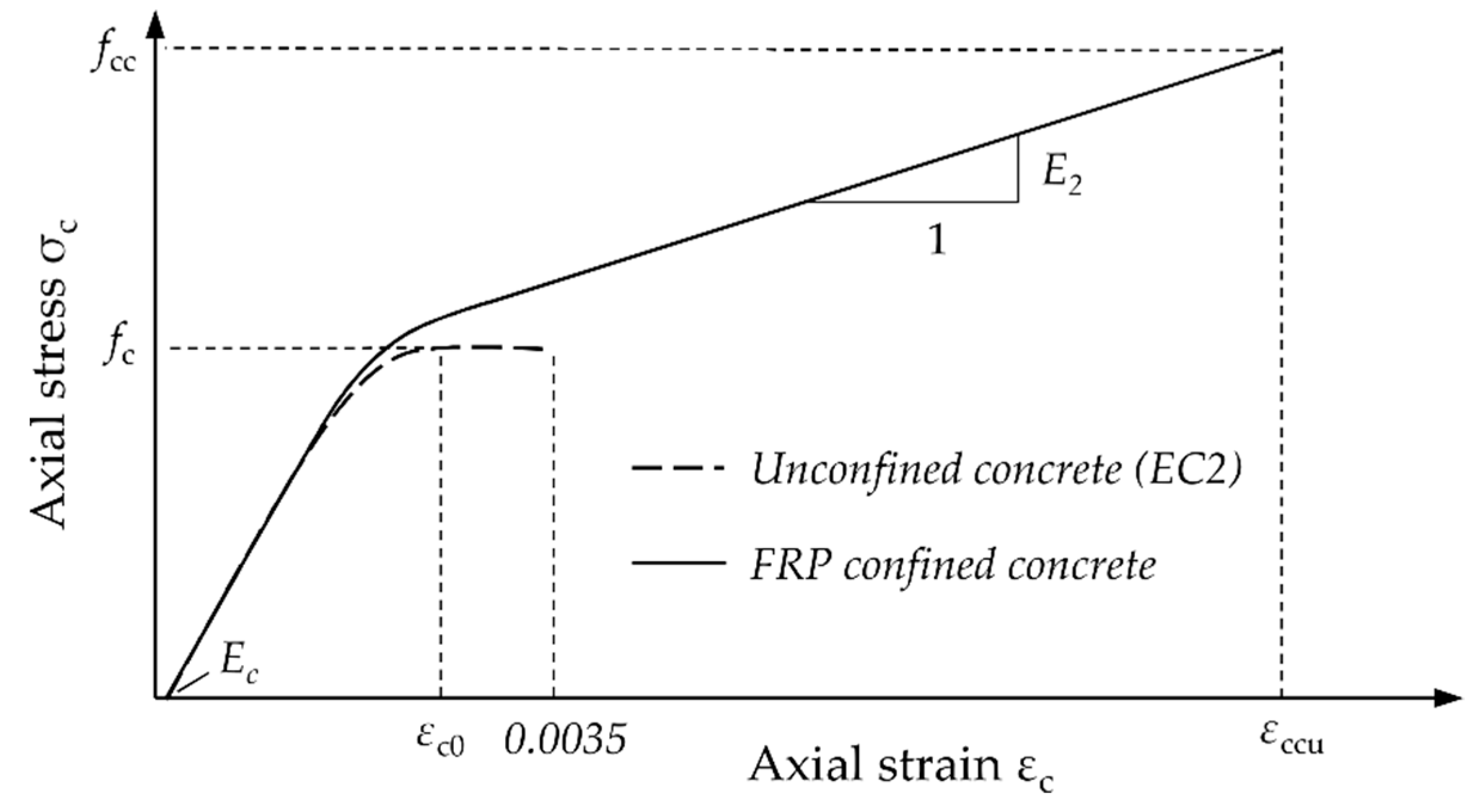
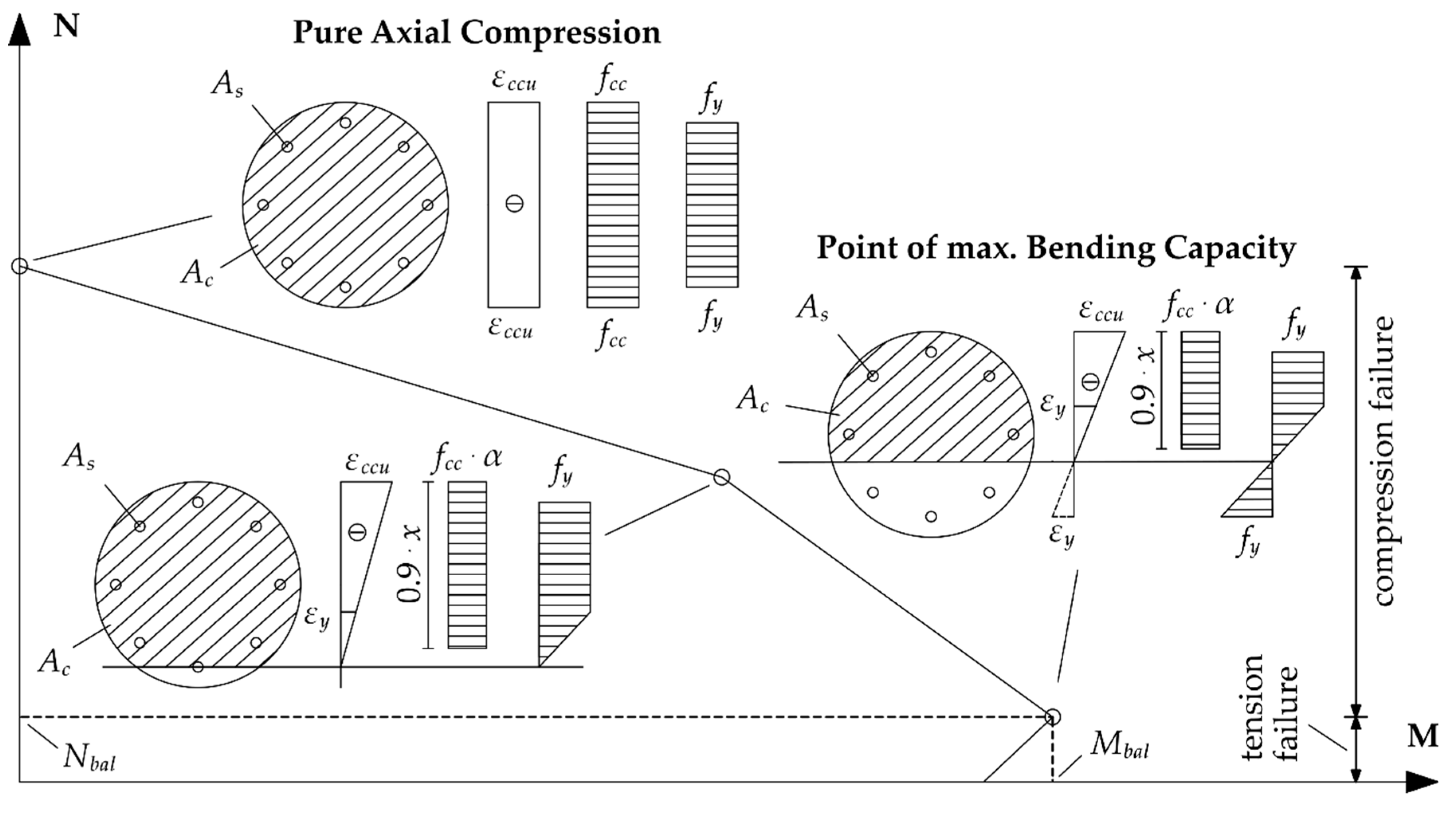
2.4. Maximum Confined Concrete Compressive Strength and Maximum Concrete Strain

2.4.1. Compressive Strength

In Section 1 (Introduction), the common equation to predict the maximum confined concrete compressive strength fcc was introduced (Equation (1)). It is obvious that fcc strongly relies on the factor k1, so Table 5 gives an overview of the k1 introduced in the respective codes and guidelines. Table 5 confirms the fundamental differences among codes regarding the calculation of k1. ACI 440 and the German DAfStb-Guideline propose a constant factor. Such an approach is in accordance with previous studies [15,26]. Interestingly, in DAfStb-Guideline, the characteristic value of k1 is used for design. The other codes deploy the mean value.
In contrast, the Chinese standard introduces the ratio between the stiffness of the FRP jacket and the unconfined characteristic concrete strength fck via βj, to calculate k1. This procedure follows suggestions made by Teng et al. [25]. Incomprehensibly, fck is used for calculation. Especially for old and matured concrete, as expected in the case of strengthening, fck can be considerably smaller if compared to the mean value fc due to higher variability of concrete strength during sampling. Consequently, this approach leads to uncertain results if compared to a procedure where fc is utilized.
In turn, the Canadian code S806-12 identifies the dependence of k1 on flj. This approach is similar to a proposal made by Samaan et al. [31]. In the Italian code, Equation (1) is altered, and k1 must be multiplied by the ratio of the confinement pressure to the unconfined concrete strength. Such a proceeding is similar to findings in Reference [32]. For the calculation of this ratio, the design value fcd = fck/γc is used instead of fc. Again, such a procedure can cause uncertain results if the coefficient of variation of the concrete’s compressive strength is significant.
Finally, Table 5 points out that in five standards and guidelines, four completely different approaches for the assumption of k1 can be found. Furthermore, it is worth mentioning that in the German DAfStb-Guideline, Equation (1) has been altered to implement the consideration of internal transverse reinforcement (ties or spirals) in the calculation of the confinement pressure. This approach is in accordance with proposals released by several researchers, e.g. [33,34,35]. No other standard considers transverse reinforcement.

2.4.2. Concrete Strain

In addition to the increased concrete strength, confinement also leads to a highly increased maximum strain of the confined concrete member. In Table 6, a brief overview is given on how the various standards calculate εccu.
Once more, significant differences between the codes (especially the Canadian approach) are recognizable. However, an accurate value of εccu is mandatory to predict the behavior of a confined column under combined axial compression and bending. This issue is visualized in Figure 6, which describes the strain distribution of a confined RC column at the point of maximum bending capacity (balance point). It shows that εccu, which determines the height of the compression zone xbal and the curvature ϕbal of the column, is important to determine the complementary force eccentricity e2, used to recognize second order effects.

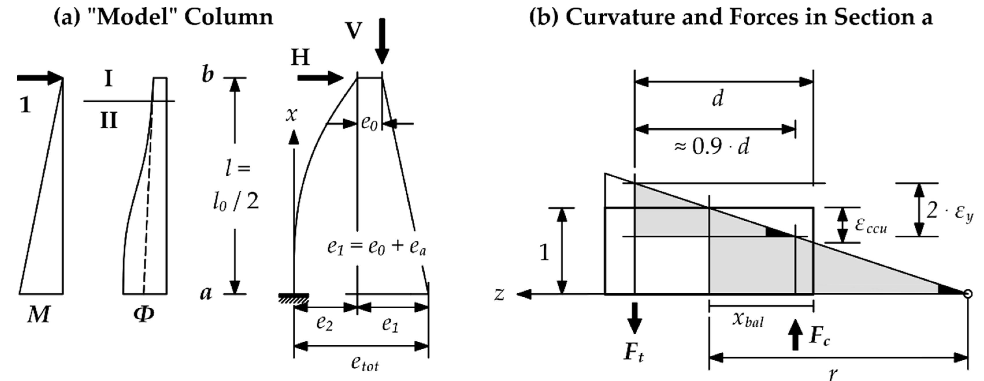
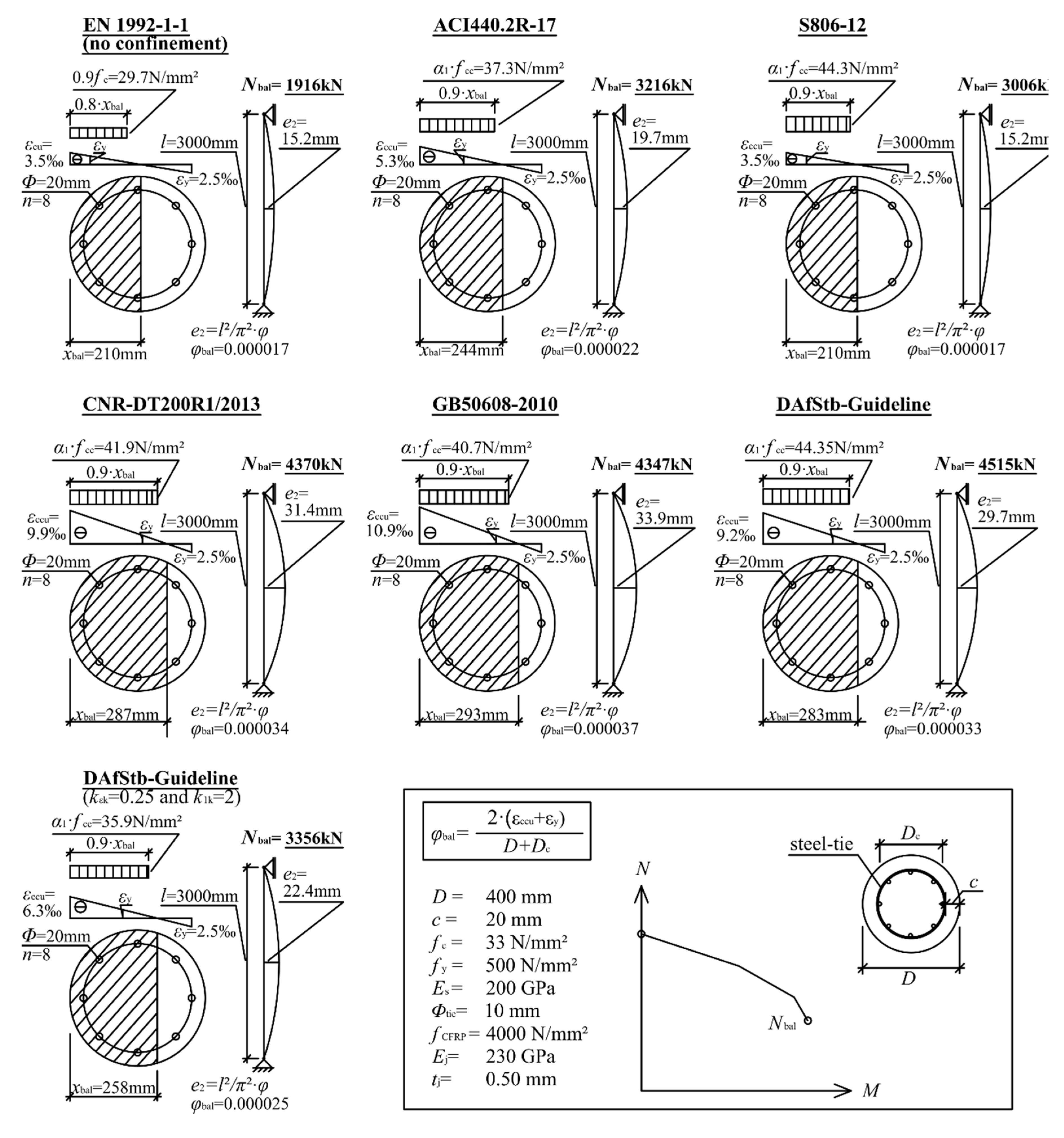
2.5. Example Calculation

In Figure 7, a comparative overview for an example CFRP confined RC column is exhibited, assuming that the column is under combined axial compression and bending. The figure shows the strain distribution according to the particular code or standard, as well as the related stress distribution in the compression zone (stress block calculated according to Equation (5)) at its balance point. In addition, the respective axial load bearing capacity Nbal is mentioned. Finally, the related complementary force eccentricity e2 is displayed to explain the implication of the curvature ϕbal For better classification, the column was designed without CFRP confinement in accordance with EN 1992-1-1 [19]. All calculations were carried out by using mean values of the material properties. Strength reduction or material safety factors were not used. As a particularity, the German DAfStb-Guideline was calculated twice. In the first calculation, the mean values of k1 and kε, in the second case, the characteristic values, k1k and kεk, were used.
Figure 7 reveals a vast range of results calculated for the same basic column. While S806-12 predicts a moderate Nbal and a small e2, the DAfStb-Guideline (mean values) approach leads to an Nbal 2.35 times higher than determined for an unconfined column and predicts an e2 over twice as high as that calculated with S806-12. Then again, the German DAfStb-Guideline approach is the only one to stipulate the usage of characteristic values for k1 and kε.
This fact reduces Nbal by about 25%. The biggest pressure zone is predicted by the Chinese code, covering 78% of the cross section. Due to a low εccu, the Canadian standard reveals the smallest compression zone, covering only 53% of the cross section.

2.6. Conclusion on Current Standards and Guidelines

Finally, it can be concluded that the considered codes and standards provide significantly different approaches to predict confinement effects. Almost all values and equations are dissimilar. This leads to the different and contrary results in design, as presented above.
Major contradictions and dissimilarities are located in:
the definition of the partial safety factors;
the commitment of the FRP efficiency factor kε;
the determination of k1; and
the estimation of the maximum longitudinal concrete strain.
Furthermore, as mentioned earlier, in most cases the additional effects of reinforcing elements, like ties or spirals, cannot be considered. This can be related to the limited experimental data on the field of FRP confined real-size RC columns. These limits have not allowed for the appropriate implementation of key effects in the current models.

3. Experimental Findings

3.1. Current Research Emphasis

The codes and guidelines considered in this paper represent the state of research achieved in 2010. At this time, an extensive research program regarding CFRP confined short concrete columns has been launched at Leipzig University of Applied Sciences. The entire experimental program, further cited and used data from the literature, and particular results are described in References [37,38,39]. Concerning the discrepancies and differences discussed in the previous sections, the program revealed some remarkable findings regarding the crucial rupture strain εju, the entailed partial safety factor γj, the prediction of k1, and the calculation of fcc and εcc for confined plain and reinforced concrete columns.

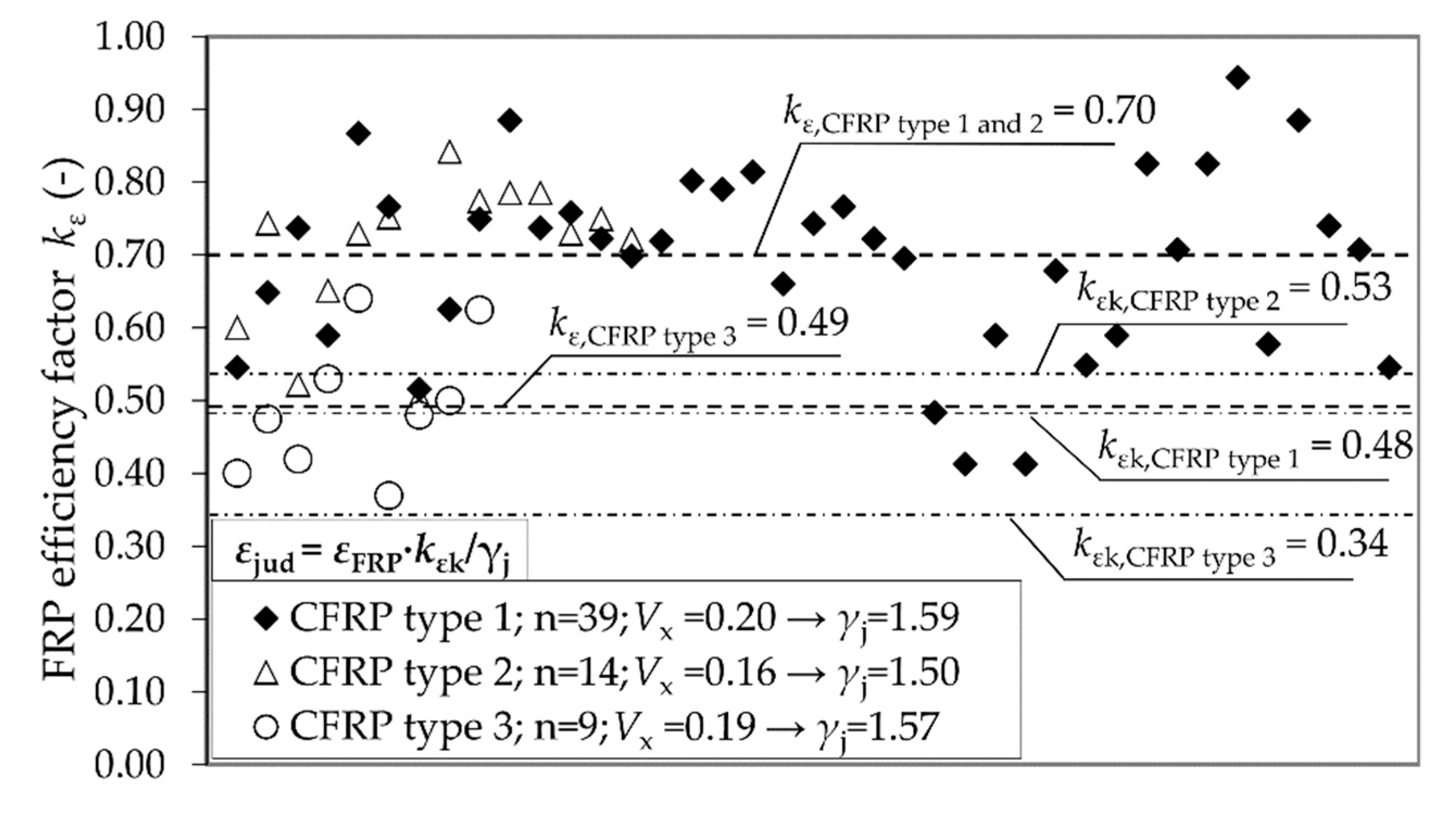
3.2. Results Concerning FRP Rupture Strain of the Jacket and Accompanied Partial Safety Factors

Our own investigations [37] confirmed the proposal of Lam and Teng [15], who suggest working with a reduction factor kε. In almost all cases, the rupture strain reached by the CFRP system was considerably lower than the ultimate tensile strain found from flat coupon tensile tests. Hence, a factor kε < 1.0 should be mandatory. While Lam and Teng—as well as ACI 440, GB 50608, and the DAfStb-Guideline—suggest a common, universally valid reduction factor for CFRP systems; our own tests show that there are significant differences between the carbon fibers used. The average value for three different CFRP systems differed remarkably between kε = 0.49 and kε = 0.70 (Figure 8). Despite a large spread of the test results, it was also possible to obtain characteristic values kεk (in accordance with EN 1990). The test results acknowledged the DAfStb guidelines procedure to work with kεk. The use of a mean value kε, as suggested in GB 50608, can therefore also be uncertain. In summary, efficiency factors should depend on the CFRP material and must be employed carefully.
Our own investigations with CFRP confined reinforced specimens did not confirm the assumption suggested in [26]; that longitudinal reinforcement has an additional, negative effect on εju. In tests, the longitudinal reinforcement remained without impact. It can be concluded that the reduction factor kε stays the same whether longitudinal reinforcement is deployed or not. This tendency was also observed in [40]. Especially in case of the German guideline, this finding leads us to the conclusion that a significant higher kεk of approximately 0.50 (depending on the FRP material) can usually be used in Equation (7). The proposed value of kεk = 0.25 is much too conservative for design matters and provokes an unnecessary loss of load bearing capacity, as seen in Figure 7.
Furthermore, this investigation succeeded in deriving the particular partial factors γj for the utilized CFRP materials. Equation (6) was used for the calculation. As explained in Figure 8, variation coefficients Vx vary remarkably between the CFRP-materials used. Hence, γj varies as well and should be determined separately for each FRP system, for instance within a technical approval procedure.
During the derivation of the displayed partial factors with Equation (6), γRd1 was predicted with a value of 1.20 due to the fact that model uncertainties are very high, but comparable with models for shear design. In contrast, γRd2 was determined with a value of 1.0. For columns with a circular cross section, geometrical uncertainties are small since kε persists at a constant value independent of the column diameter.
Finally, the calculated safety factors are much higher than those suggested by current codes and guidelines (Table 3). The reason for this, as has already been explained in Section 2.1, is that current partial safety factors originate from flat coupon tests only. This is a questionable and potentially unsafe procedure. γj depends on Vx of the FRP jacket’s hoop strain applied to the column perimeter. The same applies to the characteristic values of the FRP strength or FRP rupture strain. To accomplish a proper limit state design method, a value according to Equation (8), instead of a characteristic value derived from flat coupon tests, as used in the Chinese and Italian codes, should be employed:
ε jud   =   ε juk γ j   =   ε FRP   ·   k ε k γ j

3.3. Results for the Maximum Confined Concrete Compressive Strength and Maximum Concrete Strain

As is explained in Section 2.4, current codes and guidelines typically use a factor k1 to predict the influence of the confinement pressure on the confined concrete’s maximum compression strength fcc. In ACI 440 and DAfStb-Guideline a constant factor is used. Nevertheless, research efforts of, for example, Xiao and Wu [4] suggest that, in addition to flj, the unconfined concrete cylinder strength fc is of importance too.
Our own findings confirm these claims. From our work, it is obvious that if flj is deployed in relation to fc, comparably high consistency regressions can be found to explain fcc and εccu. The following equations (Equations (9) and (10)) illustrate our proposal. It should be noted that these equations are designed for a limit state method (calculation of characteristic strength fcck), and that the procedure also enables the consideration of transverse reinforcement (via flk(j+w)):
f cck   =   f ck   +   30   ·   ln   ( f lk ( j + w ) f c )   +   63   if   0.75     f lk ( j + w ) f c     0.125
ε ccu   =   ε c 0   ·   1.75   +   0.05   ·   f lk ( j + w ) f c with   f lk ( j + w ) =   f ljk +   1 2   ·   ρ w   ·   f yk   ·   k e
where fcck = is the characteristic value of the confined concrete strength, flk(j+w) is the characteristic confinement pressure provided by the FRP jacket and the transverse reinforcement, ρw is the ratio of transverse steel to the volume of concrete core, fyk is the characteristic value of yield strength of transverse steel, and ke is a factor to consider the different zones of influence of internal hoops and external FRP jacket (e.g. Table 5→DAfStb-Guideline).
Tests revealed the significant impact of transverse reinforcement. Spirals, in particular, provide a substantial confinement pressure, so the German guideline approach could be confirmed. In Equations (9) and (10), the ratio between confinement pressure and mean value of unconfined concrete strength is introduced, so the spread of fc, as frequently appears in old RC buildings, can be sufficiently considered. This approach can be regarded as safer and more accurate than proceedings that use values like fck or fcd (e.g., GB 50608 or CNR-DT 200).
Moreover, the proposals described in the Chinese and Canadian code (Section 2.4.1) could not be confirmed by our tests. The sole dependency of k1 on the stiffness of FRP confinement (e.g., introduction of the factor βj in GB 50608) or the sole reliance of k1 on flj (e.g., the S 806 approach) could be refuted.

4. Conclusions

Design approaches for FRP confinement of RC columns from five international design guidelines were presented, reviewed, and compared. Besides general information and limitations, the different procedures to predict partial safety factors, the confinement pressure flj, and the design equations for the maximum axial compressive strength fcc and ultimate axial strain εccu of FRP confined RC members with circular cross-sectional shapes were outlined. These investigations revealed significant dissimilarities, leading to different and mostly contrary results among codes and guidelines. These differences may have developed historically, for instance, due to different intensity and prioritization of research in each country. This indicates the need for more intensive exchange, especially between the researchers involved in the standardization process and the determination of unified fundamentals and approaches. It has been shown that some new findings, obtained from elaborate tests carried out at Leipzig University of Applied Sciences, are suitable to improve current approaches. These include suggestions concerning a proper prediction (in accordance with the limit state method) of the crucial FRP hoop strain εju and the entailed partial factor γj. However, further research efforts are still necessary. Notably, loading conditions with combined axial compression and bending have not been sufficiently examined. Therefore, large scale tests with realistic longitudinal and transverse reinforcement, different concrete properties, varying FRP materials, and a proper test setup with sophisticated measurement methods are necessary to fully understand the complex interactions between all reinforcing parts and the strain distribution over the entire cross section during all relevant limit states.

Funding

This research is co-financed by tax revenues on the basis of the budget adopted by the members of the Saxon Parliament (promotion reference: K-7531.20/496-8; SAB no. 100343197). The APC was funded by Leipzig University of Applied Sciences.

Conflicts of Interest

The authors declare no conflict of interest.

References

  1. Matthys, S.; Toutanji, H.; Audenaert, K.; Taerwe, L. Axial Load Behavior of Large-Scale Columns Confined with Fiber-Reinforced Polymer Composites. ACI Struct. J. 2005, 102, 258–267. [Google Scholar]
  2. Lee, J.-Y.; Oh, Y.-J.; Park, J.-S.; Mansour, M.Y. Behavior of Concrete Columns Confined with Steel Spirals and FRP Composites. In Proceedings of the 13th World Conference on Earthquake Engineering, Vancouver, Canada, 1–6 August 2004. [Google Scholar]
  3. Lam, L.; Teng, J.G. Ultimate Condition of Fiber Reinforced Polymer-Confined Concrete. J. Compos. Constr. 2004, 8, 539–548. [Google Scholar] [CrossRef]
  4. Xiao, Y.; Wu, H. Compressive Behavior of Concrete Confined by Various Types of FRP Composite Jackets. J. Reinf. Plast. Compos. 2003, 22, 1187–1201. [Google Scholar] [CrossRef]
  5. Eid, R.; Roy, N.; Paultre, P. Normal- and High-Strength Concrete Circular Elements Wrapped with FRP Composites. J. Compos. Constr. 2009, 13, 113–124. [Google Scholar] [CrossRef]
  6. Rousakis, T.C.; Rakitizis, T.D.; Karabinis, A.I. Design-Oriented Strength Model for FRP-Confined Concrete Members. J. Compos. Constr. 2012, 16, 615–625. [Google Scholar] [CrossRef]
  7. Rousakis, T.C.; Karabinis, A.I. Adequately FRP confined reinforced concrete columns under axial compressive monotonic or cyclic loading. Mater. Struct. 2012, 45, 957–975. [Google Scholar] [CrossRef]
  8. Achillopoulou, D.V.; Rousakis, T.C.; Karabinis, A.I. Square Reinforced Concrete Columns Strengthened Through Fiber Reinforced Polymer (FRP) Sheet Straps. In Proceedings of the 6th International Conference on FRP Composites in Civil Engineering (CICE 2012), Rome, Italy, 13–15 June 2012. [Google Scholar]
  9. Lin, G.; Teng, J.G. Stress-Strain Model for FRP-Confined Concrete in Eccentrically Loaded Circular Columns. J. Compos. Constr. 2019, 23. [Google Scholar] [CrossRef]
  10. Zeng, J.J.; Lin, G.; Teng, J.G.; Li, L.J. Behavior of large-scale FRP-confined rectangular RC columns under axial compression. Eng. Struct. 2018, 174, 629–645. [Google Scholar] [CrossRef]
  11. Ferrotto, M.F.; Fischer, O.; Niedermeier, R. Experimental investigation on the compressive behavior of short-term preloaded carbon fiber reinforced polymer-confined concrete columns. Struct. Concr. 2017, 19, 988–1001. [Google Scholar] [CrossRef]
  12. Pan, Y.; Rui, G.; Li, H.; Tang, H.; Xu, L. Study on stress-strain relation of concrete confined by CFRP under preload. Eng. Struct. 2017, 143, 52–63. [Google Scholar] [CrossRef]
  13. Jiang, C.; Yuan, F.; Wu, Y.-F.; Zhao, X.-M. Effect of Interfacial Bond on Plastic Hinge Length of FRP-Confined RC Columns. J. Compos. Constr. 2019, 23. [Google Scholar] [CrossRef]
  14. Wu, Y.-F.; Jiang, C. Effect of load eccentricity on the stress-strain relationship of FRP-confined concrete columns. Compos. Struct. 2013, 98, 228–241. [Google Scholar] [CrossRef]
  15. Lam, L.; Teng, J.G. Design-Oriented Stress-Strain Model for FRP-Confined Concrete in Rectangular Columns. J. Reinf. Plast. Compos. 2003, 22, 1149–1186. [Google Scholar] [CrossRef]
  16. Jiang, T.; Teng, J.G. Behavior and Design of Slender FRP-Confined Circular RC Columns. J. Compos. Constr. 2013, 17, 443–453. [Google Scholar] [CrossRef] [Green Version]
  17. Jiang, T. FRP-Confined RC Columns. Analysis, Behavior and Design. Ph.D. Thesis, Hong Kong Polytechnic University, Hong Kong, China, 2008. [Google Scholar]
  18. M/515 EN. Mandate for Amending Existing Eurocodes and Extending the Scope of Structural Eurocodes. European Commission, Enterprise and Industry Directorate: Brussels, Belgium, 2012. (Ref. Ares(2012)1516834). Available online: https://eurocodes.jrc.ec.europa.eu/doc/mandate/m515_EN_Eurocodes.pdf (accessed on 10 July 2019).
  19. Eurocode 2: Design of Concrete Structures; EN 1992-1-1; European Committee for Standardization: Brussels, Belgium, 2004.
  20. Design and Construction of Building Structures with Fibre-Reinforced Polymers; CSA S806-2012 (R2017); Canadian Standards Association: Ontario, ON, Canada, 2012; (Reaffirmed 2017).
  21. CNR-DT 200 R1/2013. Guide for the Design and Construction of Externally Bonded FRP Systems for Strengthening Existing Structures. National Research Council—Advisory Committee on Technical Recommendations for Construction: Rome, Italy, 2013. Available online: https://www.cnr.it/en/node/2636 (accessed on 16 June 2019).
  22. Technical code for Infrastructure Application of FRP Composites; GB50608-2010; Ministry of Housing and Urban-Rural Development, General Administration of Quality Supervision, Inspection and Quarantine: Beijing, China, 2010. (In Chinese)
  23. DAfStb-Richtlinie Verstärken von Betonbauteilen mit geklebter Bewehrung; Deutscher Ausschuss für Stahlbeton e. V. (DAfStb): Berlin, Germany, 2012. (In German)
  24. Guide for the Design and Construction of Externally Bonded FRP Systems for Strengthening Concrete Structures; ACI 440.2R-17; American Concrete Institute (ACI): Farmington Hills, MI, USA, 2017.
  25. Teng, J.G.; Jiang, T.; Lam, L.; Luo, Y.Z. Refinement of a Design-Oriented Stress-Strain Model for FRP-Confined Concrete. J. Compos. Constr. 2009, 13, 269–278. [Google Scholar] [CrossRef]
  26. Niedermeier, R. Verstärkung von Stahlbetondruckgliedern durch Umschnürung. Ph.D. Thesis, Technical University of Munich, Munich, Germany, 2009. (In German). [Google Scholar]
  27. FIB Bulletin No. 80. Partial Factor Methods for Existing Concrete Structures; Fédération Internationale du Béton (fib): Lausanne, Switzerland, 2016; ISBN 978-2-88394-120-5.
  28. Smith, S.T.; Kim, S.J.; Zhang, H. Behavior and Effectiveness of FRP Wrap in the Confinement of Large Concrete Cylinders. J. Compos. Constr. 2010, 14, 573–582. [Google Scholar] [CrossRef]
  29. Toutanji, H.; Matthys, S.; Taerwe, L.; Audenaert, K. Behaviour of large-scale columns confined with FRP composites in compression. In Proceedings of the 2nd International Conference on FRP Composites in Civil Engineering (CICE 2004), Adelaide, Australia, 8–10 December 2004. [Google Scholar]
  30. Pellegrino, C.; Modena, C. Analytical Model for FRP Confinement of Concrete Columns with and without Internal Steel Reinforcement. J. Compos. Constr. 2010, 14, 693–705. [Google Scholar] [CrossRef]
  31. Samaan, M.; Mirmiran, A.; Shahawy, M. Model of Concrete Confined by Fiber Composites. J. Struct. Eng. 1998, 124, 1025–1031. [Google Scholar] [CrossRef]
  32. Cui, C.; Sheikh, S.A. Analytical Model for Circular Normal- and High-Strength Concrete Columns Confined with FRP. J. Compos. Constr. 2010, 14, 562–572. [Google Scholar] [CrossRef]
  33. Hu, H.; Seracino, R. Analytical Model for FRP-and-Steel-Confined Circular Concrete Columns in Compression. J. Compos. Constr. 2014, 18. [Google Scholar] [CrossRef]
  34. Eid, R.; Paultre, P. Analytical Model for FRP-Confined Circular Reinforced Concrete Columns. J. Compos. Constr. 2008, 12, 541–552. [Google Scholar] [CrossRef]
  35. Teng, J.G.; Lin, G.; Yu, T. Analysis-Oriented Stress-Strain Model for Concrete under Combined FRP-Steel Confinement. J. Compos. Constr. 2015, 19. [Google Scholar] [CrossRef]
  36. Deutscher Ausschuss für Stahlbeton e. V. Erläuterungen zu DIN EN 1992-1-1 und DIN EN 1992-1-1/NA (Eurocode 2), 1st ed.; Beuth Verlag GmbH: Berlin, Germany, 2012; ISBN 978-3-410-65218-2. (In German)
  37. Käseberg, S. Verstärkung von Stahlbetonstützen mit Kreisquerschnitt durch Umschnürung mit CFK-Werkstoffen. Ph.D. Thesis, Technische University Dresden, Dresden, Germany, 2016. (In German). [Google Scholar]
  38. Käseberg, S.; Holschemacher, K. Dual Confinement of Circular Concrete Columns Consisting of CFRP Sheets and Steel Ties or Spirals. J. Civil. Eng. Archit. Res. 2015, 2, 469–479. [Google Scholar]
  39. Käseberg, S.; Holschemacher, K.; Curbach, M. Zum Tragverhalten CFK-umschnürter Stahlbetonstützen mit Kreisquerschnitt. Beton- und Stahlbetonbau 2018, 113, 505–514. (In German) [Google Scholar] [CrossRef]
  40. Bai, Y.-L.; Dai, J.-G.; Teng, J.G. Buckling of steel reinforcing bars in FRP-confined RC columns: An experimental study. Constr. Build. Mater. 2017, 140, 403–415. [Google Scholar] [CrossRef]
Figure 1. Stress-strain model for FRP confined concrete according to Lam and Teng [15].
Materials 12 02390 g001
Figure 2. Design procedure for a fiber reinforced polymer (FRP) confined reinforced concrete (RC) column subjected to combined compression and bending.
Materials 12 02390 g002
Figure 3. The partial safety factor γj introduced in the designated standard or guideline and the corresponding coefficient of variation Vx.
Materials 12 02390 g003
Figure 4. Confinement pressure flj depicted as a function of CFRP rupture strain εFRP (derived from flat coupon tests) when the modulus of the composite material is Ej = 200 GPa.
Materials 12 02390 g004
Figure 5. Confinement pressure flj depicted as a function of CFRP rupture strain εFRP (derived from flat coupon tests) when the modulus of the composite material is Ej = 600 GPa.
Materials 12 02390 g005
Figure 6. Effect of εccu on the column behavior under combined axial compression and bending [36]. (a) Model representation of a column exposed to normal force and bending moment. (b) Curvature and forces in Section a.
Materials 12 02390 g006
Figure 7. Stress-strain distribution of a CFRP confined RC column at the balance point, according to the considered codes and guidelines.
Materials 12 02390 g007
Figure 8. Values for kε determined from tests with different CFRP materials, calculated characteristic values kεk (according to EN 1990), and partial safety factors γj (according to fib Bulletin 80 [27]).
Materials 12 02390 g008
Table 1. Overview of reviewed standards, codes and guidelines.
TitleCountryPublishing InstitutionIntroducedConfinement Section Length (pages)Reference
ACI 440.2R-17USAAmerican Concrete Institute (ACI)20174[24]
S806-12CanadaCanadian Standards Association (CSA)20121[20]
CNR-DT 200 R1/2013ItalyAdvisory Committee on Technical Recommendations for Construction (CNR)20146[21]
GB 50608-2010ChinaStandardization Administration of the People’s Republic of China20118[22]
DAfStb-GuidelineGermanyGerman Committee for Structural Concrete (DAfStb)20125[23]
Table 2. General information for the various standards, including limitations and the models used.
Standard/GuidelineLoading ConditionLimitationsLimit StateModel
ACI 440.2R-17AC
AC + B
SR-section:
h/b ≤ 2.0; h or b ≤ 900 mm;
fully wrapped only
ULS
SLS
Lam and Teng [15]
S806-12AC + BSR-section:
h/b ≤ 1.5; R ≥ 20 mm;
fully wrapped only
ULSnot specified
CNR-DT 200 R1/2013AC
AC + B
SR-section:
h/b ≤ 2.0; h or b ≤ 900 mm;
discontinuous wrapping:
sD/2
ULSnot specified
GB 50608-2010AC + BSR-section:
h/b ≤ 1.5; h or b ≤ 600 mm; R ≥ 20 mm;
fully wrapped only
ULSTeng et al. [25];
Jiang [17]
DAfStb-GuidelineAC + Bcircular only:
D ≥ 120 mm; λ ≤ 40; e0/D ≤ 0.25
fc ≤ 58 N/mm²;
fully wrapped only
ULS
SLS
Niedermeier [26];
Jiang [17]
Abbreviations: AC = pure axial compression; AC + B = combined axial compression and bending; ULS = ultimate limit state; SLS = serviceability limit state; SR = noncircular cross section; R = corner radius; h = height and b = width for rectangular cross sections, s = net distance between FRP strips, D = diameter of circular cross section, λ = column slenderness, e0/D = maximum eccentricity, fc = unconfined concrete strength.
Table 3. Strength reduction and material safety factors.
Standard/GuidelineInput ValueStrength Reduction or Partial Safety FactorPartial Safety Factor EnvironmentAdditional Factor
ACI 440.2R-17mean valuesφ = 0.75 (spiral);
φ = 0.70 (steel-tie)
CE for C, G, or A under I, E, or AggΨf = 0.95
S806-12mean valuesγj = 0.75; γc = 0.65;
γs = 0.85
not usednot used
CNR-DT 200 R1/2013characteristic valuesγj = 1.10; γc = 1.50;
γs = 1.15
ηa for C, G, or A under I, E, or AggγRd = 1.10
GB 50608-2010characteristic valuesγj = 1.40γe for C, G, B, or A under I, E, or Aggnot used
DAfStb-Guidelinecharacteristic valuesγj = 1.35; γc = 1.50;
γs = 1.15
αT = 0.70 (temperature);
αE = 1.00 (loading);
αF = 1.00 (moisture);
αZ = 0.75 (loading duration)
αcc = 0.85
Abbreviations: C = Carbon, G = Glass, A = Aramid, B = Basalt, I = interior, E = exterior, Agg = aggressive environment. γj = safety factor FRP jacket, γc = safety factor concrete, γs = safety factor steel, γRd = safety factor to consider model uncertainties, αcc = further conversion factor for concrete, CE, ηa, and γe = environmental reduction factors according to particular code, αT, αE, αF, and αZ = reduction factors to address environmental as well as loading conditions according to DAfStb-Guideline, Ψf = additional reduction factor.
Table 4. Efficiency factor kε and complementary limits for predictions of the hoop strain εju in FRP jacket.
Standard/GuidelineEfficiency Factor kεCharacteristic Value kεkRupture Hoop Strain ModelFurther Limit
ACI 440.2R-170.55not usedεju = kε · εFRP · CEεju ≤ 0.004 if AC + B
S806-121.00not usedεjud = γj · εFRPεjud ≤ 0.006
CNR-DT 200 R1/20131.00not usedεjud= ηa · εFRP,k/γjεjud ≤ 0.004
GB 50608-20100.50 (CFRP)
0.70 (GFRP)
not usedεjud= kε · εFRP,k/(γj · γe)not used
DAfStb-Guideline0.500.25εjuk= kεk · εFRP,k · αT · αE · αF · αZnot used
Abbreviations: CFRP = carbon fiber reinforced polymer, GFRP = glass fiber reinforced polymer, AC + B = combined axial compression and bending, εFRP = mean value of maximum strain for an FRP sheet, εFRP,k = characteristic maximum strain for an FRP sheet, εjuk = characteristic hoop rupture strain in FRP jacket at column, εjud = design hoop rupture strain.
Table 5. The factor k1 determined in the considered codes and guidelines.
Standard/GuidelineFactor k1Factor k1kParticularities
ACI 440.2R-173.30not usedadditional, k1 is multiplied with Ψf
S806-126.70 · (flj)−0.17not usedno
CNR-DT 200 R1/20132.60not usedinstead of flj, k1 is multiplied with fcd · (fljd/fcd)2/3
GB 50608-20103.50not usedadditional, k1 is multiplied with (1–6.5/βj);
βj = (Ej · tj)/(fck · D/2)
DAfStb-Guideline3.662.00instead of flj, k1 is multiplied with (fljk + (ρw · fyk−Δp) · ke);
ke = ((Dcs/2)/D)2
Abbreviations: fck = characteristic concrete strength, fcd = design concrete strength, fljk = char. FRP jacket strength, fljd = design FRP jacket strength, ρw = ratio of transverse reinforcement, fyk = is the characteristic value of yield strength of transverse steel, Δp = pressure gradient between internal reinforcement and FRP jacket, Dc = diameter of core of section enclosed by transverse reinforcement, s = center to center spacing of circular hoop.
Table 6. Approaches suggested in codes and guidelines to predict the maximum concrete strain.
Standard/GuidelineApproachFactors/Particularities
ACI 440.2R-17Equation (2)k2 = 1.50, k3 = 12, k4 = 0.45; εccu ≤ 0.01
S806-12not provided (refer to CAN/CSA-A23.3→εccu = 0.0035)no
CNR-DT 200 R1/2013 ε ccu   =   0.0035   +   0.015   ·   f ljd f cd for calculation of fljd ε jud     0.6   ·   ε FRP , k
GB 50608-2010 ε ccu   =   0.0033   +   0.60   ·   β j 0.8   ·   ε jud 1.45 no
DAfStb-GuidelineEquation (2)k2 = 1.75, k3 = 19, k4 = 0; in Equation (2):
(flj/fc) is replaced by (fljk/fc)
Abbreviations: fck = characteristic concrete strength, fcd = design concrete strength, fljk = characteristic FRP jacket strength, fljd = design FRP jacket strength, ϵ FRP ,   k = characteristic maximum strain for an FRP sheet.

