Laboratory-Based Investigation into Stress Corrosion Cracking of Cable Bolts


Abstract
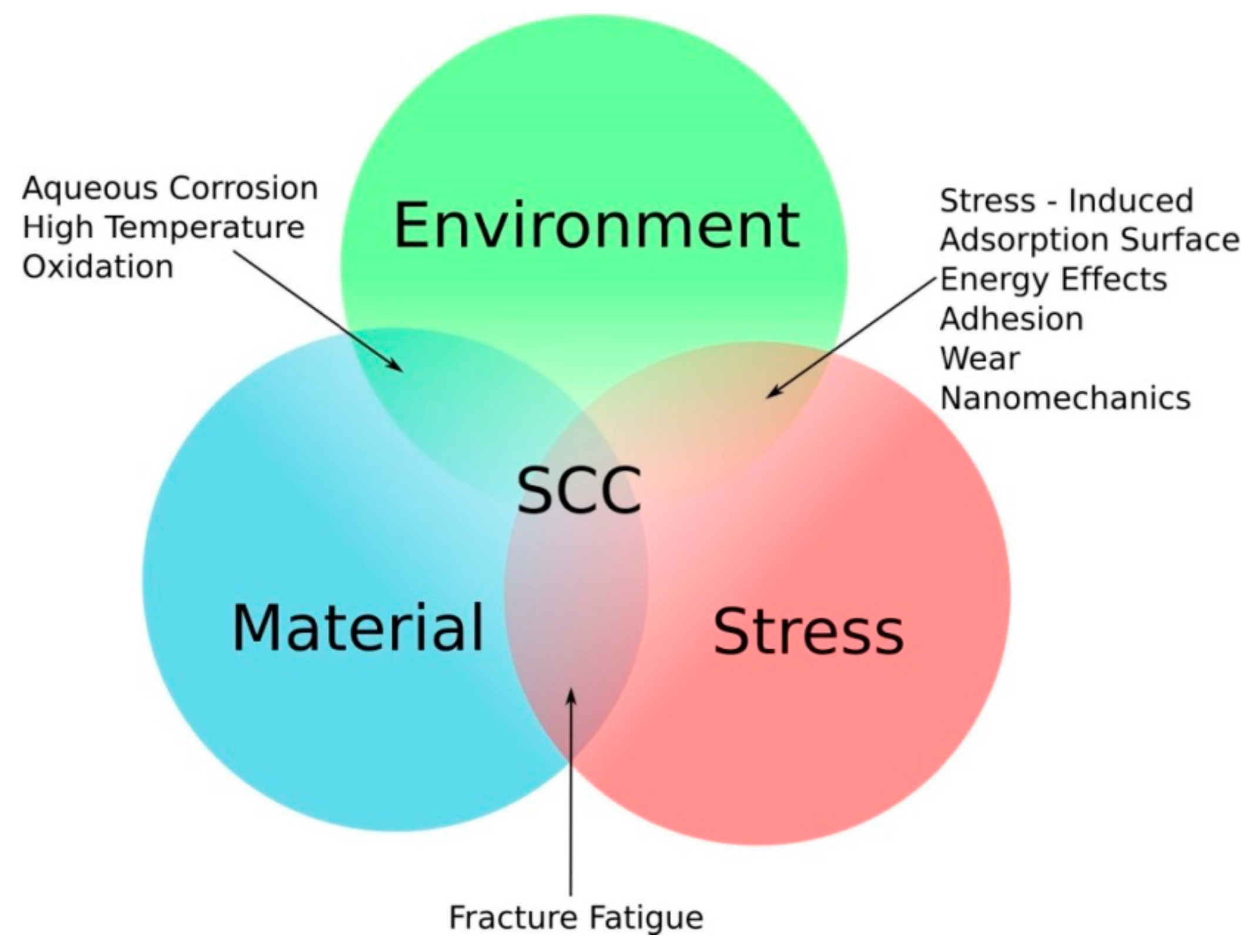
:1. Introduction
2. Experimental Programs
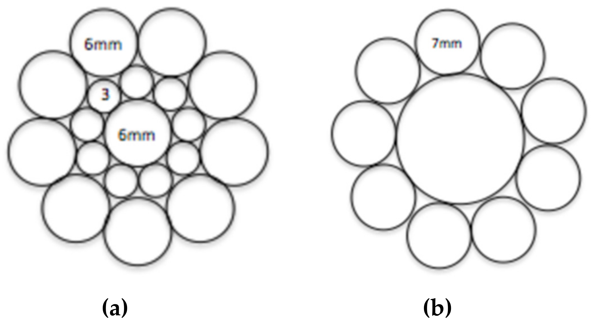
2.1. Testing Specimens
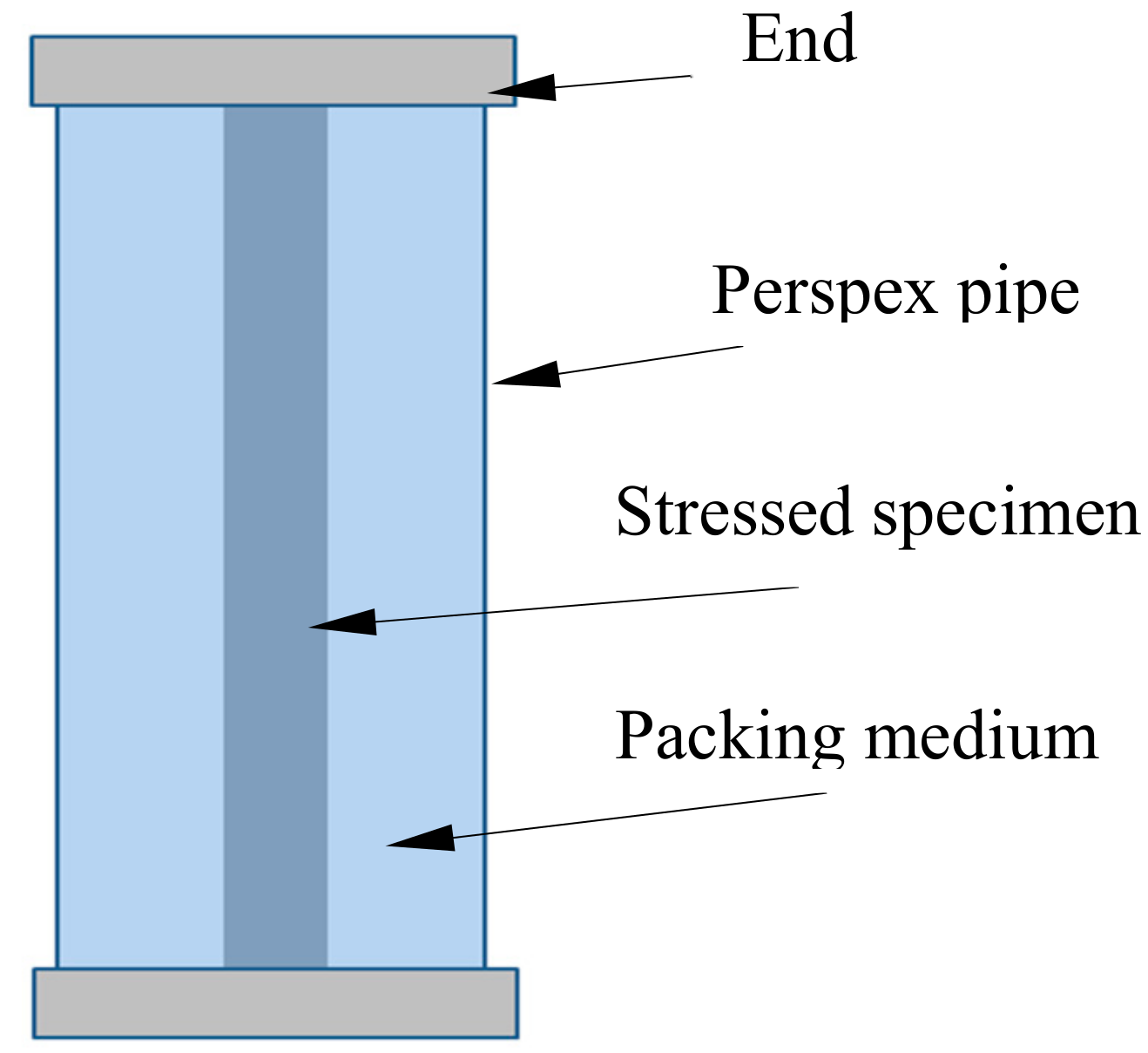
2.2. Long-Term Cable-Bolt Coupon Tests
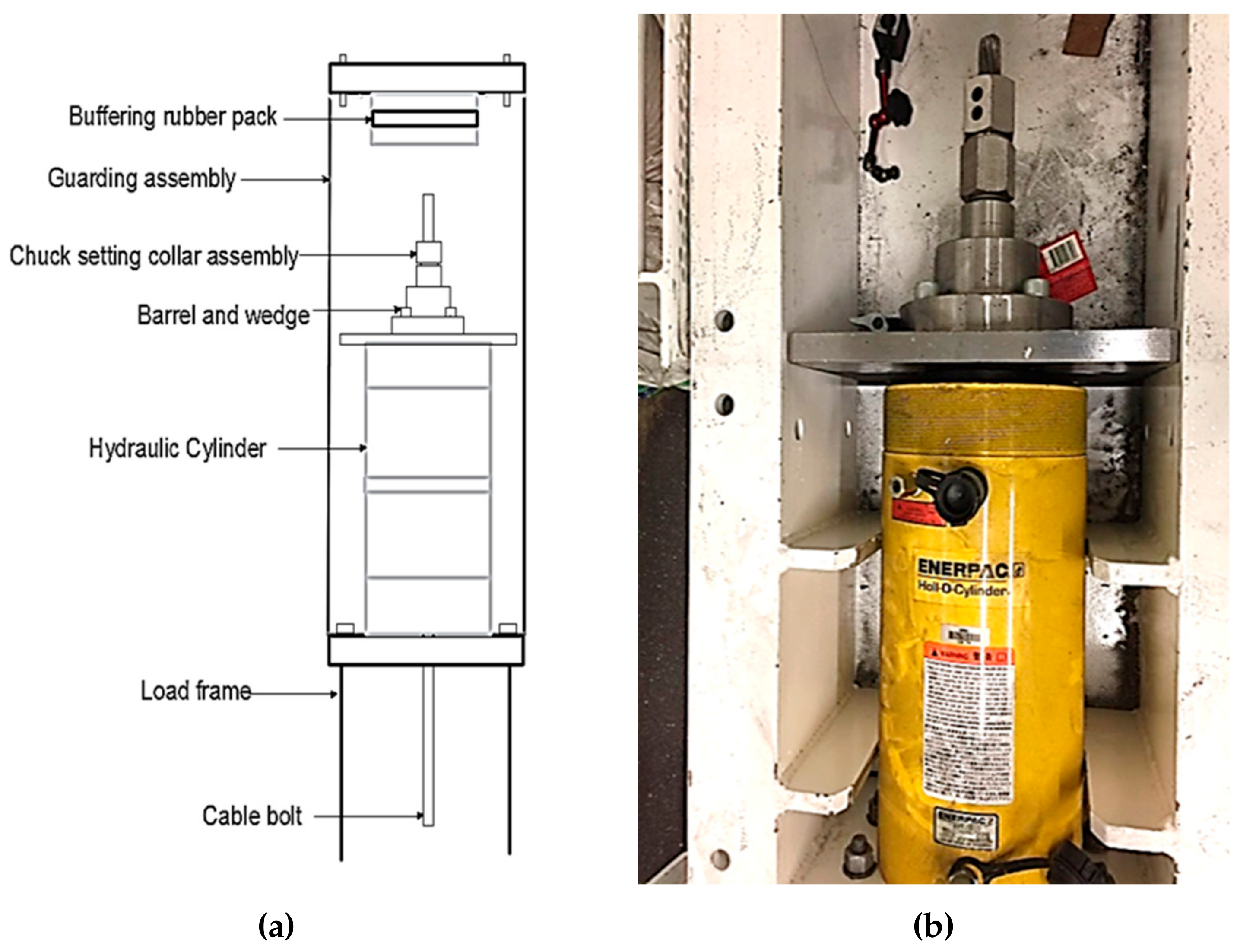
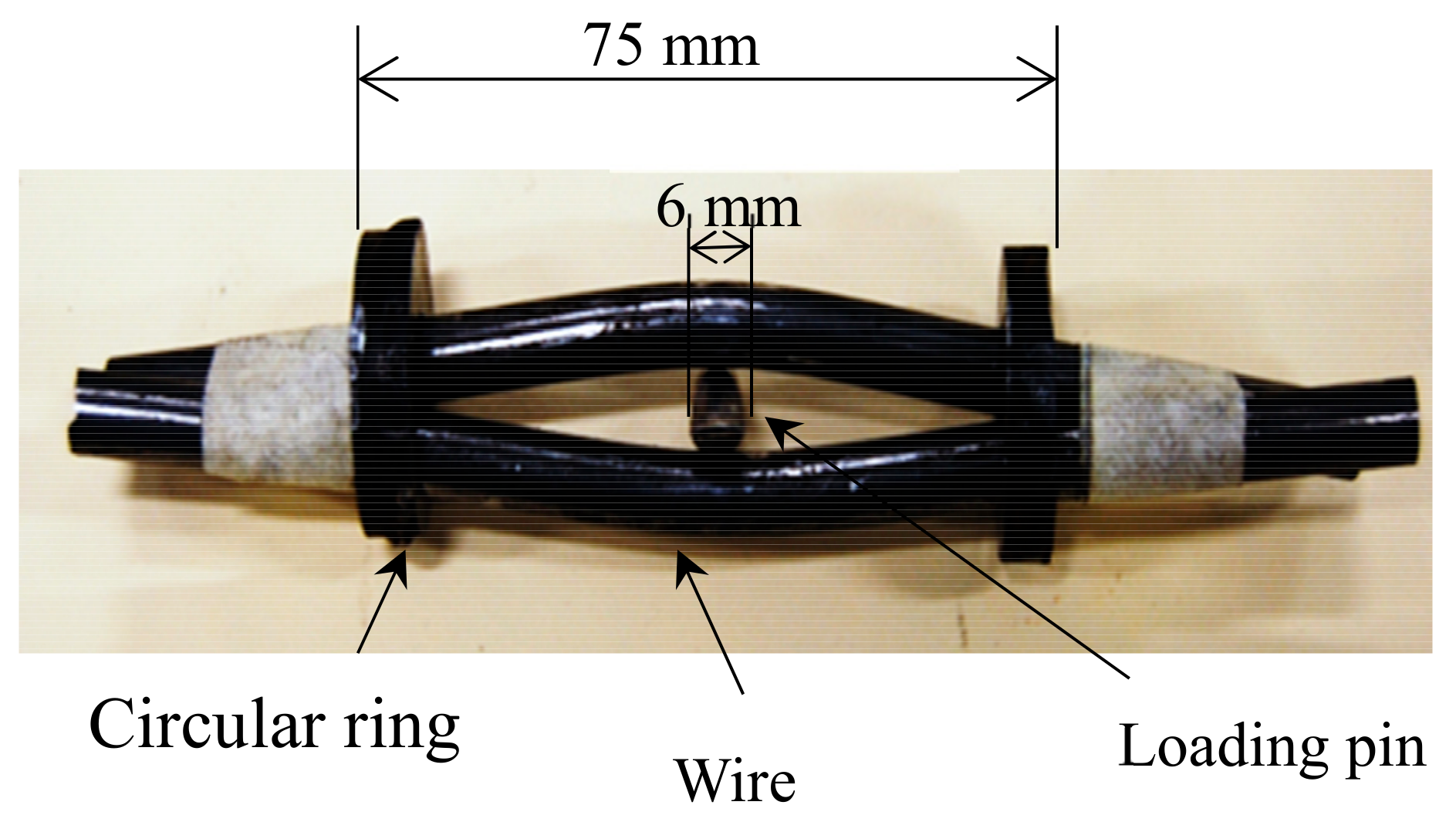
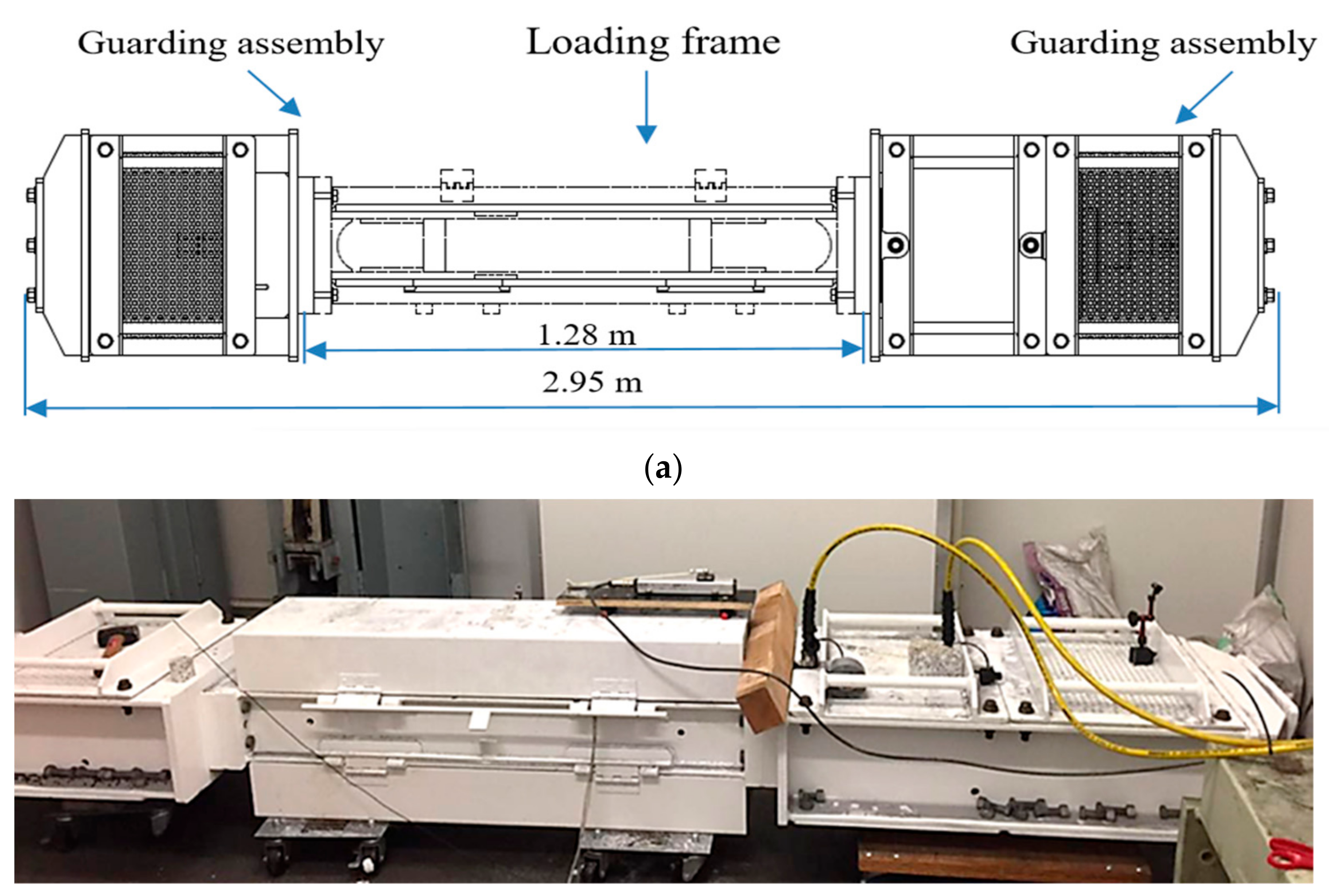
2.3. Accelerated Full-Scale Cable-Bolt Tests
3. Results and Analysis
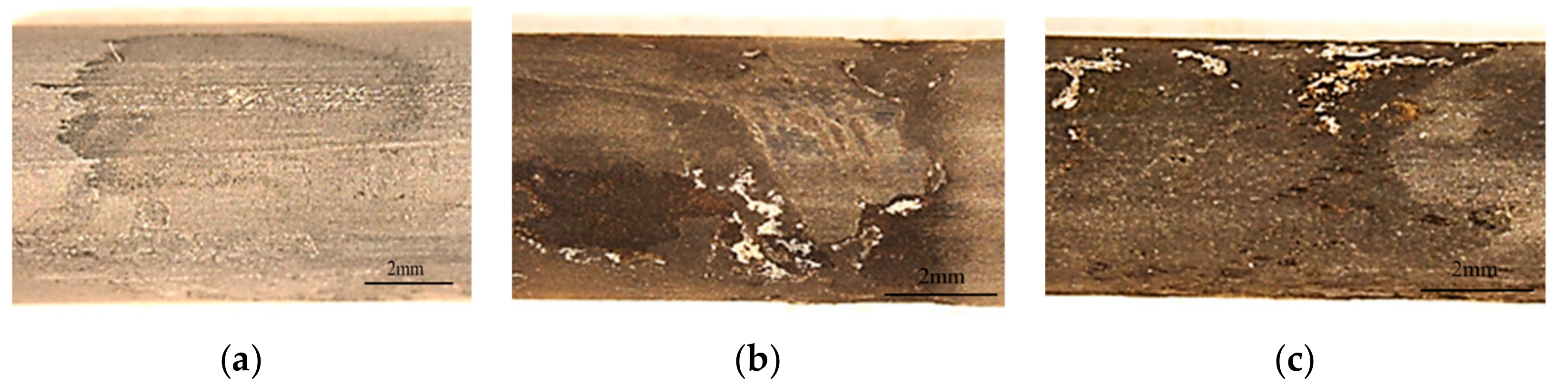
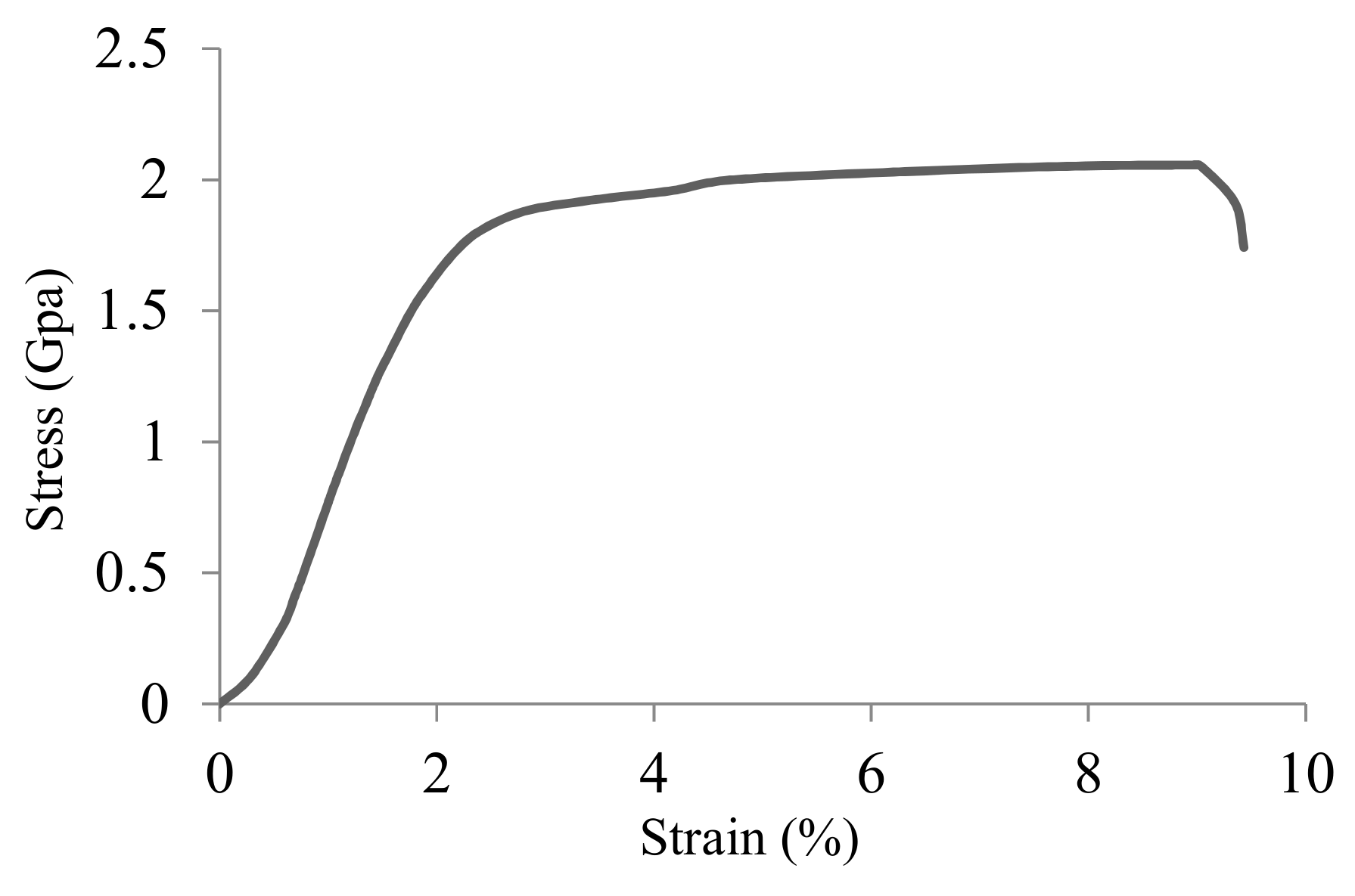
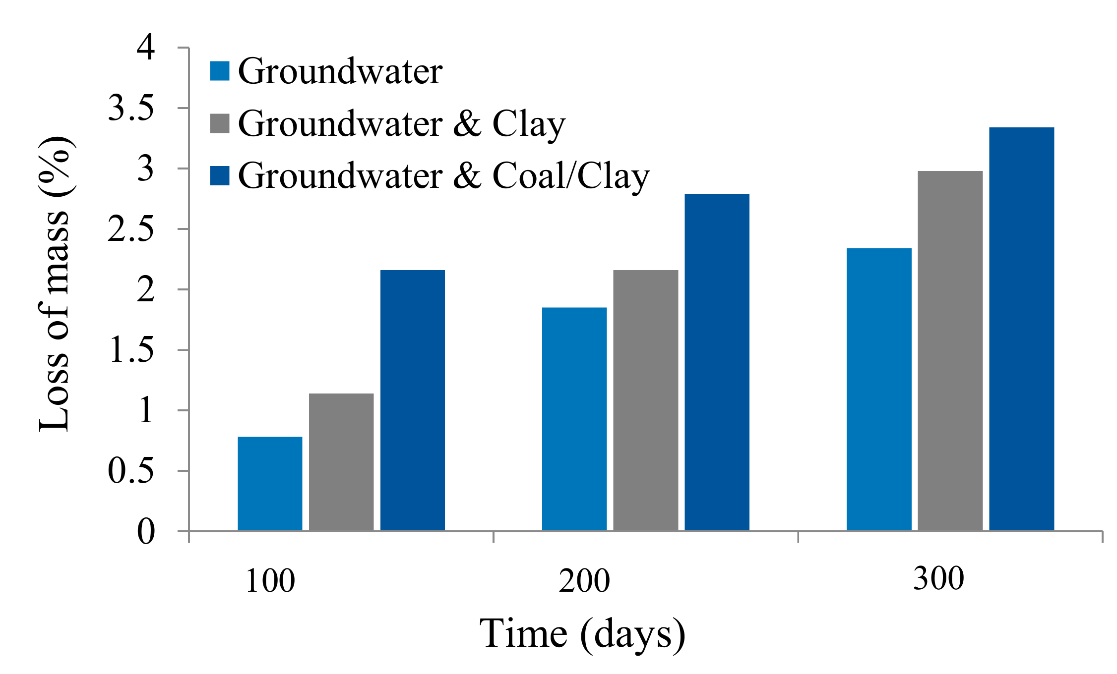
3.1. Long-Term Cable-Bolt Coupon Tests
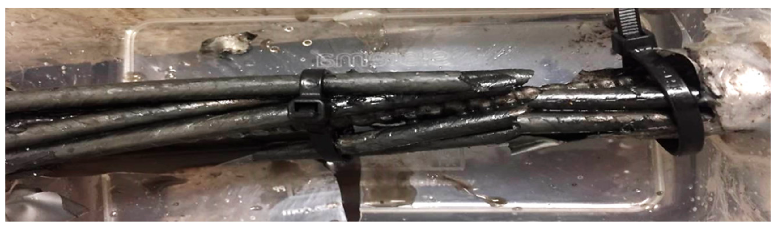
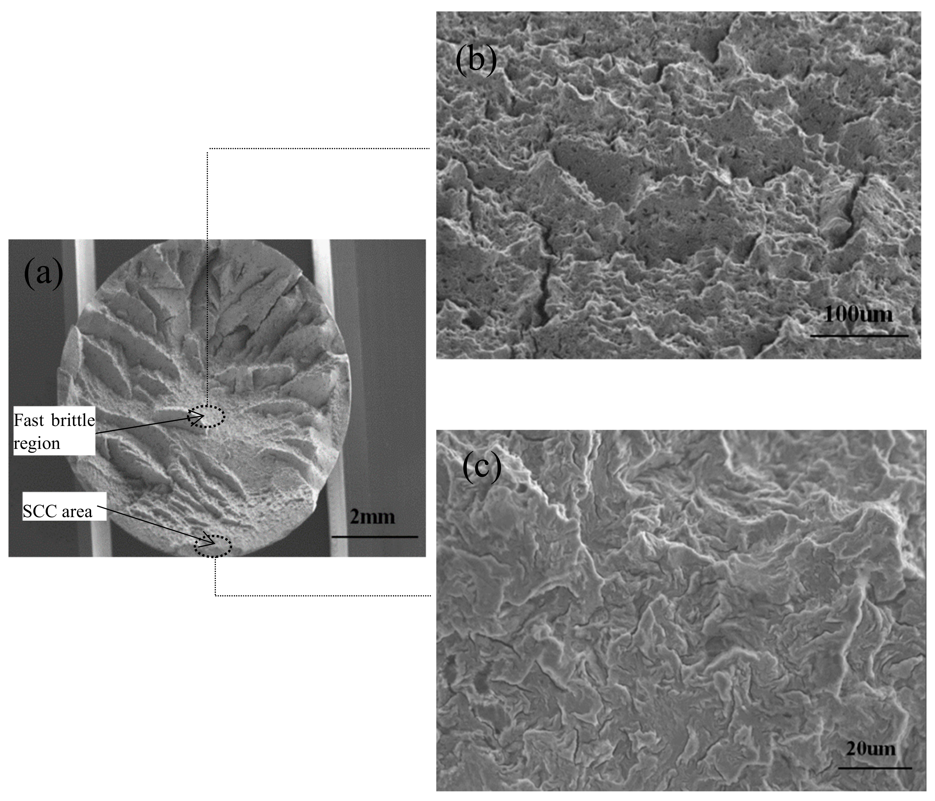
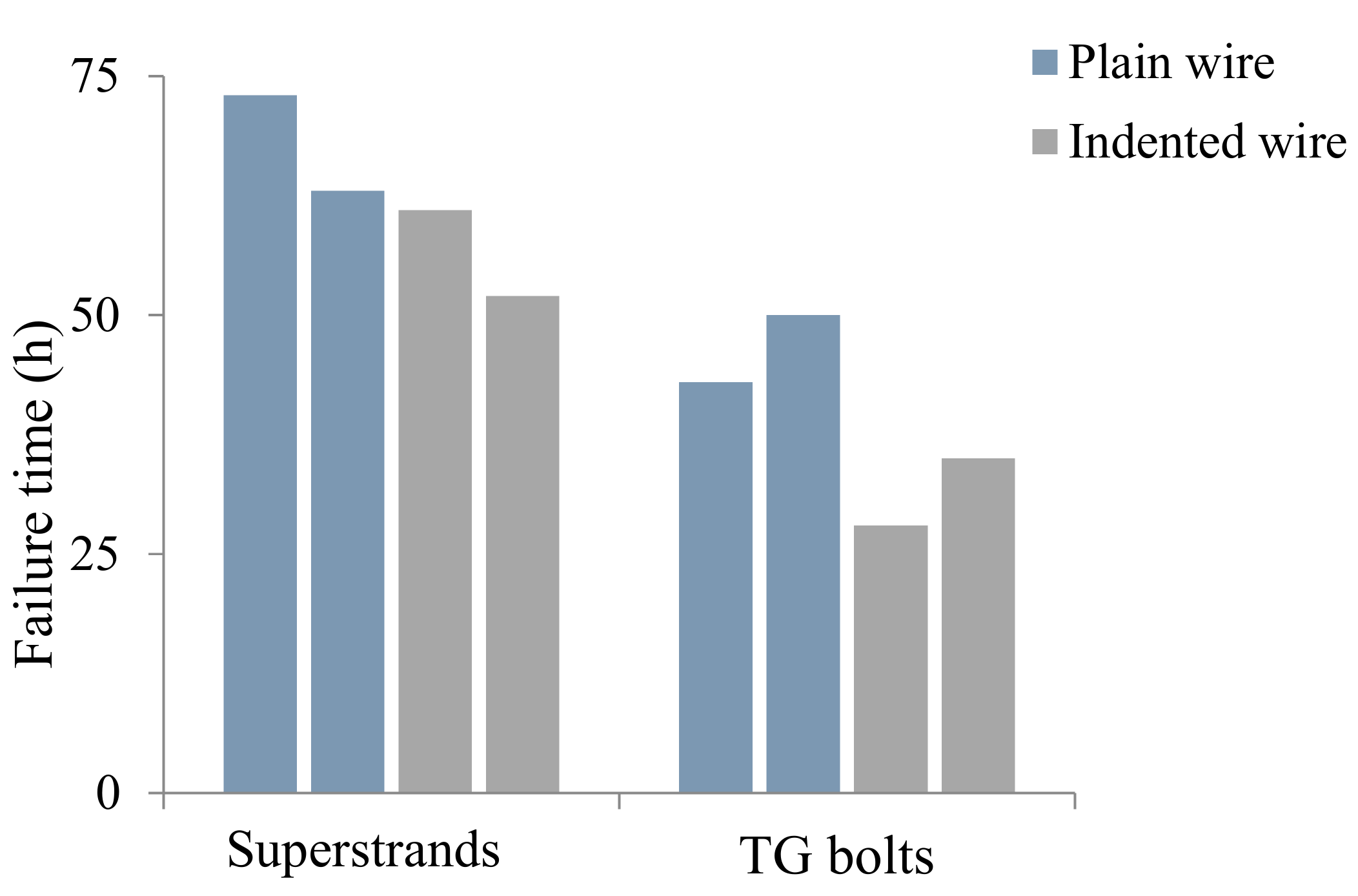
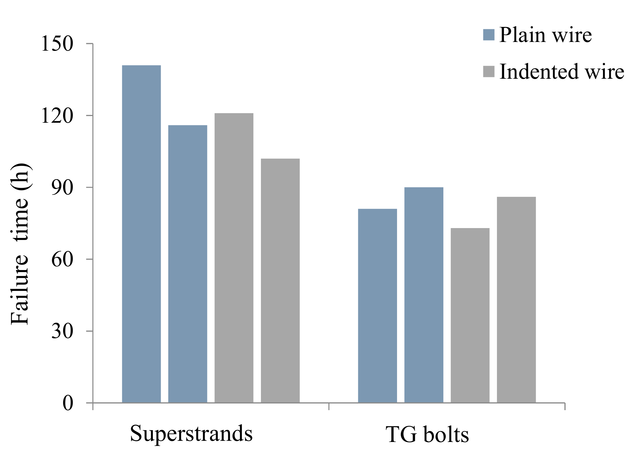
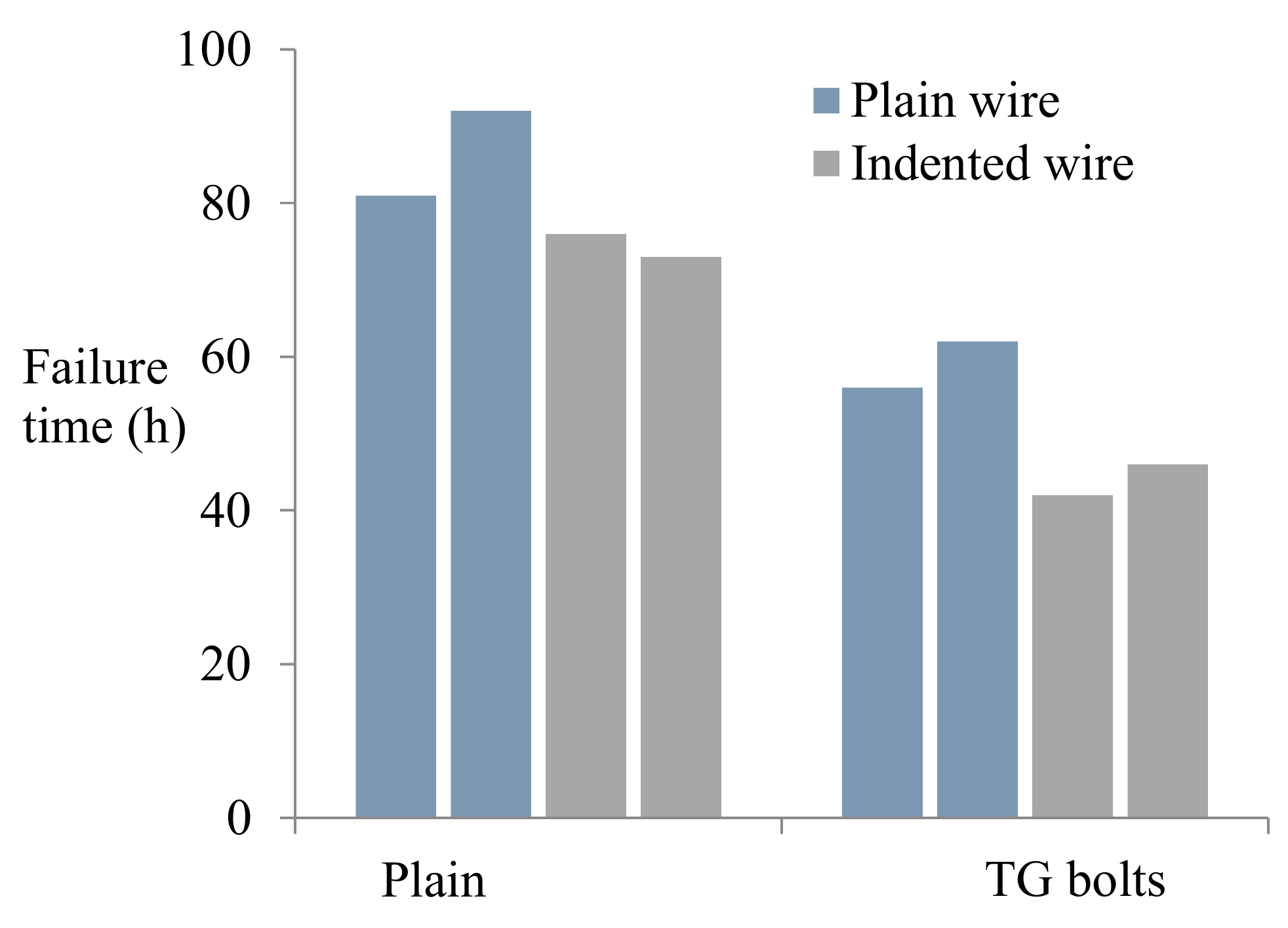
3.2. Accelerated Full-Scale Cable-Bolt Tests
4. Conclusions
Author Contributions
Funding
Acknowledgments
Conflicts of Interest
References
- Guo, G.Y.; Kang, H.P.; Qian, D.Y.; Gao, F.Q.; Wang, Y. Mechanism for Controlling Floor Heave of Mining Roadways Using Reinforcing Roof and Sidewalls in Underground Coal Mine. Sustainability 2018, 10, 1413. [Google Scholar] [CrossRef]
- Li, Y.; Sun, S.; Tang, C.A. Analytical Prediction of the Shear Behaviour of Rock Joints with Quantified Waviness and Unevenness Through Wavelet Analysis. Rock Mech. Rock Eng. 2019, 1–13. [Google Scholar] [CrossRef]
- Kılıc, A.; Yasar, E.; Celik, A.G. Effect of grout properties on the pull-out load capacity of fully grouted rock bolt. Tunn. Undergr. Space Technol. 2002, 17, 355–362. [Google Scholar] [CrossRef]
- Wu, S.; Northover, M.; Craig, P.; Canbulat, I.; Hagan, P.C.; Saydam, S. Environmental influence on mesh corrosion in underground coal mines. Int. J. Min. Reclam. Environ. 2018, 32, 519–535. [Google Scholar] [CrossRef]
- Nie, X.; Wei, X.; Li, X.; Lu, C. Heat Treatment and Ventilation Optimization in a Deep Mine. Adv. Civ. Eng. 2018, 2018, 1–12. [Google Scholar] [CrossRef]
- Li, Y.; Wu, W.; Sun, S.; Tang, C.; Liu, B. Predicting the shear characteristics of rock joints with asperity degradation and debris backfilling under cyclic loading conditions. Int. J. Rock Mech. Min. Sci. 2019, 120, 108–118. [Google Scholar] [CrossRef]
- Windsor, C. A review of long, high capacity reinforcing systems used in rock engineering. In Ground Support in Mining & Underground Construction, Proceedings of the Fifth International Symposium on Ground Support, Perth, Australia, 28–30 September 2004; CRC Press: Boca Raton, FL, USA, 2004; pp. 17–41. [Google Scholar]
- Toribio, J.; Valiente, A. Failure analysis of cold drawn eutectoid steel wires for prestressed concrete. Eng. Fail. Anal. 2006, 13, 301–311. [Google Scholar] [CrossRef]
- Atienza, J.; Ruiz-Hervias, J.; Elices, M. The role of residual stresses in the performance and durability of prestressing steel wires. Exp. Mech. 2012, 52, 881–893. [Google Scholar] [CrossRef]
- Toribio, J.; González, B.; Matos, J. Fatigue and fracture paths in cold drawn pearlitic steel. Eng. Fract. Mech. 2010, 77, 2024–2032. [Google Scholar] [CrossRef]
- Elias, E.; Vandermaat, D.; Crosky, A.; Saydam, S.; Hagan, P.; Hebblewhite, B.; Craig, P. Environmental characterization of the stress-corrosion cracking of rockbolts in underground coal mines using laboratory and in-situ testing. In RapidMiner: Data Mining Use Cases and Business Analytics Applications, Proceedings of the ISRM International Symposium—EUROCK 2013, Wroclaw, Poland, 23–26 October 2013; Chapman and Hall: London, UK, 2013. [Google Scholar]
- Vandermaat, D.; Elias, E.; Craig, P.; Saydam, S.; Crosky, A.; Hagan, P.; Hebblewhite, B. Experimental protocol for stress corrosion cracking of rockbolts. In Proceedings of the 12th Underground Coal Operators’ Conference, Wollongong, Australia, 17 February 2012. [Google Scholar]
- Oliveira, D.; Diederichs, M.S. Tunnel support for stress induced failures in Hawkesbury Sandstone. Tunn. Undergr. Sp. Tech. 2017, 64, 10–23. [Google Scholar] [CrossRef]
- Lynch, S. Environmentally assisted cracking: Overview of evidence for an adsorption-induced localised-slip process. Acta Metall. 1988, 36, 2639–2661. [Google Scholar] [CrossRef]
- Gray, P. Stress corrosion cracking of rock bolts. In Proceedings of the First Coal Operators’ Conference, Wollongong, Australia, 13–15 February 1998. [Google Scholar]
- Hebblewhite, B.; Fabjanczyk, M.; Gray, P. Investigations Into Premature Rock Bolt Failures in the Australian Coal Mining Industry. In Proceedings of the 2003 Coal Operators’ Conference, Wollongong, Australia, 12–14 February 2003. [Google Scholar]
- Crosky, A.; Smith, B.; Hebblewhite, B. Failure of rockbolts in underground mines in Australia. Pract. Fail. Anal. 2003, 3, 70–78. [Google Scholar] [CrossRef]
- Gamboa, E.; Atrens, A. Environmental influence on the stress corrosion cracking of rock bolts. Eng. Fail. Anal. 2003, 10, 521–558. [Google Scholar] [CrossRef]
- Villalba, E.; Atrens, A. An evaluation of steels subjected to rock bolt SCC conditions. Eng. Fail. Anal. 2007, 14, 1351–1393. [Google Scholar] [CrossRef]
- Vandermaat, D.; Saydam, S.; Hagan, P.C.; Crosky, A.G. Examination of rockbolt stress corrosion cracking utilising full size rockbolts in a controlled mine environment. Int. J. Rock Mech. Min. Sci. 2016, 81, 86–95. [Google Scholar] [CrossRef]
- McCafferty, E. Introduction to Corrosion Science; Springer-Verlag: New York, NY, USA 2010. [Google Scholar]
- Parrot, R. An Investigation into the Effects of Corrosion on the Mechanical Properties of AT Strata Bolts; Report CN96/110/HSE; Independent Metallurgical Practice: UK, 1997. [Google Scholar]
- Arthur, J. Ground Control in Coal Mines in Great Britain. Proceedings of Coal Operators’ Conference, Wollongong, Australia, 5–7 July 2006. [Google Scholar]
- Kang, H.; Wu, Y.; Gao, F.; Lin, J.; Jiang, P. Fracture characteristics in rock bolts in underground coal mine roadways. Int. J. Rock Mech. Min. Sci. 2013, 62, 105–112. [Google Scholar] [CrossRef]
- Wang, S.; Zhang, D.; Wang, D.; Xu, L.; Ge, S. Stress corrosion behaviors of steel wires in coalmine under different corrosive mediums. Int. J. Electrochem. Sci 2012, 7, 7376–7389. [Google Scholar]
- Hadjigeorgiou, J.; Dorion, J.; Ghali, E. Support system performance under different corrosion conditions. J. S. Afr. Inst. Min. Metall. 2008, 108, 359–365. [Google Scholar]
- Dorion, J.; Hadjigeorgiou, J. Corrosion considerations in design and operation of rock support systems. Min. Technol. 2014, 123, 59–68. [Google Scholar] [CrossRef]
- Spearing, A.J.S. Corrosion of Rock Anchors in Coal Mines; Research Report for ICCI Project 07-1/US 3; llinois Clean Coal Institute: Carterville, IL, USA, 2009. [Google Scholar]
- Spearing, A.; Mondal, K.; Bylapudi, G.; Hirschi, J. The corrosion of rock anchors in US coal mines. In Proceedings of the SME annual meeting, Phoenix, AZ, USA, 28 February–3 March 2010. [Google Scholar]
- Enos, D.; Scully, J. A critical-strain criterion for hydrogen embrittlement of cold-drawn, ultrafine pearlitic steel. Metall. Mater. Trans. A 2002, 33, 1151–1166. [Google Scholar] [CrossRef]
- ASTM, G39-99. Standard Practices for Making and Using Bent-Beam Stress Corrosion Test Specimens; American Society for Testing and Materials: Philidelphia, PA, USA, 2011; pp. 91–97. [Google Scholar]
- Wu, S.; Ramandi, H.L.; Chen, H.; Crosky, A.; Hagan, P.; Saydam, S. Mineralogically influenced stress corrosion cracking of rockbolts and cable bolts in underground mines. Int. J. Rock Mech. Min. Sci. 2019, 119, 109–116. [Google Scholar] [CrossRef]
- Nakamura, S.-I.; Suzumura, K. Hydrogen embrittlement and corrosion fatigue of corroded bridge wires. J. Constr. Steel Res. 2009, 65, 269–277. [Google Scholar] [CrossRef]
- Wu, S.; Chen, H.; Craig, P.; Ramandi, H.L.; Timms, W.; Hagan, P.C.; Crosky, A.; Hebblewhite, B.; Saydam, S. An experimental framework for simulating stress corrosion cracking in cable bolts. Tunn. Undergr. Space Technol. 2018, 76, 121–132. [Google Scholar] [CrossRef]
- Wu, S.; Chen, H.; Ramandi, H.L.; Hagan, P.C.; Crosky, A.; Saydam, S. Effects of environmental factors on stress corrosion cracking of cold-drawn high-carbon steel wires. Corros. Sci. 2018, 132, 234–243. [Google Scholar] [CrossRef]
- Wu, S.; Chen, H.; Ramandi, H.L.; Hagan, P.C.; Hebblewhite, B.; Crosky, A.; Saydam, S. Investigation of cable bolts for stress corrosion cracking failure. Constr. Build. Mater. 2018, 187, 1224–1231. [Google Scholar] [CrossRef]
- Proverbio, E.; Longo, P. Failure mechanisms of high strength steels in bicarbonate solutions under anodic polarization. Corros. Sci. 2003, 45, 2017–2030. [Google Scholar] [CrossRef]
- Perrin, M.; Gaillet, L.; Tessier, C.; Idrissi, H. Hydrogen embrittlement of prestressing cables. Corros. Sci. 2010, 52, 1915–1926. [Google Scholar] [CrossRef]
- Toribio, J. Delamination fracture of prestressing steel: An engineering approach. Eng. Fract. Mech. 2008, 75, 2683–2694. [Google Scholar] [CrossRef]
- Toribio, J.; González, B.; Matos, J. Fatigue crack propagation in cold drawn steel. Mater. Sci. Eng. A 2007, 468, 267–272. [Google Scholar] [CrossRef]
- Toribio, J.; Vasseur, E. Hydrogen-assisted micro-damage evolution in pearlitic steel. J. Mater. Sci. Lett. 1997, 16, 1345–1348. [Google Scholar] [CrossRef]
- Cheng, Y.F. Stress Corrosion Cracking of Pipelines; John Wiley & Sons: Hoboken, NJ, USA, 2013. [Google Scholar]


| Types | Diameter | Yield Load | Elongation (Failure) |
|---|---|---|---|
| TG bolts | 28 mm | 568 kN | 5–7% |
| Superstrand | 21.8 mm | 525 kN | 5–7% |
| Chemical composition (wt.%) | C | Si | Mn | Ni | S | Cr | P |
| 0.85 | 0.31 | 0.66 | 0.02 | 0.02 | 0.11 | 0.013 | |
| Mechanical properties | Yield Strength | UTS | Elongation | Area reduction | |||
| 1600 MPa | 1820 MPa | 4.8% | 28% | ||||
| ID | Packing Medium | Number |
|---|---|---|
| 1 | Groundwater | 3 |
| 2 | Clay and Groundwater | 3 |
| 3 | Coal/Clay and Groundwater | 3 |
| Solute | Mass (g/L) | Molarity (mol/L) |
|---|---|---|
| Sulfide sodium | 1.5 | 0.019 |
| Chloride sodium | 0.45 | 0.008 |
| Sulphate calcium | 0.9 | 0.007 |
| Acetic acid | 25 | 0.42 |
| Type | Cable Wires | Number |
|---|---|---|
| TG bolts | Plain | 2 |
| Indented | 2 | |
| Superstrand | Plain | 2 |
| Indented | 2 |
| Specimen ID | Parameters (mg/L) | pH | |||||
|---|---|---|---|---|---|---|---|
| Ca | Fe | Cl | SO4 | TDS | Dissolved Oxygen | ||
| Original | 14.2 | 139 | 7.4 | 80.5 | 398 | 5.92 | 7.82 |
| 1 | 2.26 | 10.30 | 26.0 | 52.6 | 339.72 | 3.81 | 9.11 |
| 2 | 49.92 | 5.12 | 12.0 | 513 | 956.30 | 6.06 | 9.63 |
| 3 | 19.90 | 0.18 | 27.5 | 140.7 | 1254.48 | 7.13 | 8.93 |
© 2019 by the authors. Licensee MDPI, Basel, Switzerland. This article is an open access article distributed under the terms and conditions of the Creative Commons Attribution (CC BY) license (http://creativecommons.org/licenses/by/4.0/).
Share and Cite
Wu, S.; Guo, J.; Shi, G.; Li, J.; Lu, C. Laboratory-Based Investigation into Stress Corrosion Cracking of Cable Bolts. Materials 2019, 12, 2146. https://doi.org/10.3390/ma12132146
Wu S, Guo J, Shi G, Li J, Lu C. Laboratory-Based Investigation into Stress Corrosion Cracking of Cable Bolts. Materials. 2019; 12(13):2146. https://doi.org/10.3390/ma12132146
Chicago/Turabian StyleWu, Saisai, Jinping Guo, Guangbin Shi, Junping Li, and Caiwu Lu. 2019. "Laboratory-Based Investigation into Stress Corrosion Cracking of Cable Bolts" Materials 12, no. 13: 2146. https://doi.org/10.3390/ma12132146
APA StyleWu, S., Guo, J., Shi, G., Li, J., & Lu, C. (2019). Laboratory-Based Investigation into Stress Corrosion Cracking of Cable Bolts. Materials, 12(13), 2146. https://doi.org/10.3390/ma12132146