Influence of Different Grades of CBN Inserts on Cutting Force and Surface Roughness of AISI H13 Die Tool Steel during Hard Turning Operation


 ,
,  ,
,  ,
,  and
and
Abstract
1. Introduction
Motivation
2. Materials and Methods
2.1. Work Material
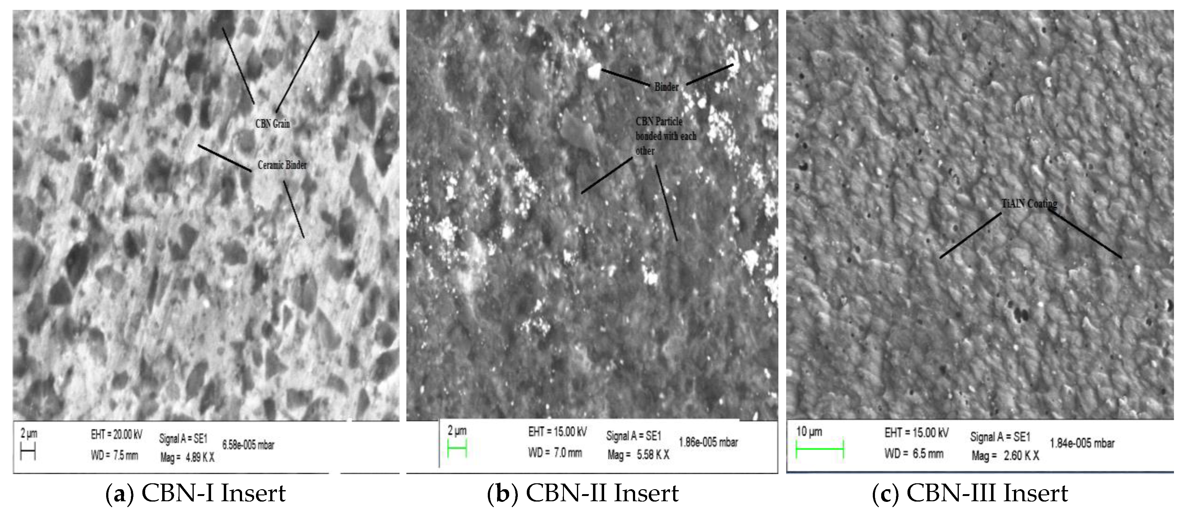
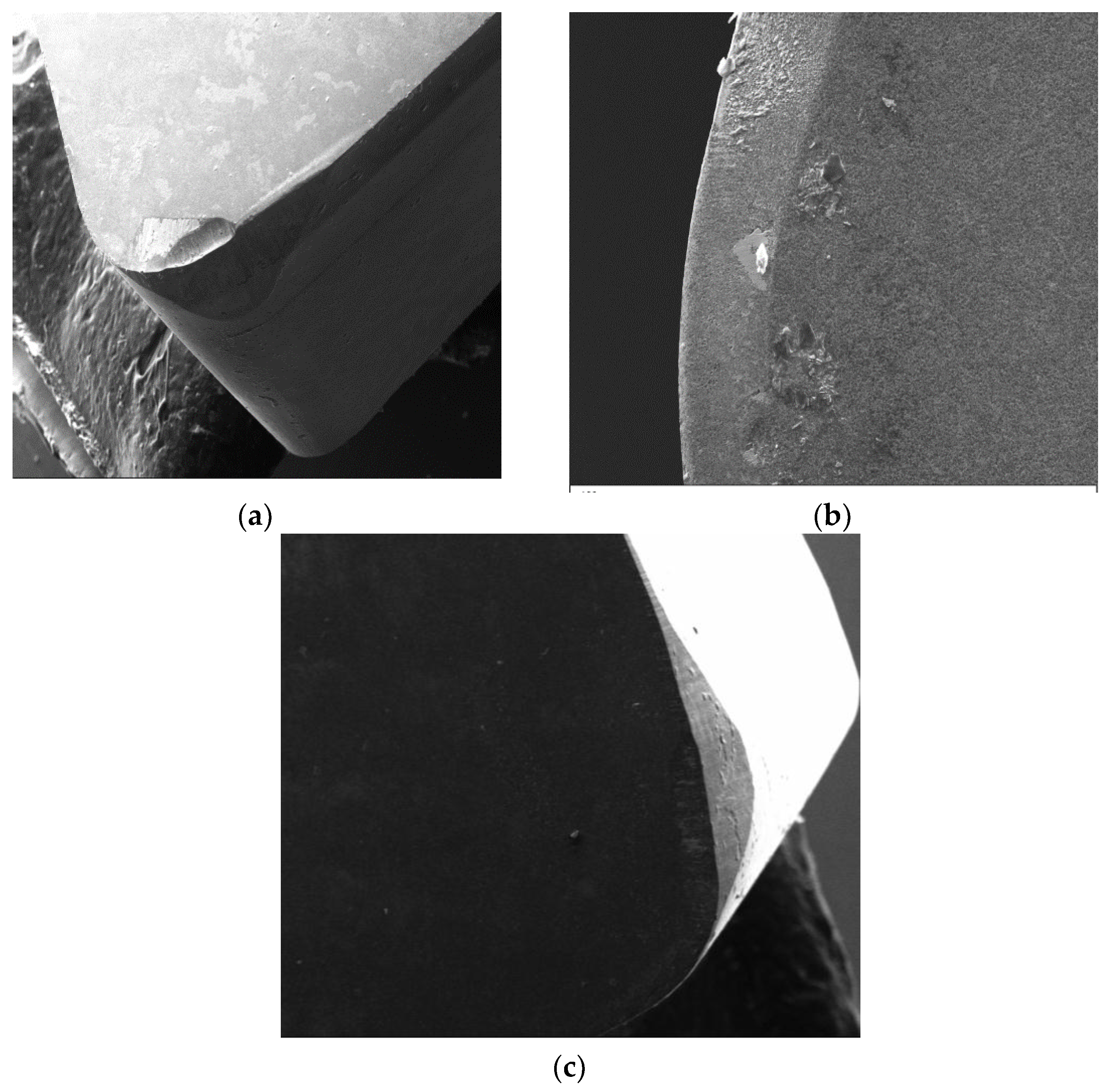
2.2. Cutting Tool
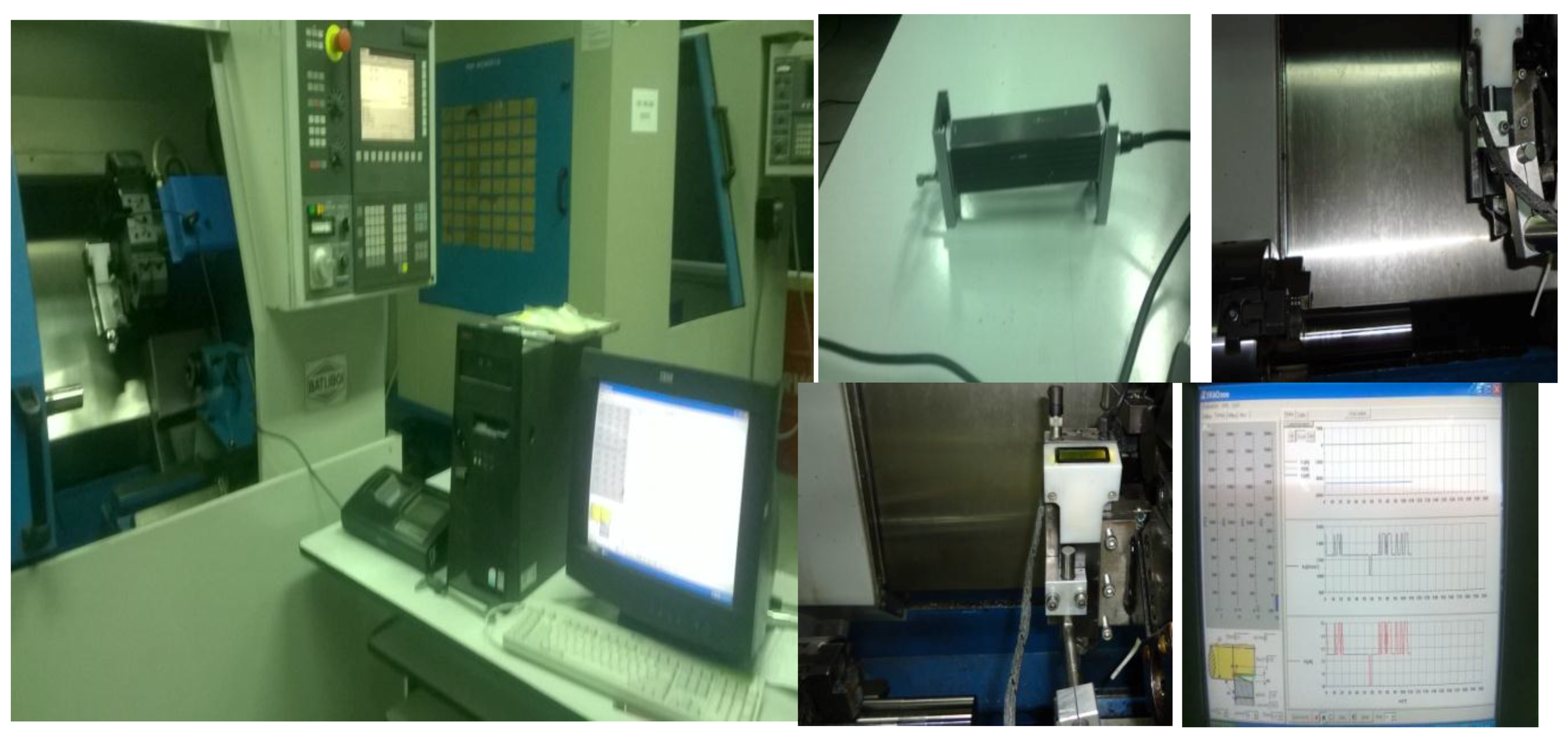
2.3. Machine Set-Up and Measurements
2.4. Design of Experiments
3. Results
3.1. Analysis for Surface Roughness (Ra)
3.1.1. Responses Surface Model for Surface Roughness (Ra)
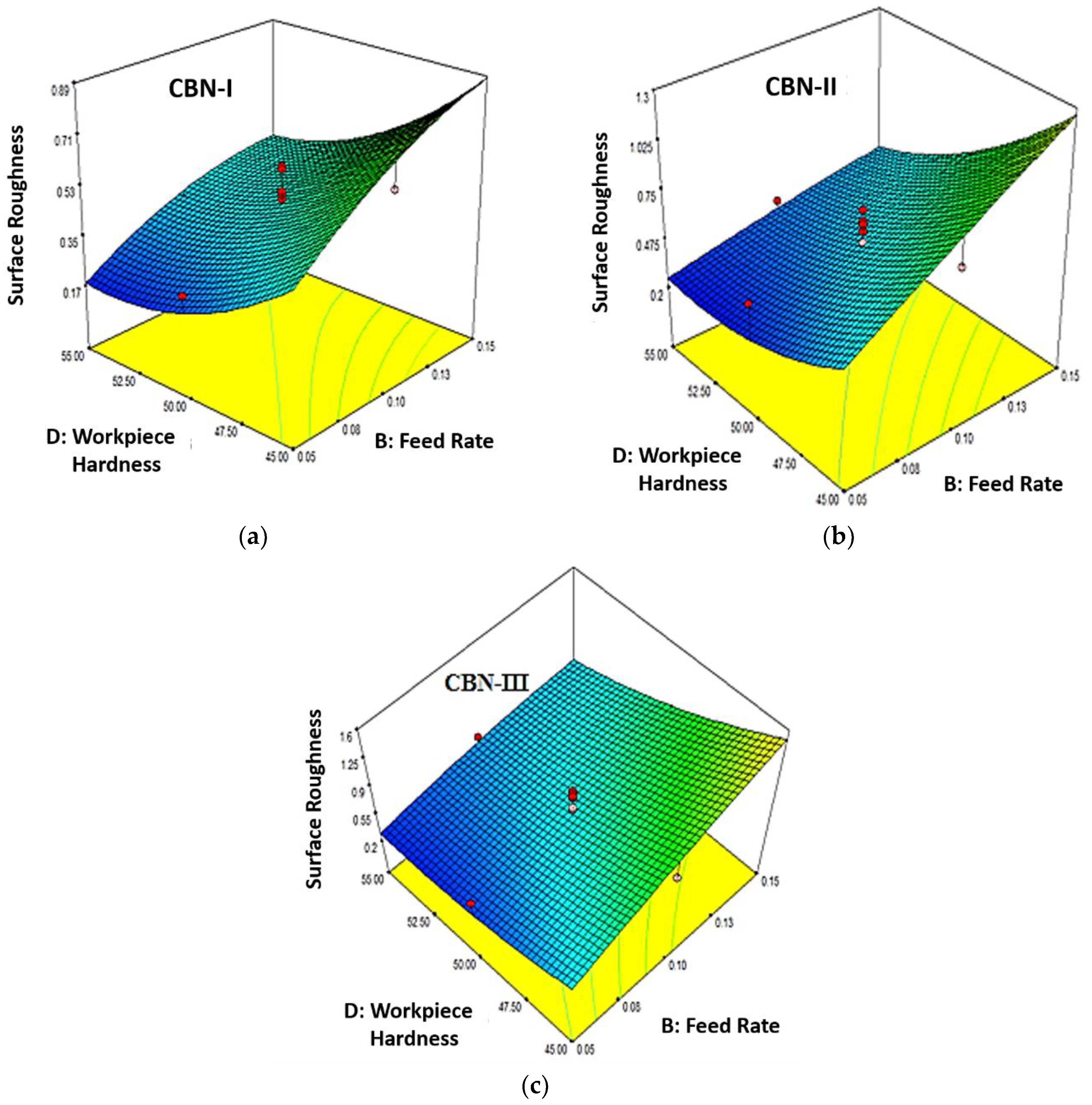
3.1.2. Parametric Influence on Surface Roughness (Ra)
3.2. Analysis for Tangential Forces (Fc)
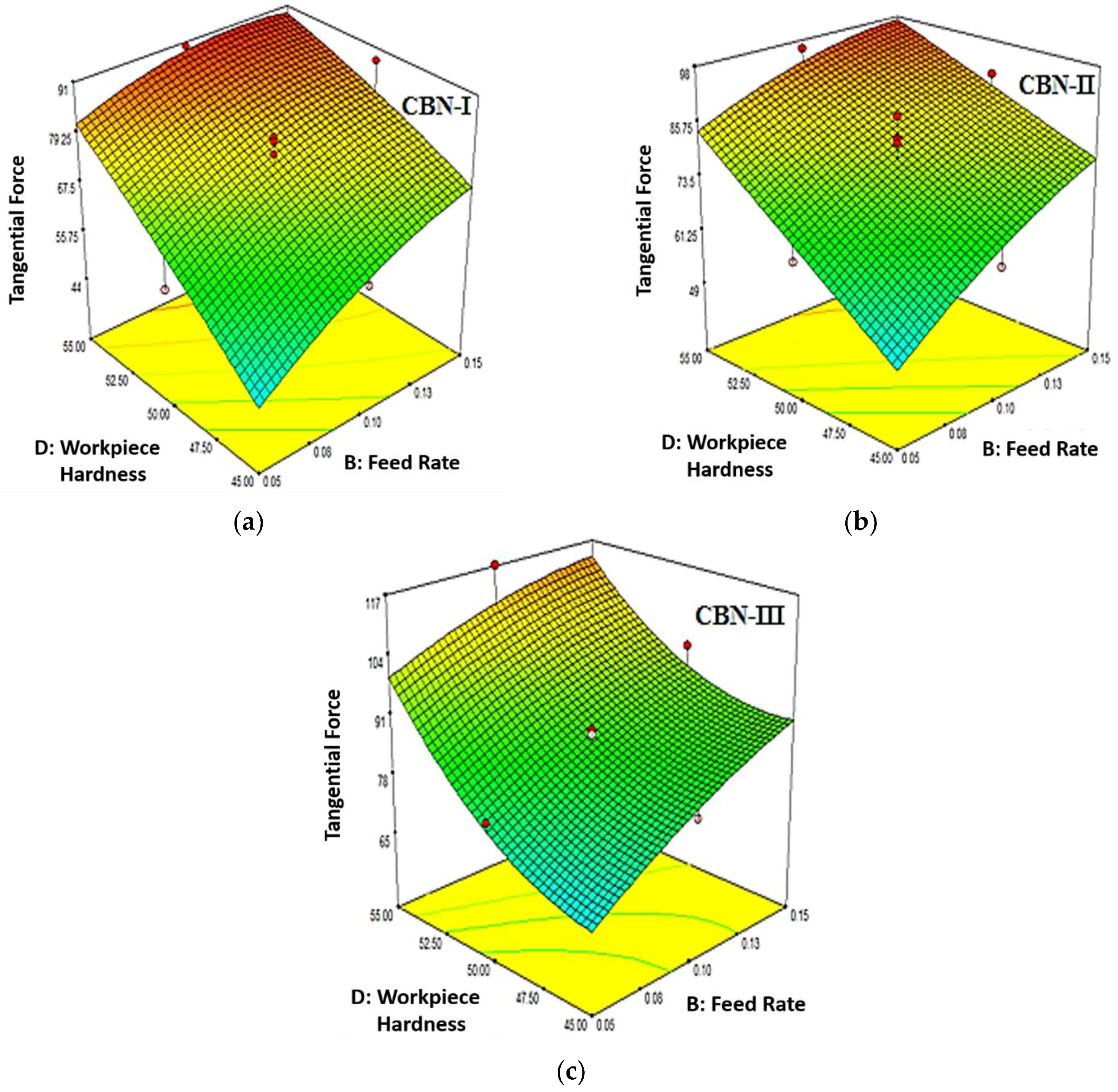
3.2.1. Response Surface Model for Tangential Force (Fc)
3.2.2. Parametric Influence on Tangential Force (Fc)
3.3. Analysis for Thrust Force (Ft)
3.3.1. Response Surface Model for Thrust Force (Ft)
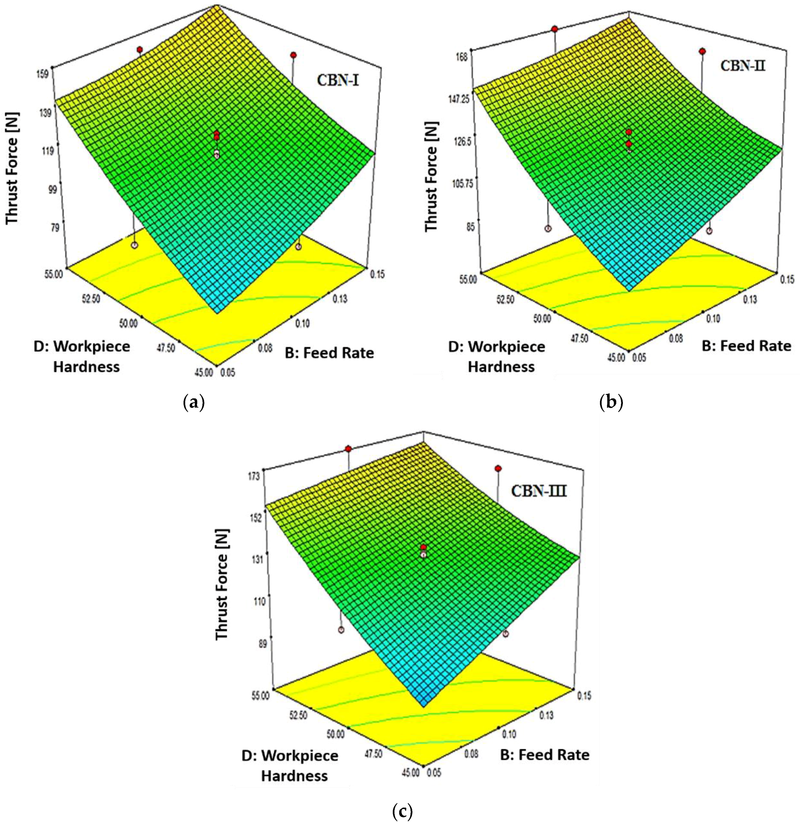
3.3.2. Parametric Influence on Thrust Force
3.4. Optimization of Cutting Conditions Using Desirability Approach
4. Conclusions
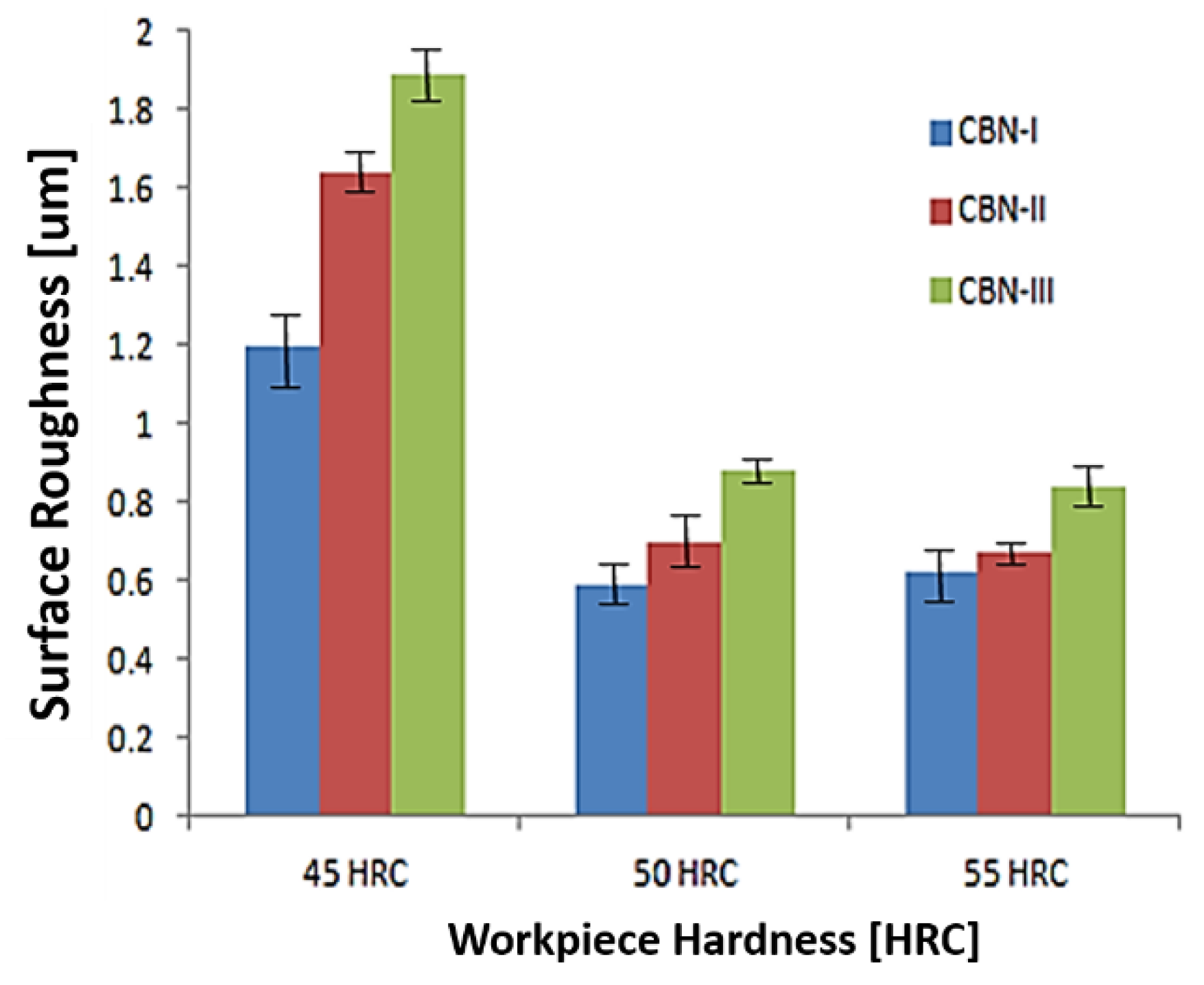
- This study demonstrated that CBN-I (BNX-10 Grade) insert is the best choice for continuous hard turning operation when compared to CBN-II (BN-600 Grade) and CBN-III (BNC-300 Grade) inserts. CBN-I generates a better surface roughness (Ra) and lower cutting forces during the hard turning of AISI H13 die tool steel in respect to CBN-II (BN-600 Grade) and CBN-III (BNC-300 Grade) inserts that correspond to workpiece hardness of 45 HRC, 50 HRC and 55 HRC, respectively. Therefore, CBN-I (BNX-10 Grade) is recommended for continuous hard turning in order to obtain a better surface roughness (Ra).
- Surface roughness (Ra) generated by CBN-I (BNX-10 Grade) insert are 26% and 36% better than CBN-II (BN-600 Grade) and CBN-III (BNC-300 Grade) inserts respectively from a workpiece having a hardness of 45 HRC. Similarly, CBN-I (BNX-10 Grade) depicts a better surface roughness (Ra) of 14% and 32% at 50 HRC and 7% and 26% at 55 HRC.
- The results revealed that the surface roughness (Ra) decreases with the increase in workpiece hardness. Better surface roughness has been achieved at the higher hardness (55 HRC) as compare to lower workpiece hardness (50 HRC and 45 HRC), which confirm the potential of hard turning with CBN tool. Also surface roughness (Ra) increases with increase in feed rate.
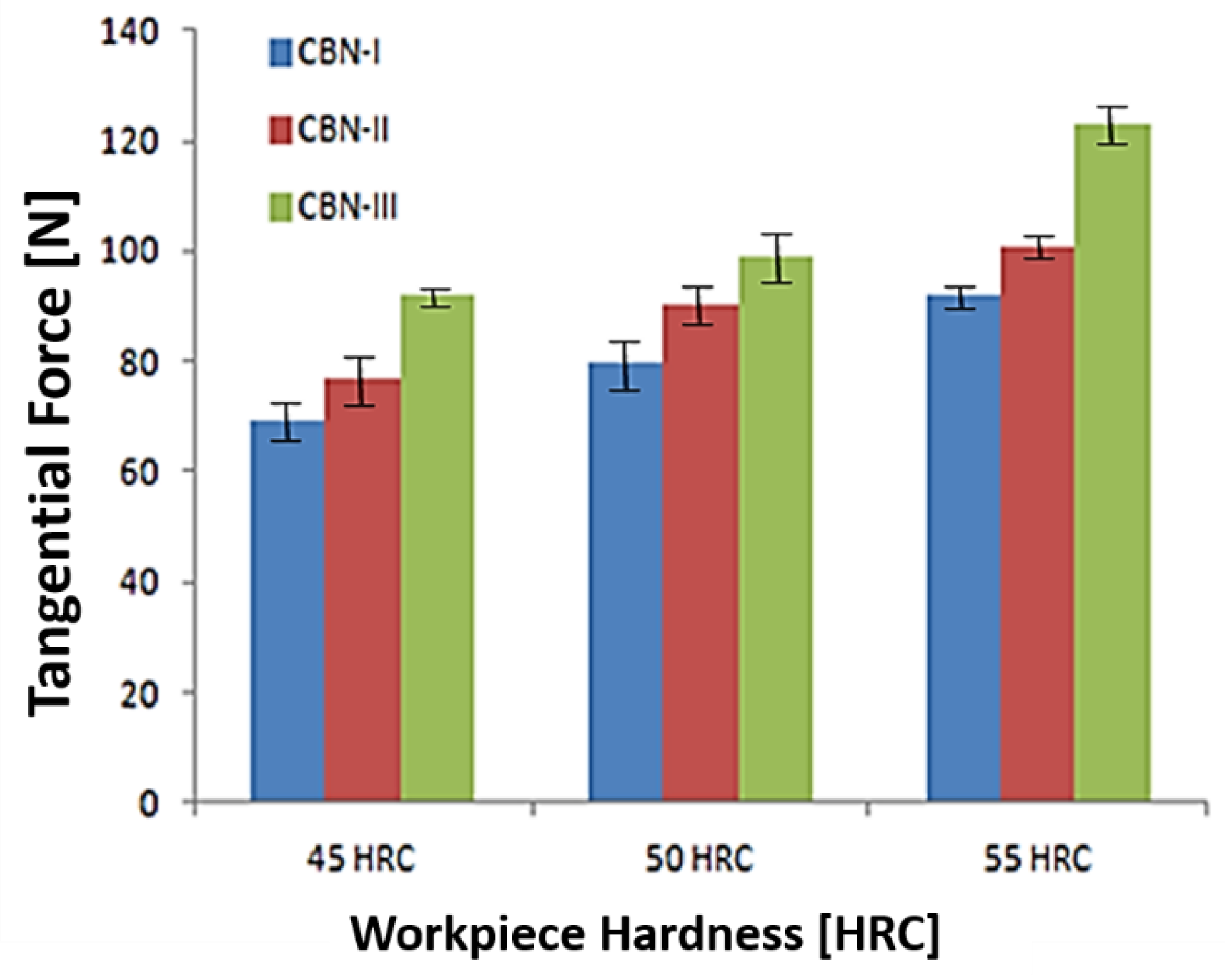
- The tangential force (Fc) is found to be maximum at higher workpiece hardness (55 HRC) with CBN-III (BNC-300 Grade) inserts, and decreases with workpiece hardness.
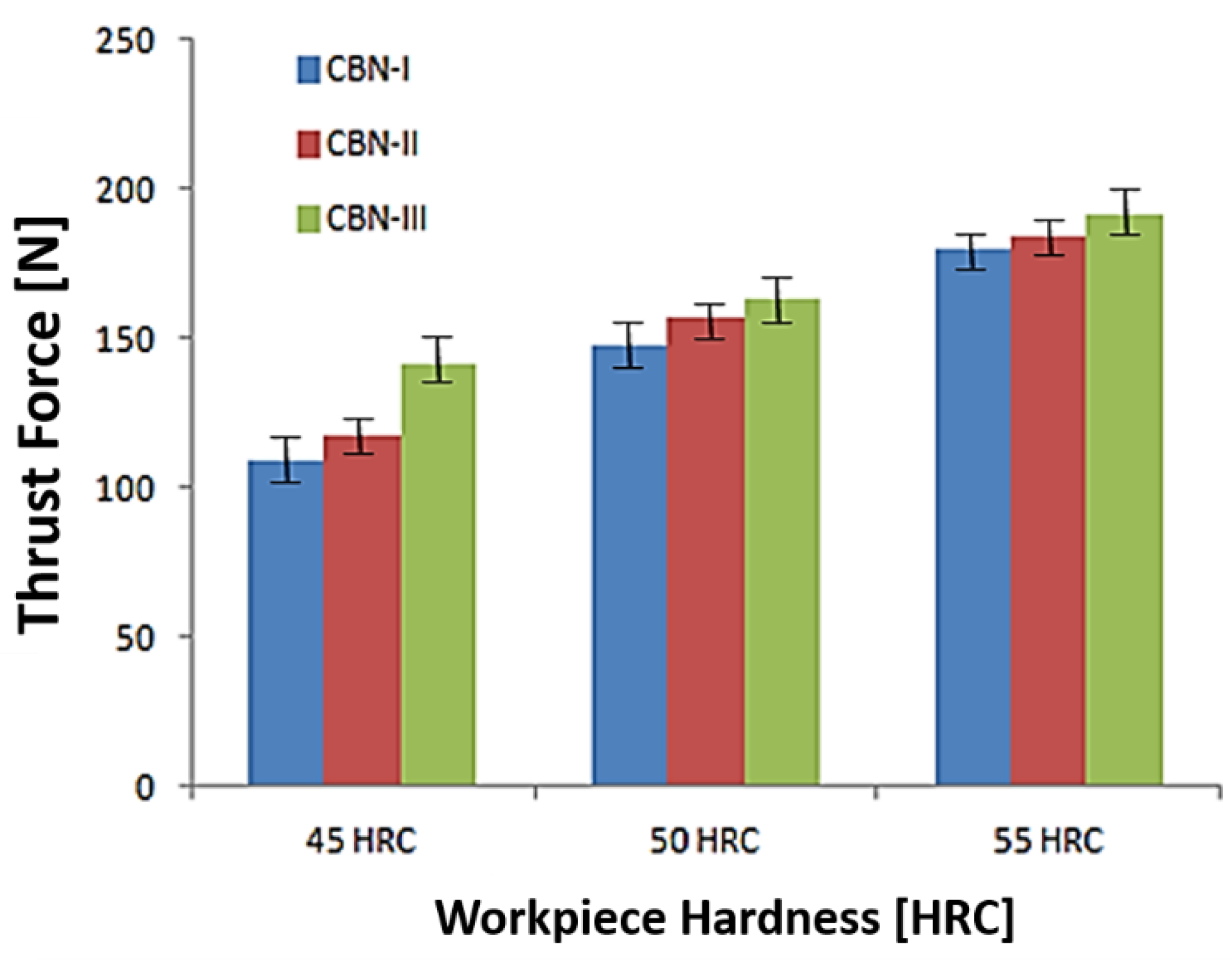
- Thrust forces (Ft) are 40–70% higher than the tangential forces and are found to be higher at the workpiece hardness of 55 HRC for each CBN inserts. It has also been noticed that CBN-III (BNC-300 Grade) insert produce the higher thrust force (Ft) during hard turning, as compared to CBN-II (BN-600 Grade) and CBN-I inserts.
- An optimum value of cutting conditions has been achieved with desirability function for CBN-I, CBN-II (BN-600 Grade) and CBN-III (BNC-300 Grade) inserts. The optimum cutting conditions for surface roughness, tangential force and thrust force corresponding to CBN-I (BNX-10 Grade) inserts are as cutting speed = 180 m/min, DOC = 0.08 mm, feed rate = 0.05 mm/rev, and workpiece hardness = 45 HRC.
Author Contributions
Funding
Conflicts of Interest
References
- Chen, T.; Li, S.; Han, B.; Liu, G. Study on cutting force and surface micro-topography of hard turning of GCr15 steel. Int. J. Adv. Manuf. Technol. 2014, 72, 1639–1645. [Google Scholar] [CrossRef]
- König, W.; Neises, A. Wear mechanisms of ultrahard, non-metallic cutting materials. Wear 1993, 162, 12–21. [Google Scholar] [CrossRef]
- Eda, H.; Kishi, K.; Hashimoto, H. Wear resistance and cutting ability of a newly developed cutting tool materials. Proc. Int. Conf. Am. Soc. Met. 1980, 15–17, 265–280. [Google Scholar]
- Bossom, P.K. Finish machining of hard ferrous workpieces. Ind. Diamond Rev. 1990, 50, 228–232. [Google Scholar]
- Bushlya, V.; Zhou, J.; Ståhl, J.E. Effect of cutting conditions on machinability of superalloy Inconel 718 during high speed turning with coated and uncoated PCBN tools. Procedia CIRP 2012, 3, 370–375. [Google Scholar] [CrossRef]
- Huang, Y.; Liang, S.Y. Cutting forces modeling considering the effect of tool thermal property—Application to CBN hard turning. Int. J. Mach. Tool. Manuf. 2003, 43, 307–315. [Google Scholar] [CrossRef]
- Singh, D.; Rao, P.V. A surface roughness prediction model for hard turning process. Int. J. Adv. Manuf. Technol. 2007, 32, 1115–1124. [Google Scholar] [CrossRef]
- Qian, L.; Hossan, M.R. Effect on cutting force in turning hardened tool steels with cubic boron nitride inserts. J. Mater. Process. Technol. 2007, 191, 274–278. [Google Scholar] [CrossRef]
- Mikołajczyk, T.; Nowicki, K.; Bustillo, A.; Pimenov, D.Y. Predicting tool life in turning operations using neural networks and image processing. Mech. Syst. Signal Process. 2018, 104, 503–513. [Google Scholar] [CrossRef]
- Mikołajczyk, T.; Nowicki, K.; Kłodowski, A.; Pimenov, D.Y. Neural network approach for automatic image analysis of cutting edge wear. Mech. Syst. Signal Process. 2017, 88, 100–110. [Google Scholar] [CrossRef]
- Nieslony, P.; Krolczyk, G.M.; Wojciechowski, S.; Chudy, R.; Zak, K.; Maruda, R.W. Surface quality and topographic inspection of variable compliance part after precise turning. Appl. Surf. Sci. 2018, 434, 91–101. [Google Scholar] [CrossRef]
- Fernández-Abia, A.I.; Barreiro, J.; Lacalle, L.L.; Martínez, S. Effect of very high cutting speeds on shearing, cutting forces and roughness in dry turning of austenitic stainless steels. Int. J. Adv. Manuf. Technol. 2011, 57, 61–71. [Google Scholar] [CrossRef]
- Mia, M.; Gupta, M.K.; Lozano, J.A.; Carou, D.; Pimenov, D.Y.; Królczyk, G.; Khan, A.M.; Dhar, N.R. Multi-objective optimization and life cycle assessment of eco-friendly cryogenic N2 assisted turning of Ti-6Al-4V. J. Clean. Prod. 2019, 210, 121–133. [Google Scholar] [CrossRef]
- Karkalos, N.E.; Galanis, N.I.; Markopoulos, A.P. Surface roughness prediction for the milling of Ti-6Al-4V ELI alloy with the use of statistical and soft computing techniques. Measurement 2016, 90, 25–35. [Google Scholar] [CrossRef]
- Maruda, R.W.; Krolczyk, G.M.; Wojciechowski, S.; Zak, K.; Habrat, W.; Nieslony, P. Effects of extreme pressure and anti-wear additives on surface topography and tool wear during MQCL turning of AISI 1045 steel. J. Mech. Sci. Technol. 2018, 32, 1585–1591. [Google Scholar] [CrossRef]
- Krolczyk, G.M.; Maruda, R.W.; Krolczyk, J.B.; Nieslony, P.; Wojciechowski, S.; Legutko, S. Parametric and nonparametric description of the surface topography in the dry and MQCL cutting conditions. Measurement 2018, 121, 225–239. [Google Scholar] [CrossRef]
- Dawson, T.G.; Kurfess, T.R. Tool Life, Wear Rates and Surfacebquality in Hard Turning; The George W. Woodruff School of Mechanical Engineering Georgia Institute of Technology: Atlanta, GA, USA, 1995. [Google Scholar]
- Ko, T.J.; Kim, H.S. Surface Integrity and Machineability in Intermittent Hard Turning. Int. J. Adv. Manuf. Technol. 2001, 18, 168–175. [Google Scholar] [CrossRef]
- Thiele, J.D.; Melkote, S.N. Effect of cutting edge geometry and workpiece hardness on surface generation in the finish hard turning of AISI 52100 steel. Int. J. Adv. Manuf. Technol. 1999, 94, 216–226. [Google Scholar] [CrossRef]
- Varadarajan, S.; Philip, P.K.; Ramamoorthy, B. Investigations on hard turning with minimal cutting fluid application (HTMF) and its comparison with dry and wet turning. Int. J. Mach. Tools Manuf. 2002, 42, 193–200. [Google Scholar] [CrossRef]
- Feng, C.X.; Wang, X. Development of empirical models for surface roughness prediction in finish turning. Int. J. Adv. Manuf. Technol. 2002, 20, 348–356. [Google Scholar]
- Choudhury, S.K.; Bartarya, G. Role of temperature and surface finish in predicting tool wear using neural network and design of experiments. Int. J. Mach. Tools Manuf. 2003, 43, 747–753. [Google Scholar] [CrossRef]
- Arumugam, S.; Sriram, G.; Rajmohan, T. Multi-Response Optimization of Epoxidation Process Parameters of Rapeseed Oil Using Response Surface Methodology (RSM)-Based Desirability Analysis. Arabian J. Sci. Eng. 2014, 39, 2277–2287. [Google Scholar] [CrossRef]
- Noordin, M.Y.; Venkatesh, V.C.; Sharif, S.; Elting, S.; Abdullah, A. Application of response surface methodology in describing the performance of coated carbide tools when turning AISI 1045 steel. J. Mater. Process. Technol. 2004, 145, 46–58. [Google Scholar] [CrossRef]
- Rajmohan, T.; Palanikumar, K. Application of the central composite design in optimization of machining parameters in drilling hybrid metal matrix composites. Measurement 2013, 46, 1470–1481. [Google Scholar] [CrossRef]
- Kohli, A.; Singh, H. Optimization of processing parameters in induction hardening using response surface methodology. Sadhana Acad. Proc. Eng. Sci. 2011, 36, 141–152. [Google Scholar] [CrossRef]
- Camposeco-Negrete, C. Optimization of cutting parameters using Response Surface Method for minimizing energy consumption and maximizing cutting quality in turning of AISI 6061 T6 aluminum. J. Clean. Prod. 2015, 91, 109–117. [Google Scholar] [CrossRef]
- Chavoshi, S.Z.; Tajdari, M. Surface roughness modelling in hard turning operation of AISI 4140 using CBN cutting tool. Int. J. Mater. Form. 2010, 3, 233–239. [Google Scholar] [CrossRef]
- Abbas, A.T.; Pimenov, D.Y.; Erdakov, I.N.; Mikolajczyk, T.; El Danaf, E.A.; Taha, M.A. Minimization of turning time for high-strength steel with a given surface roughness using the Edgeworth-Pareto optimization method. Int. J. Adv. Manuf. Technol. 2017, 93, 2375–2392. [Google Scholar] [CrossRef]
- Abbas, A.T.; Pimenov, D.Y.; Erdakov, I.N.; Taha, M.A.; Soliman, M.S.; El Rayes, M.M. ANN surface roughness optimization of AZ61 magnesium alloy finish turning: Minimum machining times at prime machining costs. Materials 2018, 11, 808. [Google Scholar] [CrossRef]
- Abbas, A.T.; Pimenov, D.Y.; Erdakov, I.N.; Taha, M.A.; El Rayes, M.M.; Soliman, M.S. Artificial intelligence monitoring of hardening methods and cutting conditions and their effects on surface roughness, performance, and finish turning costs of solid-state recycled aluminum alloy 6061 chips. Metals 2018, 8, 394. [Google Scholar] [CrossRef]
- Nayak, M.; Sehgal, R. Effect of Tool Material Properties and Cutting Conditions on Machinability of AISI D6 Steel during Hard Turning. Arabian J. Sci. Eng. 2015, 40, 1151–1164. [Google Scholar] [CrossRef]
- Aouici, H.; Yallese, M.A.; Chaoui, K.; Mabrouki, T.; Rigal, J.-F. Analysis of surface roughness and cutting force components in hard turning with CBN tool: Prediction model and cutting conditions optimization. Measurement 2012, 45, 344–353. [Google Scholar] [CrossRef]
- Garg, S.; Manna, A.; Jain, A. An Investigation on Machinability of Al/10% ZrO-Metal Matrix Composite by WEDM and Parametric Optimization Using Desirability Function Approach. Arabian J. Sci. Eng. 2014, 39, 3251–3270. [Google Scholar] [CrossRef]
- Rocha, L.C.S.; de Paiva, A.P.; Rotela Junior, P.; Balestrassi, P.P.; da Silva Campos, P.H. Robust multiple criteria decision making applied to optimization of AISI H13 hardened steel turning with PCBN wiper tool. Int. J. Adv. Manuf. Technol. 2017, 89, 2251–2268. [Google Scholar] [CrossRef]
- Rocha, L.C.S.; de Paiva, A.P.; Rotela Junior, P.; Balestrassi, P.P.; da Silva Campos, P.H.; Davim, J.P. Robust weighting applied to optimization of AISI H13 hardened-steel turning process with ceramic wiper tool: A diversity-based approach. Precis. Eng. 2017, 50, 235–247. [Google Scholar] [CrossRef]


| C | Mn | Si | Cr | Ni | Mo | V | Cu | P | S | Al | W | Fe |
|---|---|---|---|---|---|---|---|---|---|---|---|---|
| 0.35% | 0.32% | 0.87% | 5.04% | 0.12% | 1.64% | 1.05% | 0.19% | 0.01% | 0.00% | 0.006% | 0.01% | 90.31% |
| CBN Inserts Type | CBN-I | CBN-II | CBN-III |
|---|---|---|---|
| Company Make | Sumitomo | Sumitomo | Sumitomo |
| Insert Grade | BNX 10 | BN 600 | BNC 300 |
| Type | Low-CBN | High- CBN | Coated- CBN (TiAlN Coating) |
| Grain Binder | TiCN | Co-Al | TiN |
| CBN Content (%) | 40–44 | 70–90 | 60–65 |
| Hardness of Base material (HV) | 2800–3000 | 3900–4200 | |
| CBN Grain Size (μm) | 0.5–1.0 | 1.8–2 | 1.0 |
| Cutting Edge geometry | 30° × 0.1 mm (Chamfered) | 30° × 0.1 mm (Chamfered) | 25° × 0.005 mm (Chamfered) |
| Serial Number | Parameters (Unit) | Level-1 | Level-2 | Level-3 |
|---|---|---|---|---|
| 1 | Cutting Speed, A (m/min) | 120 | 150 | 180 |
| 2 | Feed Rate, B (mm/rev) | 0.05 | 0.10 | 0.15 |
| 3 | Depth of Cut, C (mm) | 0.08 | 0.13 | 0.18 |
| 4 | Workpiece Hardness, D (HRC) | 45 | 50 | 55 |
| Run | C/S (m/min) | F/R (mm/rev) | DOC (mm) | W/P Hardness (HRC) | Surface Roughness (μm) | Tangential Force (N) | Thrust Force (N) | ||||||
|---|---|---|---|---|---|---|---|---|---|---|---|---|---|
| CBN-I | CBN-II | CBN-III | CBN-I | CBN-II | CBN-III | CBN-I | CBN-II | CBN-III | |||||
| 1 | 120 | 0.15 | 0.18 | 45 | 1.2 | 1.64 | 1.89 | 69 | 77 | 90 | 104 | 117 | 131 |
| 2 | 150 | 0.1 | 0.13 | 50 | 0.47 | 0.48 | 0.64 | 76 | 81 | 83 | 113 | 110 | 121 |
| 3 | 150 | 0.1 | 0.13 | 50 | 0.5 | 0.52 | 0.66 | 79 | 81 | 87 | 114 | 114 | 127 |
| 4 | 120 | 0.1 | 0.13 | 50 | 0.57 | 0.67 | 0.83 | 79 | 84 | 89 | 129 | 147 | 159 |
| 5 | 180 | 0.05 | 0.08 | 45 | 0.37 | 0.42 | 0.51 | 26 | 31 | 44 | 51 | 58 | 68 |
| 6 | 180 | 0.05 | 0.18 | 45 | 0.53 | 0.57 | 0.63 | 47 | 51 | 73 | 77 | 91 | 101 |
| 7 | 120 | 0.15 | 0.18 | 55 | 0.62 | 0.67 | 0.71 | 92 | 101 | 123 | 180 | 184 | 191 |
| 8 | 150 | 0.1 | 0.13 | 50 | 0.49 | 0.58 | 0.78 | 80 | 82 | 88 | 112 | 119 | 121 |
| 9 | 120 | 0.05 | 0.08 | 45 | 0.46 | 0.49 | 0.71 | 32 | 37 | 46 | 57 | 62 | 72 |
| 10 | 150 | 0.1 | 0.13 | 50 | 0.49 | 0.62 | 0.8 | 72 | 77 | 82 | 116 | 116 | 131 |
| 11 | 150 | 0.05 | 0.13 | 50 | 0.29 | 0.48 | 0.51 | 56 | 63 | 77 | 90 | 97 | 109 |
| 12 | 150 | 0.1 | 0.13 | 50 | 0.58 | 0.64 | 0.84 | 80 | 87 | 82 | 124 | 123 | 132 |
| 13 | 120 | 0.05 | 0.18 | 45 | 0.68 | 0.71 | 0.83 | 49 | 56 | 67 | 89 | 94 | 98 |
| 14 | 180 | 0.15 | 0.08 | 55 | 0.4 | 0.41 | 0.49 | 71 | 74 | 89 | 109 | 114 | 123 |
| 15 | 180 | 0.05 | 0.18 | 55 | 0.19 | 0.21 | 0.29 | 87 | 84 | 101 | 148 | 154 | 167 |
| 16 | 180 | 0.1 | 0.13 | 50 | 0.24 | 0.21 | 0.32 | 69 | 67 | 78 | 103 | 97 | 117 |
| 17 | 150 | 0.1 | 0.13 | 55 | 0.34 | 0.42 | 0.53 | 90 | 96 | 117 | 151 | 168 | 173 |
| 18 | 180 | 0.05 | 0.08 | 55 | 0.14 | 0.21 | 0.23 | 61 | 62 | 67 | 100 | 109 | 119 |
| 19 | 120 | 0.05 | 0.18 | 55 | 0.29 | 0.34 | 0.48 | 90 | 89 | 109 | 167 | 172 | 179 |
| 20 | 150 | 0.1 | 0.13 | 50 | 0.59 | 0.7 | 0.88 | 71 | 73 | 82 | 126 | 129 | 135 |
| 21 | 150 | 0.1 | 0.13 | 45 | 0.64 | 0.74 | 0.88 | 59 | 62 | 78 | 89 | 96 | 107 |
| 22 | 150 | 0.1 | 0.18 | 50 | 0.47 | 0.53 | 0.67 | 78 | 82 | 96 | 103 | 137 | 151 |
| 23 | 150 | 0.15 | 0.13 | 50 | 0.38 | 0.43 | 0.59 | 88 | 90 | 99 | 148 | 157 | 163 |
| 24 | 120 | 0.15 | 0.08 | 55 | 0.53 | 0.62 | 0.84 | 77 | 84 | 99 | 114 | 127 | 134 |
| 25 | 180 | 0.15 | 0.08 | 45 | 0.77 | 1.12 | 1.4 | 55 | 58 | 70 | 96 | 99 | 102 |
| 26 | 150 | 0.1 | 0.08 | 50 | 0.37 | 0.54 | 0.69 | 63 | 69 | 82 | 99 | 96 | 104 |
| 27 | 120 | 0.15 | 0.08 | 45 | 0.96 | 1.31 | 1.71 | 61 | 67 | 76 | 94 | 102 | 114 |
| 28 | 180 | 0.15 | 0.18 | 45 | 0.87 | 1.36 | 1.51 | 66 | 81 | 92 | 109 | 111 | 141 |
| 29 | 120 | 0.05 | 0.08 | 55 | 0.22 | 0.27 | 0.34 | 64 | 72 | 84 | 107 | 119 | 132 |
| 30 | 180 | 0.15 | 0.18 | 55 | 0.47 | 0.53 | 0.61 | 87 | 99 | 104 | 167 | 171 | 181 |
| Source | Sum of Squares | Df | Mean Square | F Value | p-Value, Prob > F | Remarks |
|---|---|---|---|---|---|---|
| Model | 1.42 | 14 | 0.1 | 12.01 | <0.0001 | significant |
| A-Cutting Speed | 0.13 | 1 | 0.13 | 15.81 | 0.0012 | |
| B-Feed Rate | 0.51 | 1 | 0.51 | 60.4 | <0.0001 | |
| C-Depth of Cut | 0.067 | 1 | 0.067 | 7.96 | 0.0129 | |
| D-Workpiece Hardness | 0.6 | 1 | 0.6 | 70.78 | <0.0001 | |
| Residual | 0.13 | 15 | 8.44 × 10⁻³ | |||
| Lack of Fit | 0.11 | 10 | 0.011 | 4.3 | 0.0606 | not significant |
| Pure Error | 0.013 | 5 | 2.64 × 10⁻³ | |||
| Cor Total | 1.55 | 29 | ||||
| Std. Dev. | 0.092 | R-Squared | 0.9181 | |||
| Mean | 0.5 | Adj R-Squared | 0.8417 | |||
| C.V. % | 18.23 | Pred R-Squared | 0.717 | |||
| PRESS | 0.44 | Adeq Precision | 15.322 | |||
| Source | Sum of Squares | Df | Mean Square | F Value | p-Value, Prob > F | Remarks |
|---|---|---|---|---|---|---|
| Model | 2.98 | 14 | 0.21 | 9.64 | <0.0001 | Significant |
| A-Cutting Speed | 0.16 | 1 | 0.16 | 7.12 | 0.0176 | |
| B-Feed Rate | 1.07 | 1 | 1.07 | 48.59 | <0.0001 | |
| D-Workpiece Hardness | 1.22 | 1 | 1.22 | 55.22 | <0.0001 | |
| BD | 0.26 | 1 | 0.26 | 11.8 | 0.0037 | |
| Residual | 0.33 | 15 | 0.022 | |||
| Lack of Fit | 0.3 | 10 | 0.03 | 4.57 | 0.0537 | not significant |
| Pure Error | 0.033 | 5 | 6.52 × 10⁻³ | |||
| Cor Total | 3.31 | 29 | ||||
| Std. Dev. | 0.15 | R-Squared | 0.9 | |||
| Mean | 0.61 | Adj R-Squared | 0.8067 | |||
| C.V. % | 24.15 | Pred R-Squared | 0.6176 | |||
| PRESS | 1.26 | Adeq Precision | 12.761 | |||
| Source | Sum of Squares | Df | Mean Square | F Value | p-Value, Prob > F | Remarks |
|---|---|---|---|---|---|---|
| Model | 4.12 | 14 | 0.29 | 11.12 | <0.0001 | significant |
| A-Cutting Speed | 0.31 | 1 | 0.31 | 11.6 | 0.0039 | |
| B-Feed Rate | 1.51 | 1 | 1.51 | 57.23 | <0.0001 | |
| D-Workpiece Hardness | 1.71 | 1 | 1.71 | 64.69 | <0.0001 | |
| BD | 0.4 | 1 | 0.4 | 15 | 0.0015 | |
| Residual | 0.4 | 15 | 0.026 | |||
| Lack of Fit | 0.35 | 10 | 0.035 | 3.73 | 0.0797 | not significant |
| Pure Error | 0.047 | 5 | 9.39 × 10⁻³ | |||
| Cor Total | 4.52 | 29 | ||||
| Std. Dev. | 0.16 | R-Squared | 0.9121 | |||
| Mean | 0.76 | Adj R-Squared | 0.8302 | |||
| C.V. % | 21.4 | Pred R-Squared | 0.6671 | |||
| PRESS | 1.5 | Adeq Precision | 13.352 | |||
| Source | Sum of Squares | Df | Mean Square | F Value | p-Value, Prob > F | Remarks |
|---|---|---|---|---|---|---|
| Model | 7604.28 | 14 | 543.16 | 34.94 | <0.0001 | significant |
| A-Cutting Speed | 107.56 | 1 | 107.56 | 6.92 | 0.0189 | |
| B-Feed Rate | 1317.56 | 1 | 1317.56 | 84.75 | <0.0001 | |
| C-Depth of Cut | 1334.72 | 1 | 1334.72 | 85.86 | <0.0001 | |
| D-Workpiece Hardness | 3612.5 | 1 | 3612.5 | 232.38 | <0.0001 | |
| BC | 100 | 1 | 100 | 6.43 | 0.0228 | |
| BD | 324 | 1 | 324 | 20.84 | 0.0004 | |
| Residual | 233.18 | 15 | 15.55 | |||
| Lack of Fit | 151.85 | 10 | 15.19 | 0.93 | 0.5689 | not significant |
| Pure Error | 81.33 | 5 | 16.27 | |||
| Cor Total | 7837.47 | 29 | ||||
| Std. Dev. | 3.94 | R-Squared | 0.9702 | |||
| Mean | 69.13 | Adj R-Squared | 0.9425 | |||
| C.V. % | 5.7 | Pred R-Squared | 0.9021 | |||
| PRESS | 767.16 | Adeq Precision | 24.231 | |||
| Source | Sum of Squares | Df | Mean Square | F Value | p-Value, Prob > F | Remarks |
|---|---|---|---|---|---|---|
| Model | 7673.49 | 14 | 548.11 | 30.31 | <0.0001 | significant |
| A-Cutting Speed | 200 | 1 | 200 | 11.06 | 0.0046 | |
| B-Feed Rate | 1922 | 1 | 1922 | 106.3 | <0.0001 | |
| C-Depth of Cut | 1530.89 | 1 | 1530.89 | 84.67 | <0.0001 | |
| D-Workpiece Hardness | 3226.72 | 1 | 3226.72 | 178.46 | <0.0001 | |
| BD | 203.06 | 1 | 203.06 | 11.23 | 0.0044 | |
| Residual | 271.21 | 15 | 18.08 | |||
| Lack of Fit | 158.37 | 10 | 15.84 | 0.7 | 0.7043 | not significant |
| Pure Error | 112.83 | 5 | 22.57 | |||
| Cor Total | 7944.7 | 29 | ||||
| Std. Dev. | 4.25 | R-Squared | 0.9659 | |||
| Mean | 73.9 | Adj R-Squared | 0.934 | |||
| C.V. % | 5.75 | Pred R-Squared | 0.8843 | |||
| PRESS | 919.27 | Adeq Precision | 24.131 | |||
| Source | Sum of Squares | Df | Mean Square | F Value | p-Value, Prob > F | Remarks |
|---|---|---|---|---|---|---|
| Model | 8444.64 | 14 | 603.19 | 25.79 | <0.0001 | significant |
| A-Cutting Speed | 234.72 | 1 | 234.72 | 10.04 | 0.0064 | |
| B-Feed Rate | 1682 | 1 | 1682 | 71.92 | <0.0001 | |
| C-Depth of Cut | 2178 | 1 | 2178 | 93.12 | <0.0001 | |
| D-Workpiece Hardness | 3669.39 | 1 | 3669.39 | 156.89 | <0.0001 | |
| AD | 182.25 | 1 | 182.25 | 7.79 | 0.0137 | |
| BD | 121 | 1 | 121 | 5.17 | 0.038 | |
| CD | 9 | 1 | 9 | 0.38 | 0.5444 | |
| A2 | 121.6 | 1 | 121.6 | 5.2 | 0.0376 | |
| D2 | 132.42 | 1 | 132.42 | 5.66 | 0.031 | |
| Residual | 350.83 | 15 | 23.39 | |||
| Lack of Fit | 312.83 | 10 | 31.28 | 4.12 | 0.0659 | not significant |
| Pure Error | 38 | 5 | 7.6 | |||
| Cor Total | 8795.47 | 29 | ||||
| Std. Dev. | 4.84 | R-Squared | 0.9601 | |||
| Mean | 85.13 | Adj R-Squared | 0.9229 | |||
| C.V. % | 5.68 | Pred R-Squared | 0.8373 | |||
| PRESS | 1431.06 | Adeq Precision | 22.549 | |||
| Source | Sum of Squares | Df | Mean Square | F Value | p-Value, Prob > F | Remarks |
|---|---|---|---|---|---|---|
| Model | 24360.7 | 14 | 1740.05 | 15.06 | <0.0001 | significant |
| B-Feed Rate | 3068.06 | 1 | 3068.06 | 26.56 | 0.0001 | |
| C-Depth of Cut | 5582.72 | 1 | 5582.72 | 48.33 | <0.0001 | |
| D-Workpiece Hardness | 12640.5 | 1 | 12640.5 | 109.42 | <0.0001 | |
| CD | 1425.06 | 1 | 1425.06 | 12.34 | 0.0031 | |
| C2 | 546.06 | 1 | 546.06 | 4.73 | 0.0461 | |
| Residual | 1732.79 | 15 | 115.52 | |||
| Lack of Fit | 1553.29 | 10 | 155.33 | 4.33 | 0.0598 | not significant |
| Pure Error | 179.5 | 5 | 35.9 | |||
| Cor Total | 26093.5 | 29 | ||||
| Std. Dev. | 10.75 | R-Squared | 0.9336 | |||
| Mean | 112.87 | Adj R-Squared | 0.8716 | |||
| C.V. % | 9.52 | Pred R-Squared | 0.7013 | |||
| PRESS | 7793.4 | Adeq Precision | 16.228 | |||
| Source | Sum of Squares | Df | Mean Square | F Value | p-Value, Prob > F | Remarks |
|---|---|---|---|---|---|---|
| Model | 25271.9 | 14 | 1805.13 | 12.24 | <0.0001 | significant |
| A-Cutting Speed | 800 | 1 | 800 | 5.42 | 0.0343 | |
| B-Feed Rate | 2837.56 | 1 | 2837.56 | 19.24 | 0.0005 | |
| C-Depth of Cut | 6612.5 | 1 | 6612.5 | 44.82 | <0.0001 | |
| D-Workpiece Hardness | 13230.2 | 1 | 13230.2 | 89.68 | <0.0001 | |
| CD | 900 | 1 | 900 | 6.1 | 0.026 | |
| Residual | 2212.79 | 15 | 147.52 | |||
| Lack of Fit | 1983.29 | 10 | 198.33 | 4.32 | 0.0599 | not significant |
| Pure Error | 229.5 | 5 | 45.9 | |||
| Cor Total | 27484.7 | 29 | ||||
| Std. Dev. | 12.15 | R-Squared | 0.9195 | |||
| Mean | 119.67 | Adj R-Squared | 0.8443 | |||
| C.V. % | 10.15 | Pred R-Squared | 0.6575 | |||
| PRESS | 9412.33 | Adeq Precision | 15.253 | |||
| Source | Sum of Squares | Df | Mean Square | F Value | p-Value, Prob > F | Remarks |
|---|---|---|---|---|---|---|
| Model | 25081 | 14 | 1791.5 | 16.08 | <0.0001 | significant |
| B-Feed Rate | 3068.06 | 1 | 3068.06 | 27.53 | <0.0001 | |
| C-Depth of Cut | 7688 | 1 | 7688 | 68.98 | <0.0001 | |
| D-Workpiece Hardness | 12012.5 | 1 | 12012.5 | 107.79 | <0.0001 | |
| BD | 855.56 | 1 | 855.56 | 7.68 | 0.0143 | |
| CD | 564.06 | 1 | 564.06 | 5.06 | 0.0399 | |
| Residual | 1671.68 | 15 | 111.45 | |||
| Lack of Fit | 1498.85 | 10 | 149.88 | 4.34 | 0.0595 | not significant |
| Pure Error | 172.83 | 5 | 34.57 | |||
| Cor Total | 26752.7 | 29 | ||||
| Std. Dev. | 10.56 | R-Squared | 0.9375 | |||
| Mean | 130.1 | Adj R-Squared | 0.8792 | |||
| C.V. % | 8.11 | Pred R-Squared | 0.7474 | |||
| PRESS | 6757.2 | Adeq Precision | 17.311 | |||
| Parameters | Goal | CBN Grades | Lower Limit | Upper Limit | Lower Weight | Upper Weight | Imp |
|---|---|---|---|---|---|---|---|
| Cutting Speed (m/min) | is in range | 120 | 180 | 1 | 1 | 3 | |
| Feed Rate (mm/rev) | is in range | 0.05 | 0.15 | 1 | 1 | 3 | |
| Depth of Cut (mm) | is in range | 0.08 | 0.18 | 1 | 1 | 3 | |
| Workpiece Hardness (HRC) | is in range | 45 | 55 | 1 | 1 | 3 | |
| Surface Roughness (μm) | Minimize | CBN-I | 0.14 | 1.2 | 1 | 1 | 3 |
| CBN-II | 0.21 | 1.64 | 1 | 1 | 3 | ||
| CBN-III | 0.23 | 1.89 | 1 | 1 | 3 | ||
| Tangential Force (N) | Minimize | CBN-I | 26 | 92 | 1 | 1 | 3 |
| CBN-II | 31 | 101 | 1 | 1 | 3 | ||
| CBN-III | 44 | 123 | 1 | 1 | 3 | ||
| Thrust Force (N) | Minimize | CBN-I | 51 | 180 | 1 | 1 | 3 |
| CBN-II | 58 | 184 | 1 | 1 | 3 | ||
| CBN-III | 68 | 191 | 1 | 1 | 3 |
| Inserts | Cutting Speed (m/min) | Feed Rate (mm/rev) | Depth of Cut (mm) | Workpiece Hardness (HRC) | Surface Roughness (μm) | Tangential Force (Fc) (N) | Thrust Force (Ft) (N) | Desirability |
|---|---|---|---|---|---|---|---|---|
| CBN-I | 180 | 0.05 | 0.08 | 45.27 | 0.34293 | 26.3473 | 54.0157 | 0.923 |
| CBN-II | 180 | 0.05 | 0.08 | 45.6 | 0.37019 | 31.0196 | 57.8928 | 0.961 |
| CBN-III | 180 | 0.05 | 0.08 | 45.98 | 0.41452 | 44.2859 | 67.999 | 0.96 |
© 2019 by the authors. Licensee MDPI, Basel, Switzerland. This article is an open access article distributed under the terms and conditions of the Creative Commons Attribution (CC BY) license (http://creativecommons.org/licenses/by/4.0/).
Share and Cite
Kumar, P.; Chauhan, S.R.; Pruncu, C.I.; Gupta, M.K.; Pimenov, D.Y.; Mia, M.; Gill, H.S. Influence of Different Grades of CBN Inserts on Cutting Force and Surface Roughness of AISI H13 Die Tool Steel during Hard Turning Operation. Materials 2019, 12, 177. https://doi.org/10.3390/ma12010177
Kumar P, Chauhan SR, Pruncu CI, Gupta MK, Pimenov DY, Mia M, Gill HS. Influence of Different Grades of CBN Inserts on Cutting Force and Surface Roughness of AISI H13 Die Tool Steel during Hard Turning Operation. Materials. 2019; 12(1):177. https://doi.org/10.3390/ma12010177
Chicago/Turabian StyleKumar, Pardeep, Sant Ram Chauhan, Catalin Iulian Pruncu, Munish Kumar Gupta, Danil Yurievich Pimenov, Mozammel Mia, and Harjot Singh Gill. 2019. "Influence of Different Grades of CBN Inserts on Cutting Force and Surface Roughness of AISI H13 Die Tool Steel during Hard Turning Operation" Materials 12, no. 1: 177. https://doi.org/10.3390/ma12010177
APA StyleKumar, P., Chauhan, S. R., Pruncu, C. I., Gupta, M. K., Pimenov, D. Y., Mia, M., & Gill, H. S. (2019). Influence of Different Grades of CBN Inserts on Cutting Force and Surface Roughness of AISI H13 Die Tool Steel during Hard Turning Operation. Materials, 12(1), 177. https://doi.org/10.3390/ma12010177