Microstructure and Tribological Properties of Laser Forming Repaired 34CrNiMo6 Steel


Abstract
:1. Introduction
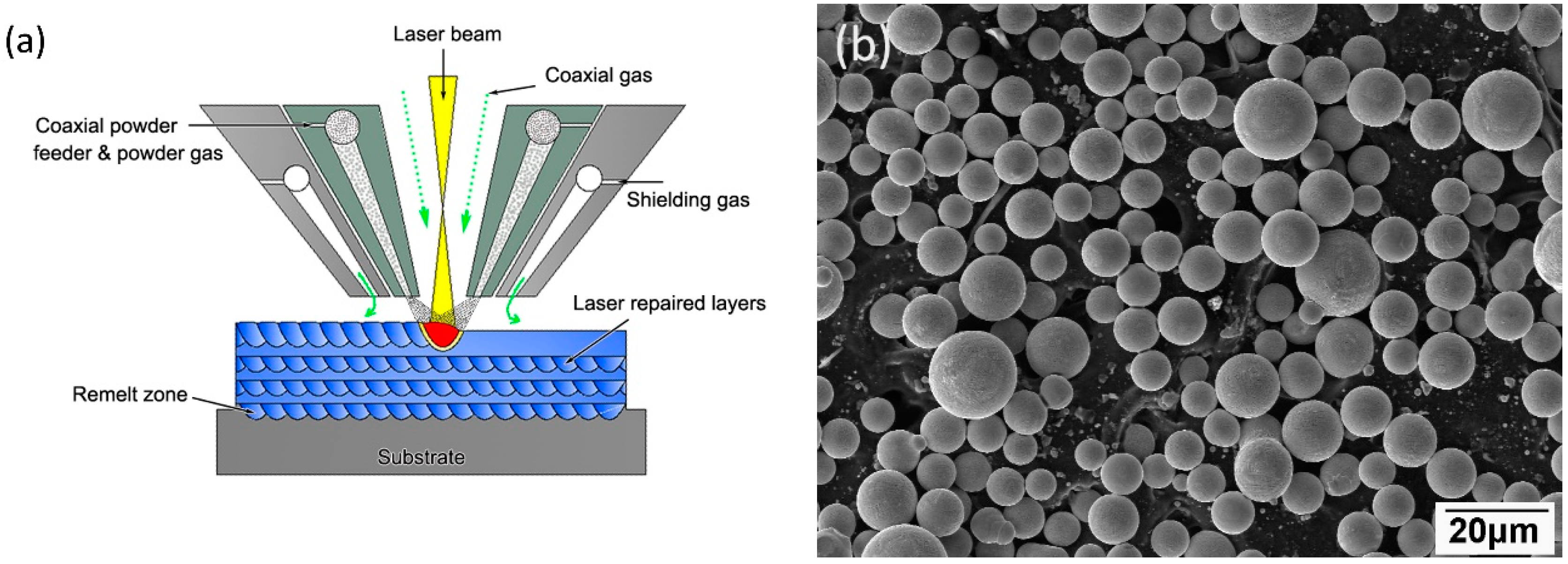
2. Experiment
3. Results and Discussion
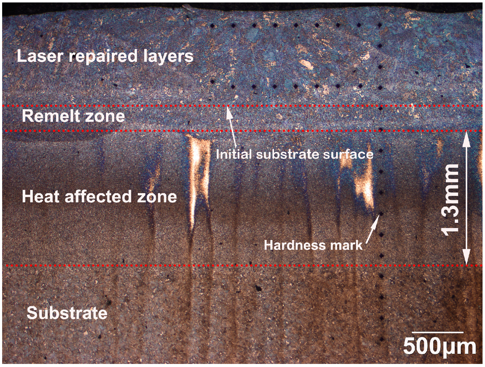
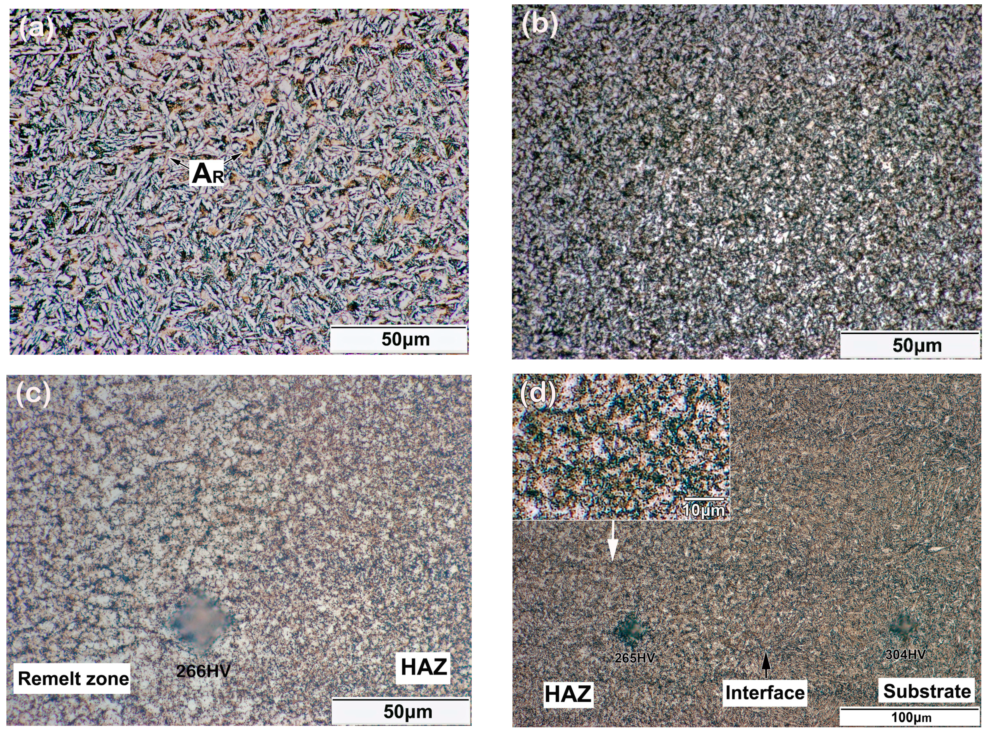
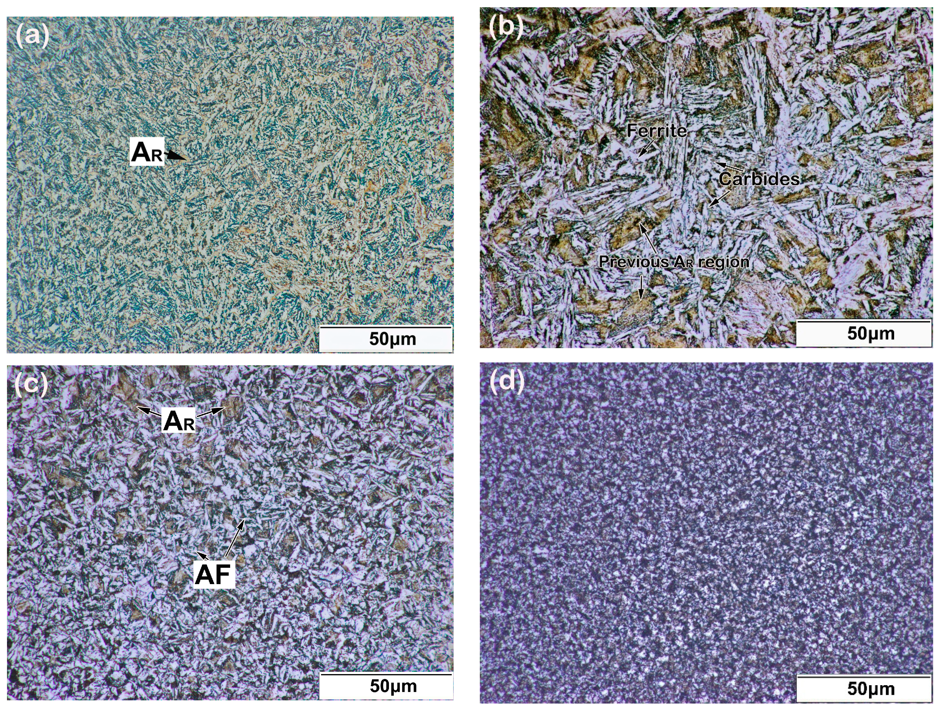
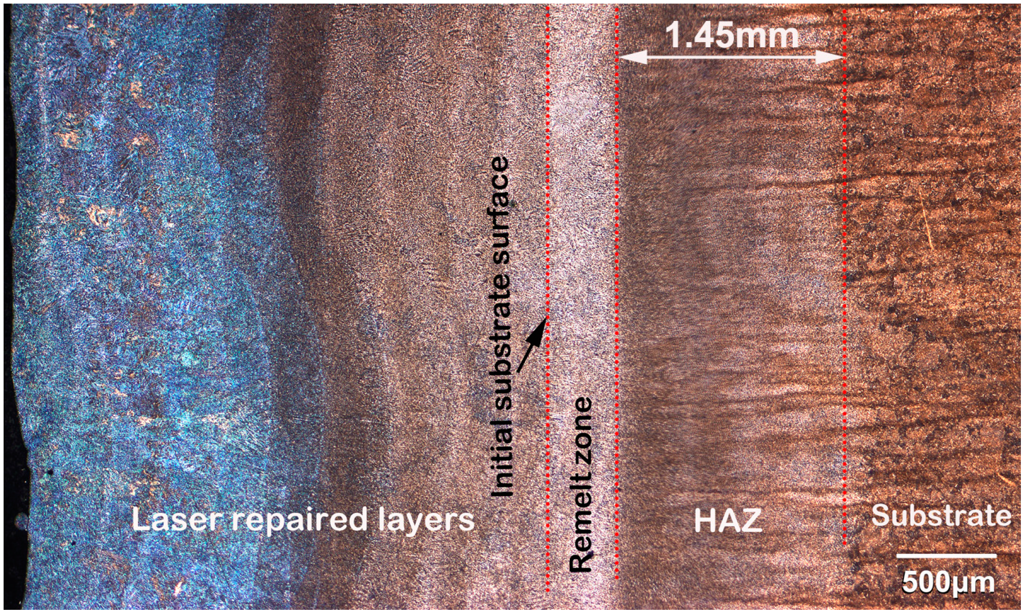
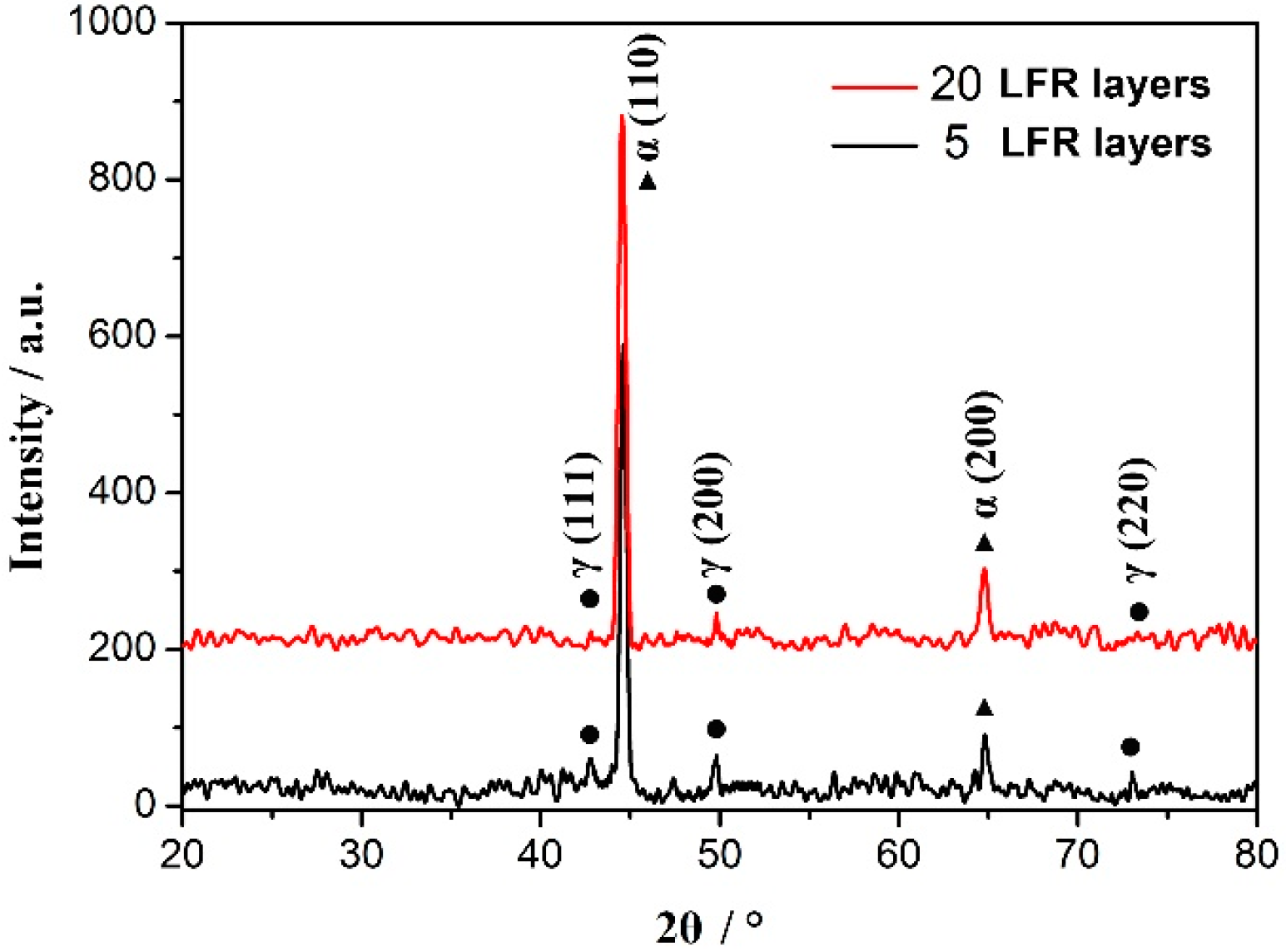
3.1. Microstructure Evolution
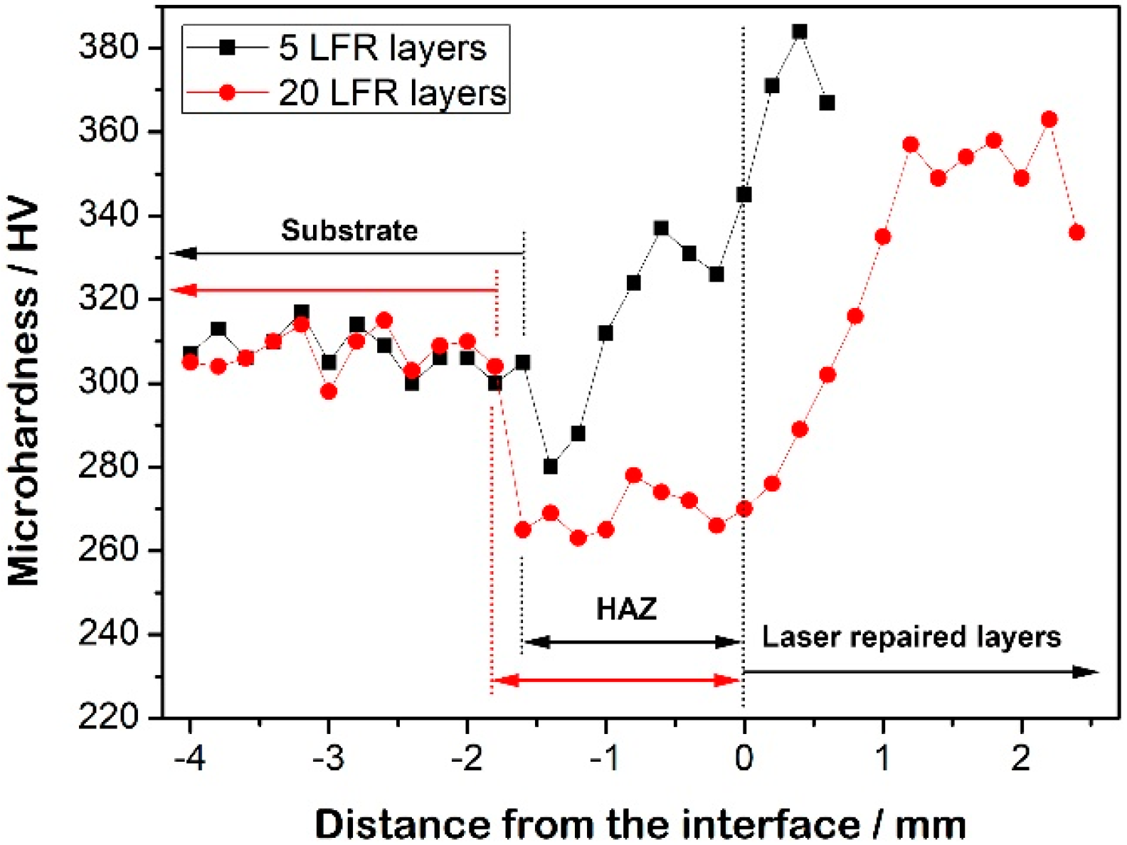
3.2. Microhardness
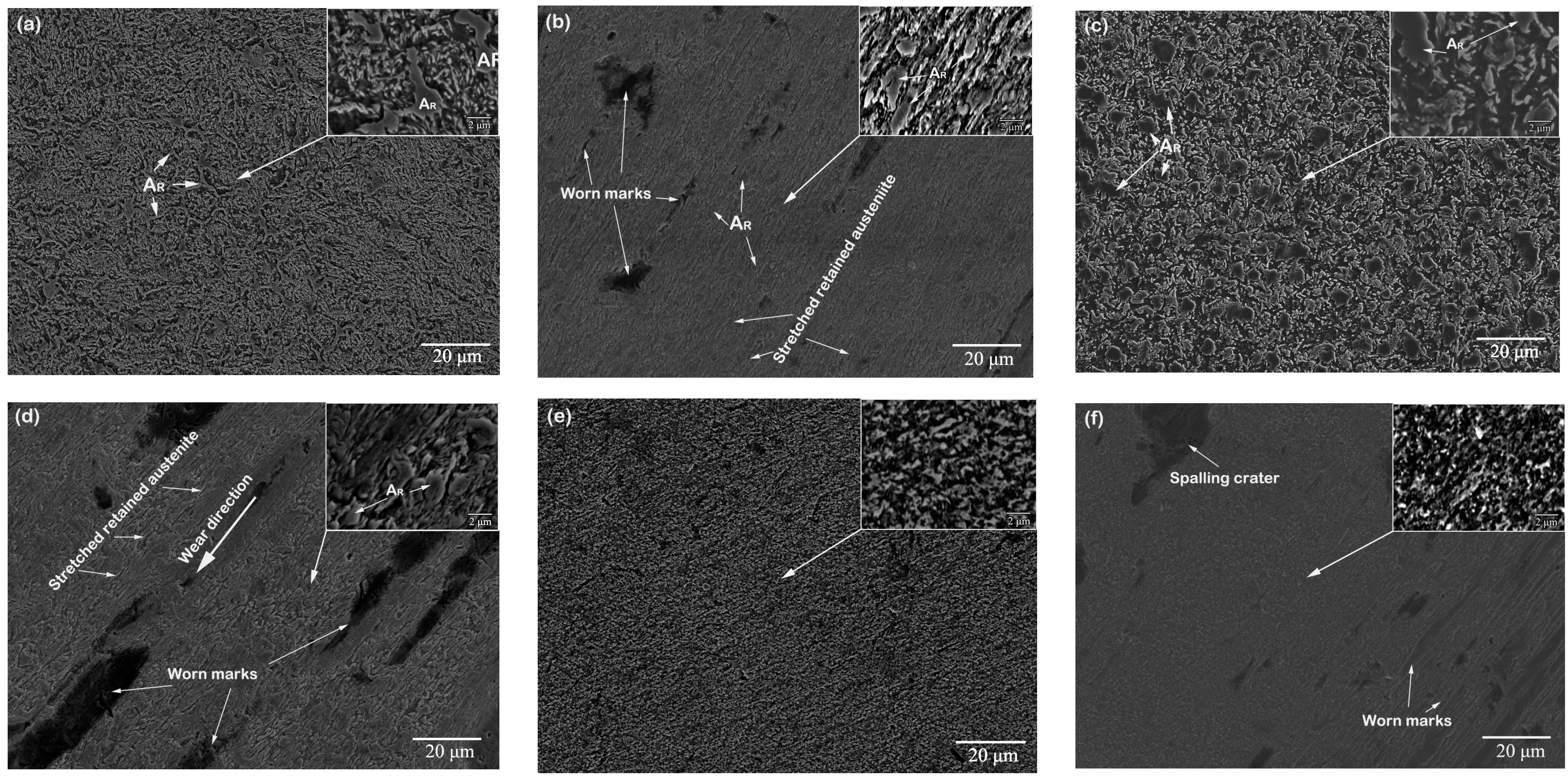
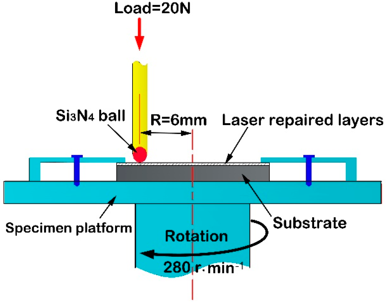
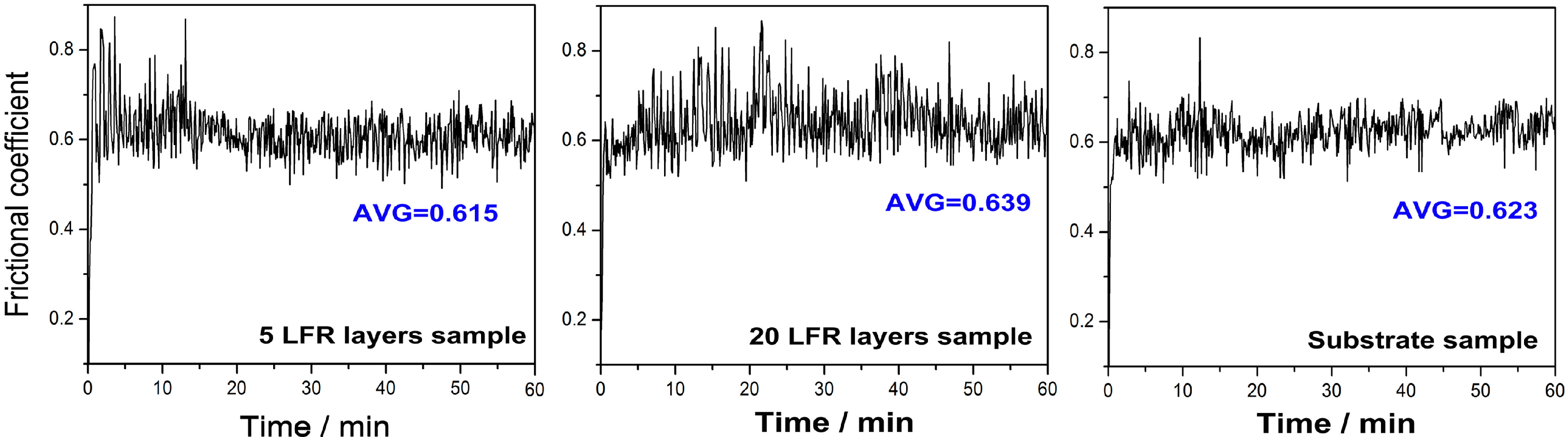
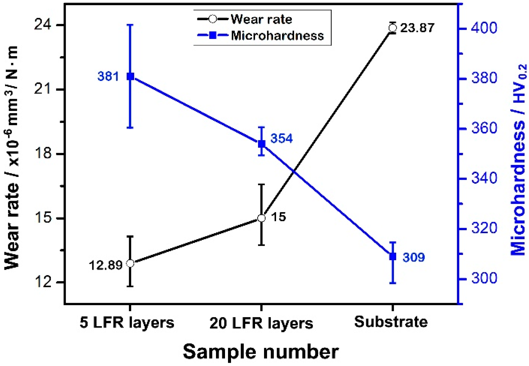
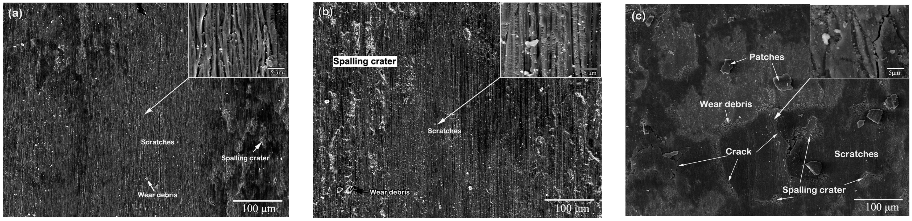
3.3. Tribological Properties
4. Conclusions
Author Contributions
Funding
Conflicts of Interest
References
- Maropoulos, S.; Ridley, N.; Karagiannis, S. Structural variations in heat treated low alloy steel forgings. Mater. Sci. Eng. A 2004, 380, 79–92. [Google Scholar] [CrossRef]
- Branco, R.; Costa, J.D.; Antunes, F.V. Low-cycle fatigue behavior of 34CrNiMo6 high strength steel. Theor. Appl. Fract. Mech. 2012, 58, 28–34. [Google Scholar] [CrossRef]
- Kuduzović, A.; Poletti, M.C.; Sommitsch, C.; Domankova, M.; Mitsche, S. Investigations into the delayed fracture susceptibility of 34CrNiMo6 steel, and the opportunities for its application in ultra-high-strength bolts and fasteners. Mater. Sci. Eng. A 2014, 590, 66–73. [Google Scholar] [CrossRef]
- Choe, H.-B.; Lee, H.-S.; Shin, J.-H. Experimental study on the electrochemical anti-corrosion properties of steel structures applying the arc thermal metal spraying method. Materials 2014, 7, 7722–7736. [Google Scholar] [CrossRef] [PubMed]
- Campbell, J.E.; Kalfhaus, T.; Vassen, R.; Thompson, R.P.; Dean, J.; Clyne, T.W. Mechanical properties of sprayed overlayers on superalloy substrates, obtained via indentation testing. Acta Mater. 2018, 154, 237–245. [Google Scholar] [CrossRef]
- Wang, X.Y.; Wang, J.H.; Gao, Z.M.; Xia, D.H.; Hu, W.B. Fabrication of graded surfacing layer for the repair of failed H13 mandrel using submerged arc welding technology. J. Mater. Process. Technol. 2018, 262, 182–188. [Google Scholar] [CrossRef]
- Chen, J.Y.; Conlon, K.; Xue, L.; Rogge, R. Experimental study of residual stresses in laser clad AISI P20 tool steel on pre-hardened wrought P20 substrate. Mater. Sci. Eng. A 2010, 527, 7265–7273. [Google Scholar] [CrossRef]
- Sun, G.F.; Yao, S.; Wang, Z.D.; Shen, X.T.; Yan, Y.; Zhou, R.; Ni, Z.H. Microstructure and mechanical properties of HSLA-100 steel repaired by laser metal deposition. Surf. Coat. Technol. 2018, 351, 198–211. [Google Scholar] [CrossRef]
- Li, Y.M.; Yang, H.O.; Lin, X.; Huang, W.D.; Li, J.G.; Zhou, Y.H. The influences of processing parameters on forming characterizations during laser rapid forming. Mater. Sci. Eng. A 2003, 360, 18–25. [Google Scholar] [CrossRef]
- Li, Q.G.; Lin, X.; Liu, F.G.; Liu, F.C.; Huang, W.D. Microstructural characteristics and mechanical properties of laser solid formed K465 superalloy. Mater. Sci. Eng. A 2017, 700, 649–655. [Google Scholar] [CrossRef]
- Attar, H.; Ehtemam-Haghighi, S.; Kent, D.; Wu, X.H.; Dargusch, M.S. Comparative study of commercially pure titanium produced by laser engineered net shaping, selective laser melting and casting processes. Mater. Sci. Eng. A 2017, 705, 385–393. [Google Scholar] [CrossRef]
- Attar, H.; Ehtemam-Haghighi, S.; Kent, D.; Dargusch, M.S. Recent developments and opportunities in additive manufacturing of titanium–based matrix composites: A review. Int. J Mach. Tools Manuf. 2018, 133, 85–102. [Google Scholar] [CrossRef]
- Tucker, T.R.; Clauer, A.H.; Wright, I.G.; Stropki, J.R. Laser-processed composite metal cladding for slurry erosion resistance. Thin Solid Films 1984, 118, 73–84. [Google Scholar] [CrossRef]
- Cooper, K.P.; Ayers, J.D. Laser melt-particle injection processing. Surf. Eng. 1985, 1, 263–272. [Google Scholar] [CrossRef]
- Wang, H.Y.; Zhao, Q.Z.; Wang, H.; Cui, W.L.; Yuan, X.M. Micromechanism characteristics of modified Al-Si coating by laser melt injection CeO2 nano-particles. Surf. Coat. Technol. 2017, 319, 88–94. [Google Scholar] [CrossRef]
- Wang, L.; Yao, J.H.; Yu, Y.; Zhang, Q.L.; Sun, Z.; Liu, R. Influence of electric- magnetic compound field on the WC particles distribution in laser melt injection. Surf. Coat. Technol. 2017, 315, 32–43. [Google Scholar] [CrossRef]
- Chen, H.Y.; Gu, D.D.; Dai, D.H.; Ma, C.L.; Xia, M.J. Microstructure and composition homogeneity, tensile property, and underlying thermal physical mechanism of selective laser melting tool steel parts. Mater. Sci. Eng. A 2017, 682, 279–289. [Google Scholar] [CrossRef]
- Bhattacharya, S.; Dinda, G.P.; Dasgupta, A.K.; Mazumder, J. Microstructural evolution of AISI 4340 steel during direct metal deposition process. Mater. Sci. Eng. A 2011, 528, 2309–2318. [Google Scholar] [CrossRef]
- Sun, G.F.; Bhattacharya, S.; Dinda, G.P.; Dasgupta, A.K.; Mazumder, J. Influence of processing parameters on lattice parameters in laser deposited tool alloy steel. Mater. Sci. Eng. A 2011, 528, 5141–5145. [Google Scholar] [CrossRef]
- Sun, G.F.; Zhou, R.; Lu, J.Z.; Mazumder, J. Evaluation of defect density, microstructure, residual stress, elastic modulus, hardness and strength of laser-deposited AISI 4340 steel. Acta Mater. 2015, 84, 172–189. [Google Scholar] [CrossRef]
- Abd El-Azim, M.E.; Ghoneim, M.M.; Nasreldin, A.M.; Soliman, S. Effect of various heat treatments on microstructure and mechanical properties of 34CrNiMo6 steel. Z. Metallkd. 1997, 88, 502–507. [Google Scholar]
- Chunping, H.; Xin, L.; Fencheng, L.; Jun, C.; Fenggang, L.; Weidong, H. Effects of cooling condition on microstructure and mechanical properties in laser rapid forming of 34CrNiMo6 thin-wall component. Int. J. Adv. Manuf. Technol. 2016, 82, 1269–1279. [Google Scholar] [CrossRef]
- Kim, H.; Liu, Z.C.; Cong, W.L.; Zhang, H.C. Tensile fracture behavior and failure mechanism of additively-manufactured AISI 4140 low alloy steel by laser engineered net shaping. Materials 2017, 10, 1283. [Google Scholar] [CrossRef] [PubMed]
- Hitzler, L.; Hirsch, J.; Heine, B.; Merkel, M.; Hall, W.; öchsner, A. On the anisotropic mechanical properties of selective laser-melted stainless steel. Materials 2017, 10, 1136. [Google Scholar] [CrossRef] [PubMed]
- Liu, F.G.; Lin, X.; Song, K.; Song, M.H.; Han, Y.F.; Huang, W.D. Microstructure and mechanical properties of laser forming repaired 300M steel. Acta Metall. Sin. 2017, 53, 325–334. [Google Scholar]
- Lin, X.; Cao, Y.Q.; Wu, X.Y.; Yang, H.O.; Chen, J.; Huang, W.D. Microstructure and mechanical properties of laser forming repaired 17-4PH stainless steel. Mater. Sci. Eng. A 2012, 553, 80–88. [Google Scholar] [CrossRef]
- Sun, S.D.; Liu, Q.C.; Brandt, M.; Luzin, V.; Cottam, R.; Janardhana, M.; Clark, G. Effect of laser clad repair on the fatigue behaviour of ultra-high strength AISI 4340 steel. Mater. Sci. Eng. A 2014, 606, 46–57. [Google Scholar] [CrossRef]
- Datsko, J.; Hartwig, L.; McClory, B. On the tensile strength and hardness relation for metals. J. Mater. Eng. Perform. 2001, 10, 718–722. [Google Scholar] [CrossRef]
- Sandomirskii, S.G. Estimation of the ultimate tensile strength of steel from its HB and HV hardness numbers and coercive force. Russ. Metall. (Metally) 2017, 11, 989–993. [Google Scholar] [CrossRef]
- Zhang, P.; Li, S.X.; Zhang, Z.F. General relationship between strength and hardness. Mater. Sci. Eng. A 2011, 529, 62–73. [Google Scholar] [CrossRef]
- Gasko, M.; Rosenberg, G. Correlation between hardness and tensile properties in ultra-high strength dual phase steels—Short communication. Mater. Eng. 2011, 18, 155–159. [Google Scholar]
- Zhang, P.; Fan, H.; Zhang, B.Q. Toughness research of 34CrNiMo6 at low temperature. Dongfang Electr. Rev. 2013, 27, 38–43. [Google Scholar]
- Zhang, J.; Kong, D.J. Effect of laser remelting on friction-wear behaviors of cold sprayed Al coatings in 3.5% NaCl solution. Materials 2018, 11, 283. [Google Scholar] [CrossRef] [PubMed]
- Fang, L.Y.; Yan, H.; Yao, Y.S.; Zhang, P.L.; Cao, Q.S.; Qin, Y. Reactive fabrication and effect of NbC on microstructure and tribological properties of CrS Co-based self-lubricating coatings by laser cladding. Materials 2018, 11, 44. [Google Scholar] [CrossRef] [PubMed]
- Lockwood, F.E. Friction, lubrication and wear technology. In ASM Handbook, 10th ed.; ASM International: Materials Park, OH, USA, 1992; Volume 18, pp. 320–448. [Google Scholar]
- Khrushchov, M.M.; Babichev, M.A. An investigation of the wear of metals and alloys by rubbing on an adhesive surface. ASME Friction Wear Mach. 1958, 12, 1–13. [Google Scholar]
- Ehtemam-Haghighi, S.; Cao, G.H.; Zhang, L.C. Nanoindentation study of mechanical properties of Ti based alloys with Fe and Ta additions. J. Alloy Compd. 2017, 692, 892–897. [Google Scholar] [CrossRef]
- Ehtemam-Haghighi, S.; Prashanth, K.G.; Attar, H.; Chaubey, A.K.; Cao, G.H.; Zhang, L.C. Evaluation of mechanical and wear properties of Ti-xNb-7Fe alloys designed for biomedical applications. Mater. Des. 2016, 111, 592–599. [Google Scholar] [CrossRef]
- Hu, F.; Wu, K.M.; Hodgson, P.D. Effect of retained austenite on wear resistance of nanostructured dual phase steels. Mater. Sci. Technol. 2016, 32, 40–48. [Google Scholar] [CrossRef]


| Element | Content (wt %) |
|---|---|
| C | 0.30–0.38 |
| Cr | 1.3–1.7 |
| Ni | 1.3–1.7 |
| Mo | 0.15–0.30 |
| Mn | 0.50–0.80 |
| Si | 0.20–0.40 |
| Fe | Balance |
| Laser Powder (W) | Spot Diameter (mm) | Increase in Axis-Z (mm) | Overlap (%) | Scanning Speed (mm·min−1) | Powder Feeding Rate (g·min−1) |
|---|---|---|---|---|---|
| 2800 | 2.5 | 0.2 | 45 | 600 | 10–15 |
© 2018 by the authors. Licensee MDPI, Basel, Switzerland. This article is an open access article distributed under the terms and conditions of the Creative Commons Attribution (CC BY) license (http://creativecommons.org/licenses/by/4.0/).
Share and Cite
Huang, C.; Lin, X.; Yang, H.; Liu, F.; Huang, W. Microstructure and Tribological Properties of Laser Forming Repaired 34CrNiMo6 Steel. Materials 2018, 11, 1722. https://doi.org/10.3390/ma11091722
Huang C, Lin X, Yang H, Liu F, Huang W. Microstructure and Tribological Properties of Laser Forming Repaired 34CrNiMo6 Steel. Materials. 2018; 11(9):1722. https://doi.org/10.3390/ma11091722
Chicago/Turabian StyleHuang, Chunping, Xin Lin, Haiou Yang, Fencheng Liu, and Weidong Huang. 2018. "Microstructure and Tribological Properties of Laser Forming Repaired 34CrNiMo6 Steel" Materials 11, no. 9: 1722. https://doi.org/10.3390/ma11091722
APA StyleHuang, C., Lin, X., Yang, H., Liu, F., & Huang, W. (2018). Microstructure and Tribological Properties of Laser Forming Repaired 34CrNiMo6 Steel. Materials, 11(9), 1722. https://doi.org/10.3390/ma11091722