Femtosecond Laser Texturing of Surfaces for Tribological Applications


Abstract
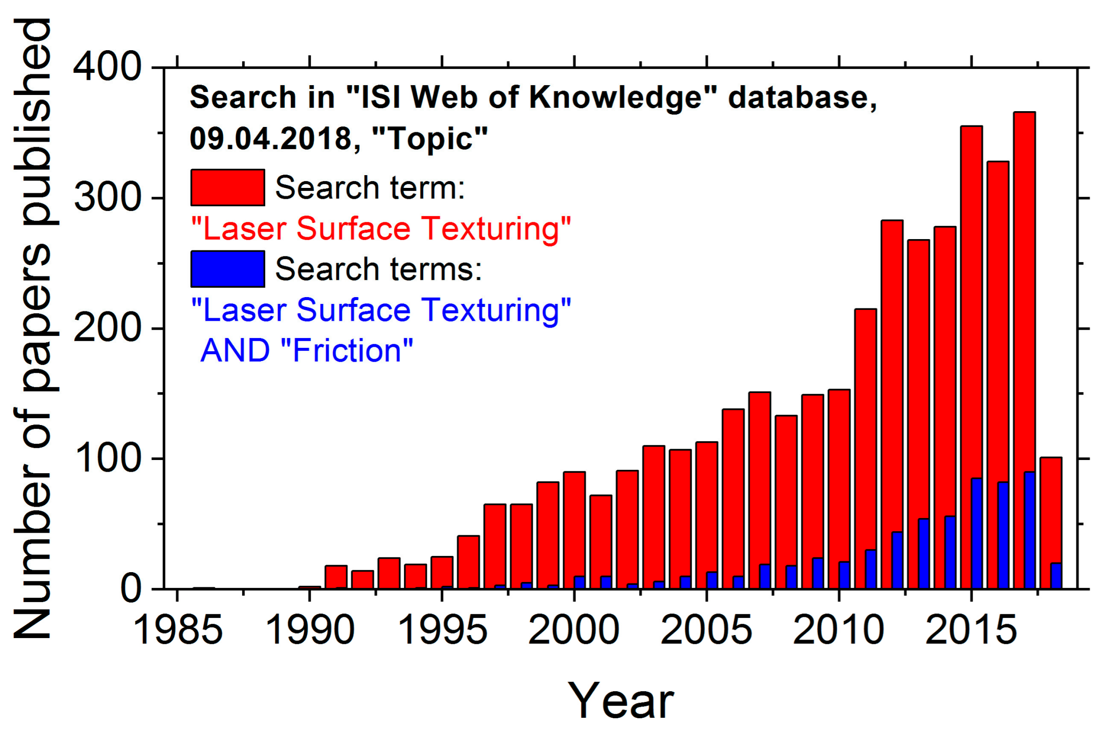
:1. Introduction
2. Definitions, Methods, and Current State
2.1. Definitions
2.2. Test Methods
- Ball-on-disk (BoD): A fixed ball with a specified diameter is pressed against a flat sample surface; the relative motion can be realized by linearly reversing (reciprocating sliding), or by continuous or reversing rotation of the sample at a fixed distance between the tribological contact area and the rotation axis; test parameters are the load, the stroke (twice the amplitude), the reversing or rotational frequency, the number of test cycles or sliding distance, etc. [6].
- Pin-on-disk (PoD): The flat or curved surface of a fixed cylindrical pin with a specified diameter is pressed against a flat sample surface; relative motions and test parameters are the same as for the BoD contact geometry [5].
- Ring-on-disk (RoD): The flat surface of a ring is pressed and rotated against a flat sample surface; test parameters are the same as for the BoD contact geometry [6].
- Block-on-ring (BoR): A block sample is pressed against the curved outer surface of a rotating ring-shaped counterbody; test parameters are the same as for the BoD contact geometry [5].
- Scanning force microscope (SFM): Based on the mechanical contact between a nanometric sharp tip and a surface, the method allows to record a topography of the tested surface; in particular modes, it allows to image tribological properties, e.g., via lateral force measurements [9].
2.3. Basic Ideas behind the Laser Texturing for Tribological Applications
- Laser processing can be used to control the surface roughness via ablation.
- Laser-induced phase transitions, such as melting followed by rapid solidification, can modify the intrinsic material structure. This can increase the hardness of a near surface layer and improve wear resistance.
- Regular dimple, line, or grid patterns generated upon laser-processing at the surface may act as reservoirs for lubricants underneath the tribological contact area.
- Laser-ablated microstructures may act as pockets for storing wear debris particles [16].
- Laser-processing with pulse durations in the µs- to ms-range can generate protruding microstructures, such as annular rims around the dimples or micro-welding dots for increasing the static COF (µs) of metals [17].
- Laser-induced chemical reactions (such as oxidation in ambient air) may additionally affect the surface wetting behavior. Chemically altered surface layers may exhibit different mechanical properties or act as anchors for additive molecules contained in some lubricants.
2.4. Femtosecond Laser Processing of Surfaces
3. Results and Discussion
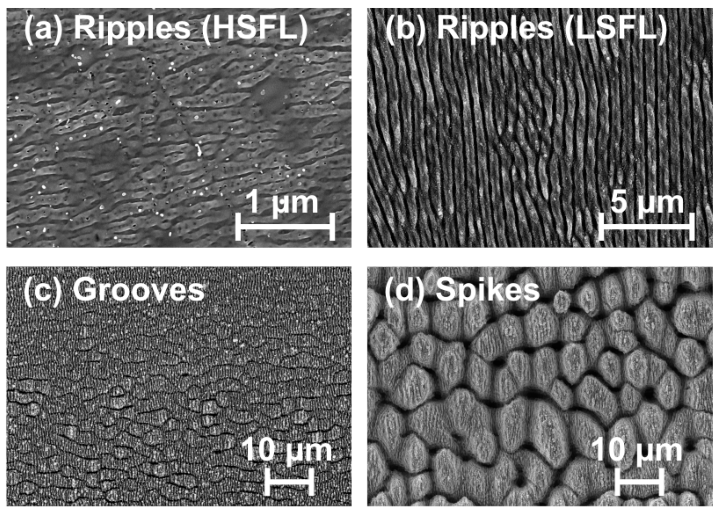
3.1. Self-Ordered Nano- and Microstructures
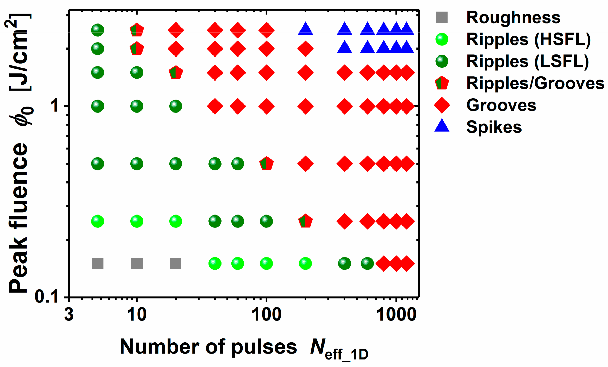
3.1.1. Surface Morphologies
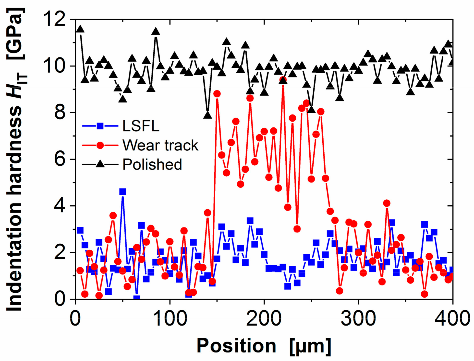
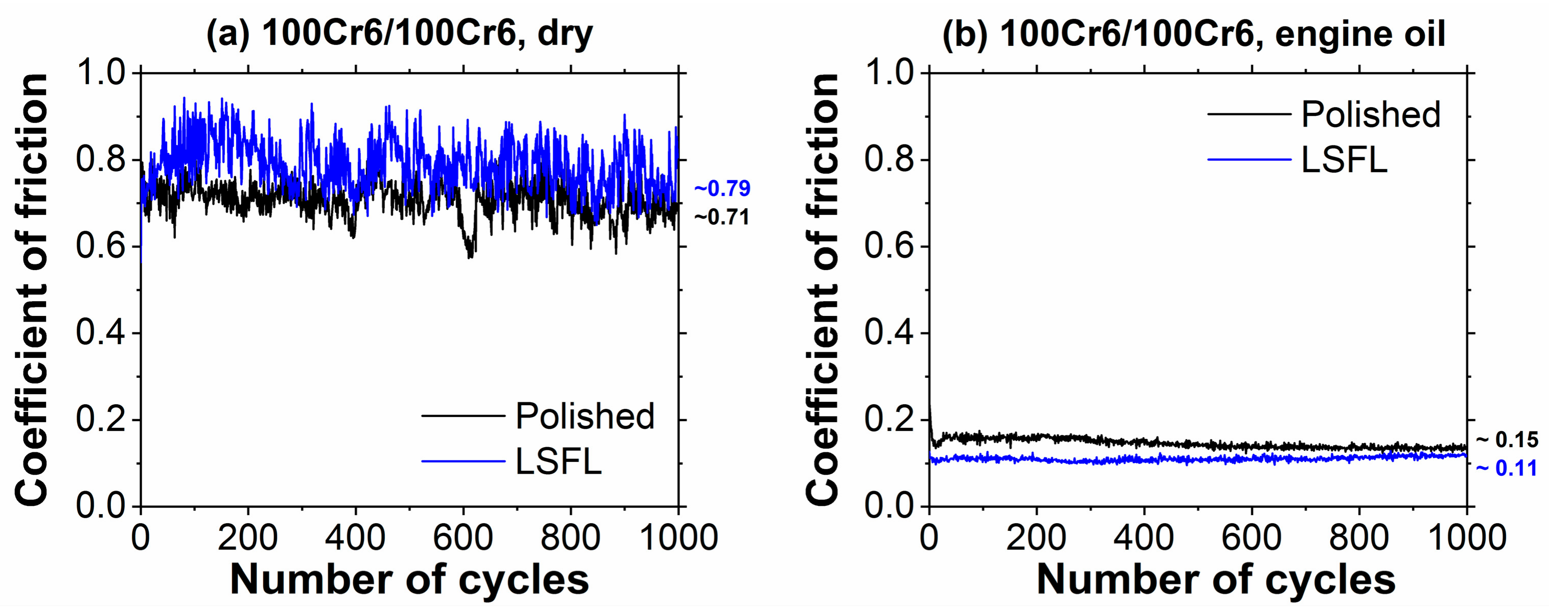
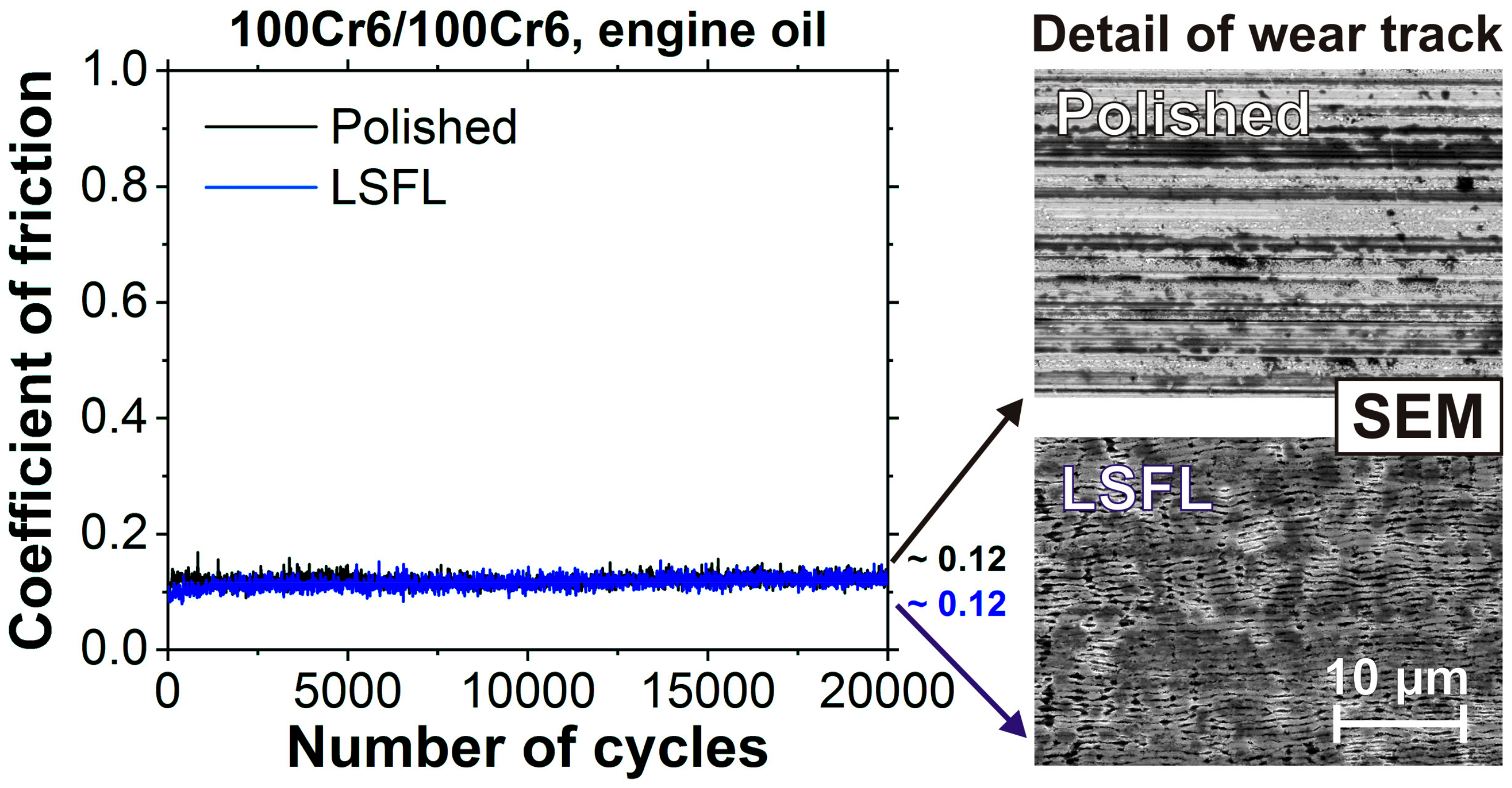
3.1.2. Tribological Performance
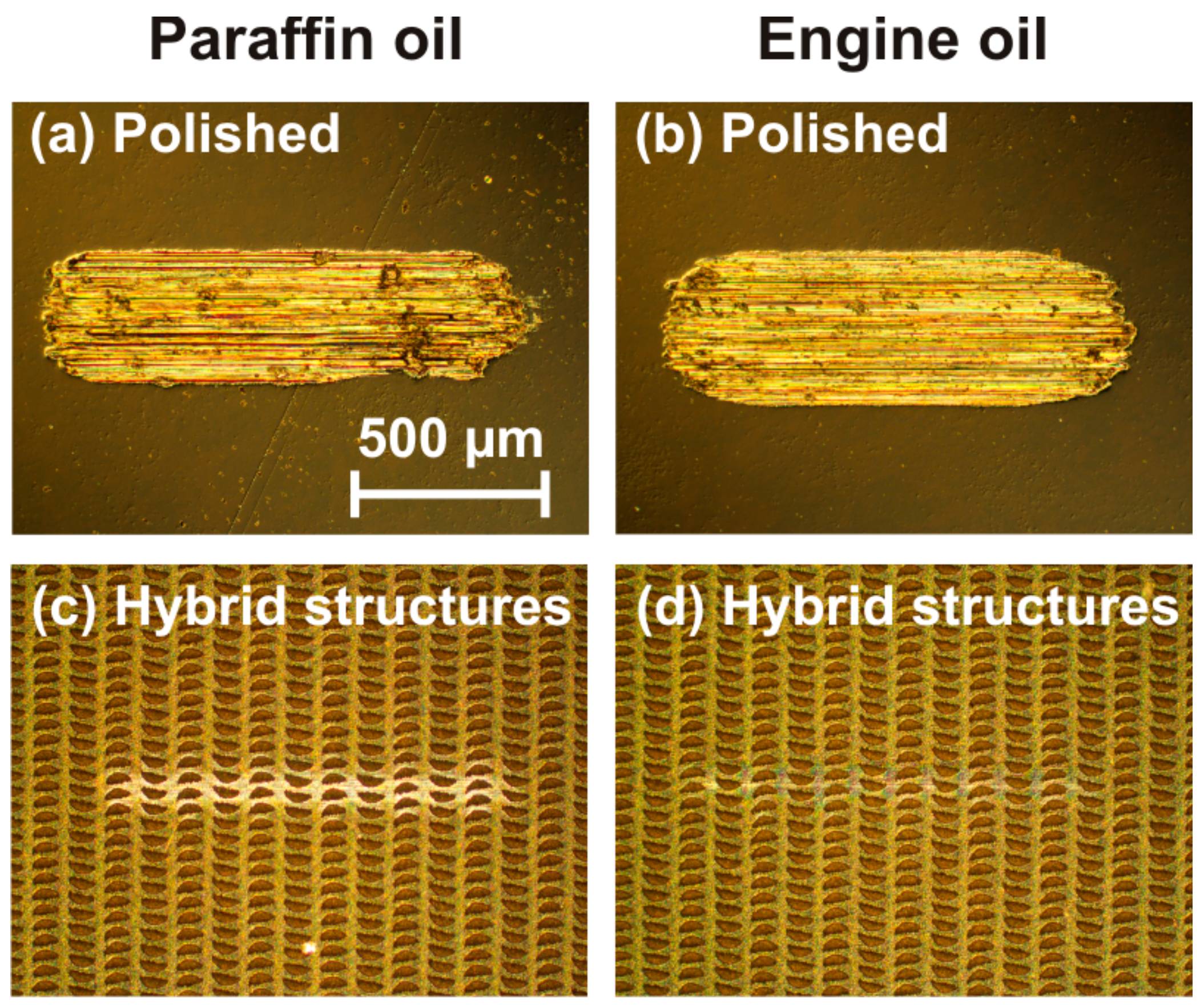
3.2. Hybrid Micro-Nanostructures
3.2.1. Surface Morphologies
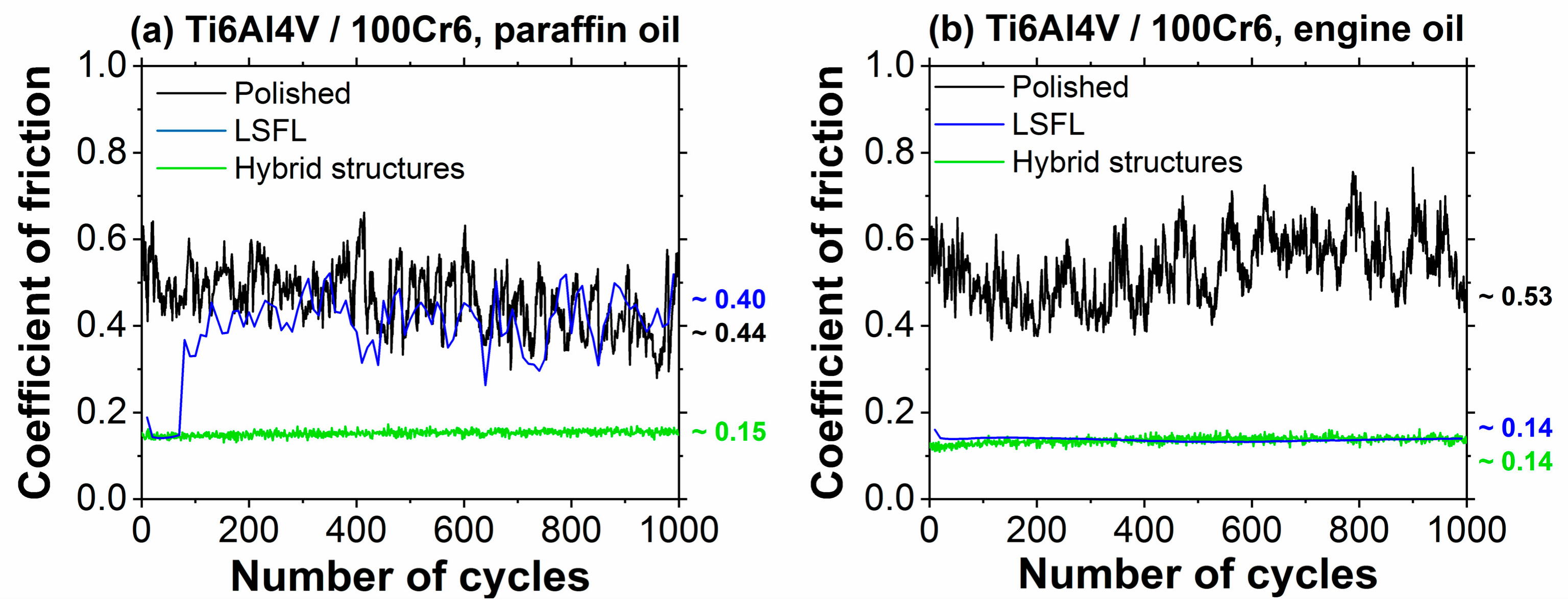
3.2.2. Tribological Performance
4. Future Perspectives
Author Contributions
Funding
Acknowledgments
Conflicts of Interest
References
- Jost, H.P. Lubrication (Tribology), Education and Research: A Report on the Present Position and Industry’s Needs; Department of Education and Science, H.M. Stationary Office: London, UK, 1966. [Google Scholar]
- Neale, M.J. Tribology Handbook; Butterworth & Co.: London, UK, 1973. [Google Scholar]
- Bhushan, B. Modern Tribology Handbook: Volume One; CRC Press: Boca Raton, FL, USA, 2001. [Google Scholar]
- Bartz, W.J. Einführung in die Tribologie und Schmierungstechnik: Tribologie—Schmierstoffe—Anwendungen; Expert-Verlag: Renningen, Germany, 2010. [Google Scholar]
- Stachowiak, G.W.; Batchelor, A.W. Experimental Methods in Tribology; Elsevier: Amsterdam, The Netherlands, 2004. [Google Scholar]
- Czichos, H.; Habig, K.-H. Tribologie-Handbuch– Tribometrie, Tribomaterialien, Tribotechnik, 4th ed.; Springer Vieweg: Wiesbaden, Germany, 2015. [Google Scholar]
- Holmberg, K.; Erdemir, A. Influence of tribology on global energy consumption, costs and emissions. Friction 2017, 5, 263–284. [Google Scholar] [CrossRef]
- Nicholls, M.A.; Do, T.; Norton, P.R.; Kasrai, M.; Bancroft, G.M. Review of the lubrication of metallic surfaces by zinc dialkyl-dithiophosphates. Tribol. Int. 2005, 38, 15–39. [Google Scholar] [CrossRef]
- Bhushan, B. Nanotribology and Nanomechanics I, 3rd ed.; Springer-Verlag: Berlin, Germany, 2011. [Google Scholar]
- Bäuerle, D. Laser Processing and Chemistry, 4th ed.; Springer-Verlag: Berlin, Germany, 2011. [Google Scholar]
- Etsion, I. State of the art in laser surface texturing. J. Tribol. 2005, 127, 248–253. [Google Scholar] [CrossRef]
- Bonse, J.; Höhm, S.; Hartelt, M.; Spaltmann, D.; Pentzien, S.; Rosenfeld, A.; Krüger, J. Tribological performance of sub-100-nm femtosecond laser-induced periodic surface structures on titanium. Appl. Surf. Sci. 2016, 374, 190–196. [Google Scholar] [CrossRef]
- Kovalchenko, A.; Ajayi, O.; Fenske, G.; Erdemir, A.; Etsion, I. The effect of laser surface texturing on transitions in lubrication regimes during unidirectional sliding contact. Tribol. Int. 2005, 38, 219–225. [Google Scholar] [CrossRef]
- Scarraggi, M.; Mezzapesa, F.P.; Carbone, G.; Ancona, A.; Tricarico, L. Friction properties of lubricated laser-microtextured-surfaces: An experimental study from boundary- to hydrodynamic-lubrication. Tribol. Lett. 2013, 49, 117–215. [Google Scholar] [CrossRef]
- Scarraggi, M.; Mezzapesa, F.P.; Carbone, G.; Ancona, A.; Sorgente, D.; Lugarà, P.M. Minimize friction of lubricated laser-microtextured-surfaces by tuning microholes depth. Tribol. Int. 2014, 75, 123–127. [Google Scholar] [CrossRef]
- Geiger, M.; Roth, S.; Becker, W. Influence of laser-produced microstructures on the tribological behaviour of ceramics. Surf. Coat. Technol. 1998, 100, 17–22. [Google Scholar] [CrossRef]
- Schille, J.; Ullmann, F.; Schneider, L.; Graefensteiner, M.; Schiefer, S.; Gerlach, M.; Leidich, E.; Exner, H. Experimental study on laser surface texturing for friction coefficient enhancement. J. Laser Micro Nanoeng. 2015, 10, 245–253. [Google Scholar] [CrossRef]
- Hermens, U.; Kirner, S.V.; Emonts, C.; Comanns, P.; Skoulas, E.; Mimidis, A.; Mescheder, H.; Winands, K.; Krüger, J.; Stratakis, E.; et al. Mimicking lizard-like surface structures upon ultrashort laser pulse irradiation of inorganic materials. Appl. Surf. Sci. 2017, 418, 499–507. [Google Scholar] [CrossRef]
- Kirner, S.V.; Hermens, U.; Mimidis, A.; Skoulas, E.; Florian, C.; Hischen, F.; Plamadeala, C.; Baumgartner, W.; Winands, K.; Mescheder, H.; et al. Mimicking bug-like surface structures and their fluid transport produced by ultrashort laser pulse irradiation of steel. Appl. Phys. A 2017, 123, 754. [Google Scholar] [CrossRef]
- Golloch, R. Untersuchungen zur Tribologie eines Dieselmotors im Bereich Kolbenring/Zylinderlaufbuchse; VDI Verl.: Düsseldorf, Germany, 2001. [Google Scholar]
- Etsion, I.; Sher, E. Improving fuel efficiency with laser surface textured piston rings. Tribol. Int. 2009, 42, 542–547. [Google Scholar] [CrossRef]
- Berlin, T. Funktionale Laser-Mikrostrukturierung zur Verschleiß- und Verbrauchsreduktion an Hochbeanspruchten Bauteiloberflächen. Ergebnisbericht des BMBF Verbundprojekts “SmartSurf“. Im Rahmenkonzept “Forschung für die Produktion von Morgen“. Innovationsplattform “Ressourceneffizienz in der Produktion“—kurz Effizienzfabrik. Zeitraum: September 2009 bis zum März 2013; BMBF-Forschungsbericht; Bundesministerium für Bildung und Forschung: Bonn, Germany, 2013. [Google Scholar]
- Küper, S.; Stuke, M. Femtosecond UV Excimer laser ablation. Appl. Phys. B 1987, 44, 199–204. [Google Scholar] [CrossRef]
- Srinivasan, R.; Sutcliffe, E.; Braren, B. Ablation and etching of polymethylmethacrylate by very short (160 fs) ultraviolet (308 nm) laser pulses. Appl. Phys. Lett. 1987, 51, 1285–1287. [Google Scholar] [CrossRef]
- Bonse, J.; Krüger, J. Probing the heat affected zone by chemical modifications in femtosecond pulse laser ablation of titanium nitride films in air. J. Appl. Phys. 2010, 107, 054902. [Google Scholar] [CrossRef]
- Wang, Z.; Zhao, Q.; Wang, C.; Zhao, Y. Modulation of dry tribological property of stainless steel by femtosecond laser surface texturing. Appl. Phys. A 2015, 119, 1155–1163. [Google Scholar] [CrossRef]
- Wang, Z.; Li, Y.B.; Wang, C.; Zhao, Y. Angle-dependent lubricated tribological properties of stainless steel by femtosecond laser surface texturing. Opt. Laser Technol. 2016, 81, 60–66. [Google Scholar] [CrossRef]
- Lasagni, A.F.; Gachot, C.; Trinh, K.E.; Hans, M.; Rosenkranz, A.; Roch, T.; Eckhardt, S.; Kunze, T.; Bieda, M.; Günther, D.; et al. Direct laser interference patterning, 20 years of development: from the basics to industrial applications. In Laser-Based Micro- and Nanoprocessing XI; SPIE: Bellingham, WA, USA, 2017; Volume 10092. [Google Scholar]
- Gachot, C.; Rosenkranz, A.; Reinert, L.; Ramos-Moore, E.; Souza, N.; Müser, M.H.; Mücklich, F. Dry friction between laser-patterned surfaces: role of alignment, structural wavelength and surface chemistry. Tribol. Lett. 2013, 49, 193–202. [Google Scholar] [CrossRef]
- Rosenkranz, A.; Reinert, L.; Gachot, C.; Aboufadl, H.; Grandthyll, S.; Jacobs, K.; Müller, F.; Mücklich, F. Oxide formation, morphology, and nanohardness of laser-patterned steel surfaces. Adv. Eng. Mater. 2015, 17, 1234–1242. [Google Scholar] [CrossRef]
- Bonse, J.; Krüger, J.; Höhm, S.; Rosenfeld, A. Femtosecond laser-induced periodic surface structures. J. Laser Appl. 2012, 24, 042006. [Google Scholar] [CrossRef]
- Bonse, J.; Höhm, S.; Kirner, S.V.; Rosenfeld, A.; Krüger, J. Laser-induced periodic surface structures—A scientific evergreen. IEEE J. Sel. Top. Quantum Electron. 2017, 23, 9000615. [Google Scholar] [CrossRef]
- Van Driel, H.M.; Sipe, J.E.; Young, J.F. Laser-induced periodic surface-structure on solids—A universal phenomenon. Phys. Rev. Lett. 1982, 49, 1955–1958. [Google Scholar] [CrossRef]
- Rudenko, A.; Colombier, J.P.; Höhm, S.; Rosenfeld, A.; Krüger, J.; Bonse, J.; Itina, T.E. Spontaneous periodic ordering on the surface and in the bulk of dielectrics irradiated by ultrafast laser: A shared electromagnetic origin. Sci. Rep. 2017, 7, 12306. [Google Scholar] [CrossRef] [PubMed]
- Abere, M.J.; Zhong, M.L.; Krüger, J.; Bonse, J. Ultrafast laser-induced morphological transformations. MRS Bull. 2017, 41, 969–974. [Google Scholar] [CrossRef]
- Vorobyev, A.Y.; Guo, C. Colorizing metals with femtosecond laser pulses. Appl. Phys. Lett. 2008, 92, 041914. [Google Scholar] [CrossRef]
- Dusser, B.; Sagan, Z.; Soder, H.; Faure, N.; Colombier, J.P.; Jourlin, M.; Audouard, E. Controlled nanostructures formation by ultra fast laser pulses for color marking. Opt. Express 2010, 18, 2913–2924. [Google Scholar] [CrossRef] [PubMed]
- Zorba, V.; Stratakis, E.; Barberoglou, M.; Spanakis, E.; Tzanetakis, P.; Fotakis, C. Tailoring the wetting response of silicon surfaces via fs laser structuring. Appl. Phys. A 2008, 93, 819–825. [Google Scholar] [CrossRef]
- Kietzig, A.M.; Hatzikiriakos, S.G.; Englezos, P. Patterned superhydrophobic metallic surfaces. Langmuir 2009, 25, 4821–4827. [Google Scholar] [CrossRef] [PubMed]
- Müller, F.A.; Kunz, C.; Gräf, S. Bio-inspired functional surfaces based on laser-induced periodic surface structures. Materials 2016, 9, 476. [Google Scholar] [CrossRef]
- Epperlein, N.; Menzel, F.; Schwibbert, K.; Koter, R.; Bonse, J.; Sameith, J.; Krüger, J.; Toepel, J. Influence of femtosecond laser produced nanostructures on biofilm growth on steel. Appl. Surf. Sci. 2017, 418, 420–424. [Google Scholar] [CrossRef]
- Bonse, J.; Kirner, S.V.; Höhm, S.; Epperlein, N.; Spaltmann, D.; Rosenfeld, A.; Krüger, J. Applications of laser-induced periodic surface structures (LIPSS). In Laser-Based Micro- and Nanoprocessing XI; SPIE: Bellingham, WA, USA, 2017; Volume 10092. [Google Scholar]
- Yu, J.J.; Lu, Y.F. Laser-induced ripple structures on Ni-P substrates. Appl. Surf. Sci. 1999, 148, 248–252. [Google Scholar] [CrossRef]
- Yasumaru, N.; Miyazaki, K.; Kiuchi, J.; Sentoku, E. Frictional properties of diamond-like carbon glassy carbon and nitrides with femtosecond-laser-induced nanostructure. Diam. Relat. Mater. 2011, 20, 542–545. [Google Scholar] [CrossRef]
- Bonse, J.; Kirner, S.V.; Koter, R.; Pentzien, S.; Spaltmann, D.; Krüger, J. Femtosecond laser-induced periodic surface structures on titanium nitride coatings for tribological applications. Appl. Surf. Sci. 2017, 418, 572–579. [Google Scholar] [CrossRef]
- Mizuno, A.; Honda, T.; Kiuchi, J.; Iwai, Y.; Yasumaru, N.; Miyazaki, K. Friction properties of the DLC film with periodic structures in nano-scale. Tribol. Online 2006, 1, 44–48. [Google Scholar] [CrossRef]
- Yasumaru, N.; Miyazaki, K.; Kiuchi, J. Control of tribological properties of diamond-like carbon films with femtosecond-laser-induced nanostructuring. Appl. Surf. Sci. 2008, 254, 2364–2368. [Google Scholar] [CrossRef]
- Pfeiffer, M.; Engel, A.; Gruettner, H.; Guenther, K.; Marquardt, F.; Reisse, G.; Weissmantel, S. Ripple formation in various metals and super-hard tetrahedral amorphous carbon films in consequence of femtosecond laser irradiation. Appl. Phys. A Mater. Sci. Process. 2013, 110, 655–659. [Google Scholar] [CrossRef]
- Kawahara, K.; Sawada, H.; Mori, A. Effect of surface periodic structures for bi-directional rotation on water lubrication properties of SiC. Tribol. Online 2008, 3, 122–126. [Google Scholar] [CrossRef]
- Chen, C.Y.; Chung, C.J.; Wu, B.H.; Li, W.L.; Chien, C.W.; Wu, P.H.; Cheng, C.W. Microstructure and lubricating property of ultra-fast laser pulse textured silicon carbide seals. Appl. Phys. A 2012, 107, 345–350. [Google Scholar] [CrossRef]
- Chen, C.Y.; Wu, B.H.; Chung, C.J.; Li, W.L.; Chien, C.-W.; Wu, P.-H.; Cheng, C.W. Low-friction characteristics of nanostructured surfaces on silicon carbide for water-lubricated seals. Tribol. Lett. 2013, 51, 127–133. [Google Scholar] [CrossRef]
- Eichstädt, J.; Römer, G.R.B.E.; Huis in’t Veld, A.J. Towards friction control using laser-induced periodic surface structures. Phys. Proced. 2011, 12, 7–15. [Google Scholar] [CrossRef]
- Bonse, J.; Koter, R.; Hartelt, M.; Spaltmann, D.; Pentzien, S.; Höhm, S.; Rosenfeld, A.; Krüger, J. Femtosecond laser-induced periodic surface structures on steel and titanium alloy for tribological applications. Appl. Phys. A 2014, 117, 103–110. [Google Scholar] [CrossRef]
- Bonse, J.; Koter, R.; Hartelt, M.; Spaltmann, D.; Pentzien, S.; Höhm, S.; Rosenfeld, A.; Krüger, J. Tribological performance of femtosecond laser-induced periodic surface structures on titanium and a high toughness bearing steel. Appl. Surf. Sci. 2015, 336, 21–27. [Google Scholar] [CrossRef]
- Wang, Z.; Zhao, Q.Z.; Wang, C.W. Reduction of friction of metals using laser-induced periodic surface nanostructures. Micromachines 2015, 6, 1606–1616. [Google Scholar] [CrossRef]
- Gnilitskyi, I.; Rotundo, F.; Martini, C.; Pavlov, I.; Ilday, S.; Vovk, E.; Ilday, F.Ö.; Orazi, L. Nano patterning of AISI 316L stainless steel with nonlinear laser lithography: Sliding under dry and oil-lubricated conditions. Tribol. Int. 2016, 99, 67–76. [Google Scholar] [CrossRef]
- Voyer, J.; Ausserer, F.; Klien, S.; Ristow, A.; Velkavrh, I.; Diem, A.; Zehetner, J.; Stroj, S.; Heidegger, S.; Bertschler, C.; et al. Sub-micro laser modifications of tribological surfaces. Mater. Perform. Charact. 2017, 6, 42–67. [Google Scholar] [CrossRef]
- Kawasegi, N.; Sugimori, H.; Morimoto, H.; Morita, N.; Hori, I. Development of cutting tools with microscale and nanoscale textures to improve frictional behavior. Precis. Eng. 2009, 33, 248–254. [Google Scholar] [CrossRef]
- Deng, J.; Lian, Y.; Wu, Z.; Xing, Y. Performance of femtosecond laser-textured cutting tools deposited with WS2 solid lubricant coatings. Surf. Coat. Technol. 2013, 222, 135–143. [Google Scholar] [CrossRef]
- Xing, Y.; Deng, J.; Zhang, K.; Zhang, G.; Gao, H. Effect of femtosecond laser pretreatment on wear resistance of Al2O3/TiC ceramic tools in dry cutting. Int. J. Refract. Met. Hard Mater. 2014, 43, 291–301. [Google Scholar] [CrossRef]
- Zhang, K.; Deng, J.; Ding, Z.; Guo, X.; Sun, L. Improving dry machining performance of TiAlN hard-coated tools through combined technology of femtosecond laser-textures and WS2 soft-coatings. J. Manuf. Process. 2017, 30, 492–501. [Google Scholar] [CrossRef]
- Bonse, J.; Mann, G.; Krüger, J.; Marcinkowski, M.; Eberstein, M. Femtosecond laser-induced removal of silicon nitride layers from doped and textured silicon wafers used in photovoltaics. Thin Solid Films 2013, 542, 420–425. [Google Scholar] [CrossRef]
- Klaffke, D.; Hartelt, M. Tribological characterization of thin hard coatings by reciprocating sliding tests. Tribol. Lett. 1995, 1, 265–276. [Google Scholar] [CrossRef]
- Bonse, J.; Höhm, S.; Hartelt, M.; Spaltmann, D.; Pentzien, S.; Koter, R.; Marschner, S.; Rosenfeld, A.; Krüger, J. Femtosecond laser-induced surface nanostructures for tribological applications. In Optically-Induced Nanostructures; König, K., Ostendorf, A., Eds.; Walther De Gruyter: Berlin, Germany, 2015; pp. 141–156. [Google Scholar]
- ISO. Metallic Materials—Instrumented Indentation Test for Hardness and Materials Parameters; ISO 14577; International Organization for Standardization: Geneva, Switzerland, 2015. [Google Scholar]
- Kirner, S.V.; Slachciak, N.; Elert, A.M.; Griepentrog, M.; Fischer, D.; Hertwig, A.; Sahre, M.; Dörfel, I.; Sturm, H.; Pentzien, S.; et al. Tribological performance of titanium samples oxidized by fs-laser radiation, thermal heating, or electrochemical anodization. Appl. Phys. A 2018, 124, 326. [Google Scholar] [CrossRef]
- Eaton, S.M.; Ng, M.L.; Bonse, J.; Mermillod-Blondin, A.; Zhang, H.; Rosenfeld, A.; Herman, P.R. Low-loss waveguides fabricated in BK7 glass by high repetition rate femtosecond fiber laser. Appl. Opt. 2008, 47, 2098–2102. [Google Scholar] [CrossRef] [PubMed]
- Kirner, S.V.; Wirth, T.; Sturm, H.; Krüger, J.; Bonse, J. Nanometer-resolved chemical analyses of femtosecond laser-induced periodic surface structures on titanium. J. Appl. Phys. 2017, 122, 104901. [Google Scholar] [CrossRef]


| Surface | COF µk (Dry) | COF µk (Engine Oil) |
|---|---|---|
| Non-irradiated | 0.71 | 0.15 |
| LSFL 1 | 0.79 | 0.11 |
| Grooves 1 | 0.73 | 0.13 |
| Spikes 1 | 0.70 | 0.15 |
© 2018 by the authors. Licensee MDPI, Basel, Switzerland. This article is an open access article distributed under the terms and conditions of the Creative Commons Attribution (CC BY) license (http://creativecommons.org/licenses/by/4.0/).
Share and Cite
Bonse, J.; Kirner, S.V.; Griepentrog, M.; Spaltmann, D.; Krüger, J. Femtosecond Laser Texturing of Surfaces for Tribological Applications. Materials 2018, 11, 801. https://doi.org/10.3390/ma11050801
Bonse J, Kirner SV, Griepentrog M, Spaltmann D, Krüger J. Femtosecond Laser Texturing of Surfaces for Tribological Applications. Materials. 2018; 11(5):801. https://doi.org/10.3390/ma11050801
Chicago/Turabian StyleBonse, Jörn, Sabrina V. Kirner, Michael Griepentrog, Dirk Spaltmann, and Jörg Krüger. 2018. "Femtosecond Laser Texturing of Surfaces for Tribological Applications" Materials 11, no. 5: 801. https://doi.org/10.3390/ma11050801
APA StyleBonse, J., Kirner, S. V., Griepentrog, M., Spaltmann, D., & Krüger, J. (2018). Femtosecond Laser Texturing of Surfaces for Tribological Applications. Materials, 11(5), 801. https://doi.org/10.3390/ma11050801