Application of Recycled Ceramic Aggregates for the Production of Mineral-Asphalt Mixtures


 ,
, 
Abstract
:1. Introduction
2. Materials and Methods
2.1. Material Properties
2.2. Designing Method of the Mixture
- F—specific surface area of the designer mineral mixture, (m2/kg)
- g—content of the fraction >4 mm, (%)
- z—content of the fraction >0.25 ≤ 4 mm, (%)
- s—content of the fraction >0.063 to ≤0.25 mm, (%)
- f—content of the fraction ≤0.063, (%)
- ρa—density of the mineral mixture, (g/cm3)
- Ak—content of binder in relation to the mineral mixture, (%)
- F—specific surface area of the mineral mixture, (m2/kg)
- B—thickness of bituminous film, (μm)
- ρasf—binder density, (g/cm3)
- -
- 35/50 asphalt—3.2–2.7 μm
- -
- 50/70 asphalt—2.8–2.4 μm
- -
- 70/100 asphalt—2.6–2.2 μm
- -
- 100/150 asphalt—2.2–1.7 μm.
2.3. Methods
- Mm—mass of the mineral-asphalt mixture, (g)
- Mk—mass of aggregate excluding the filler in the extraction thimble, (g)
- m1—mass of the extraction thimble with filter prior to extraction, (g)
- m2—mass of the extraction thimble with filter after extraction, (g).
- Vp —pycnometer volume, (cm3)
- ρw—density of distilled water assumed for the temperature of the experiment, (g/cm3)
- m1—mass of the pycnometer with the head, (g)
- m2—mass of the pycnometer with the head and mineral-asphalt sample, (g)
- m3—mass of the pycnometer with the head, sample and distilled water, (g).
- ρw—density of distilled water assumed for the temperature of the experiment, (g/cm3)
- m1—mass of a dry sample, (g)
- m2—mass of a sample saturated with water, (g)
- m3—mass of a surface dry, saturated sample, (g).
- Vm—content of voids in a sample of the mineral-asphalt mixture up to 0.1%,
- ρm—density of the mineral-asphalt mixture, (g/cm3)
- ρb—bulk density (g/cm3).
- VMA—corresponds to the content of voids in the mineral mixture, expressed in %, which can be calculated by means of the Equation (8) [24],
- B—content of binder in the mineral-asphalt mixture, (%)
- ρb—bulk density of a mineral-asphalt mixture sample, (g/cm3)
- ρB—binder density, (g/cm3)
- Vm—content of voids in the mineral-asphalt mixture, (%).
- ITSw—stands for the average strength of the wet samples, rounded up to an integer, which can be calculated from Equation (10) [35],
- Pw—maximum value of the compressive strength for the wet samples (kN)
- Pd—maximum value of the compressive strength for the dry samples (kN)
- D—sample diameter rounded up to 0.1 (mm),
- H—sample height rounded up to 0.1 (mm).
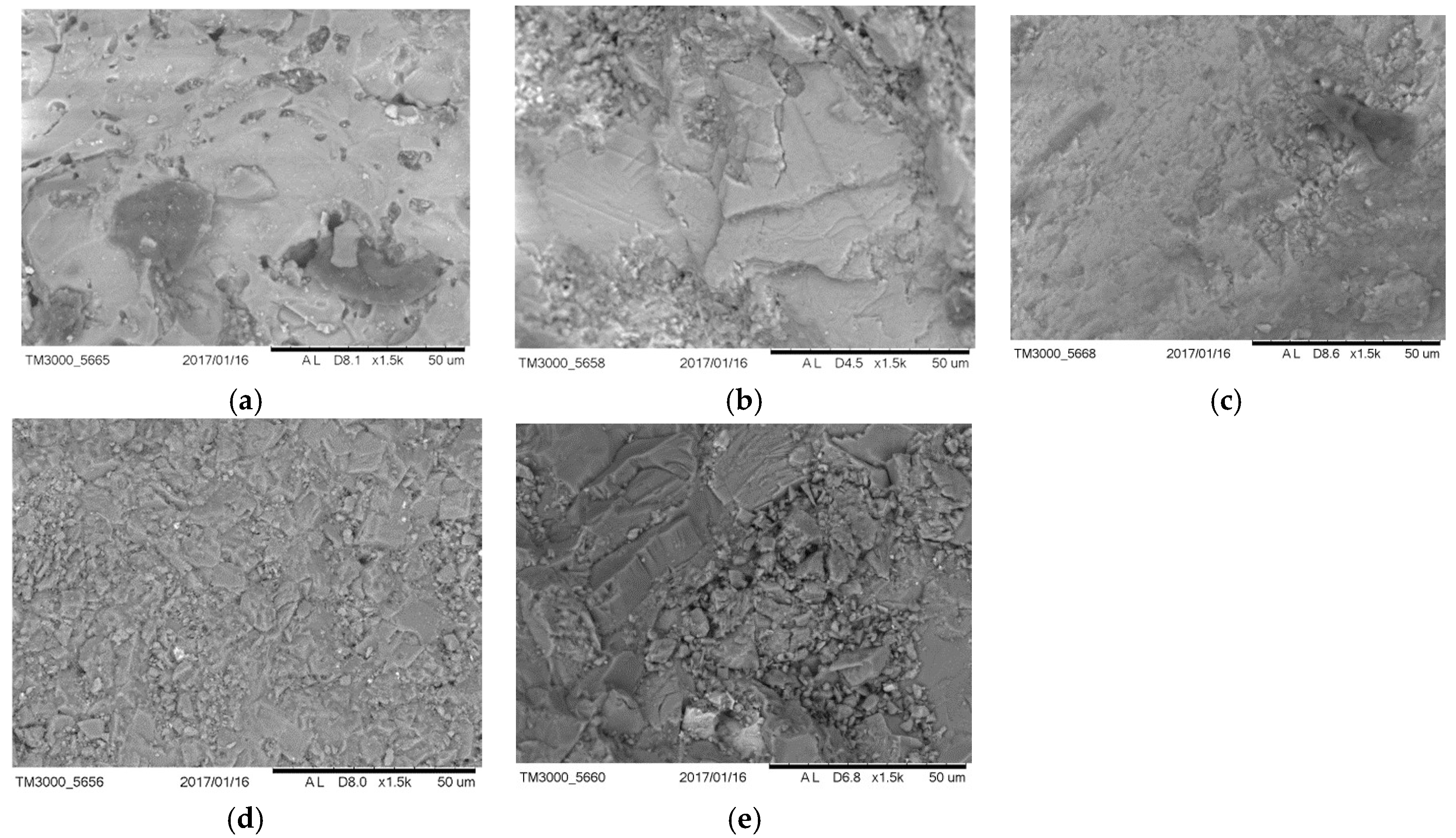
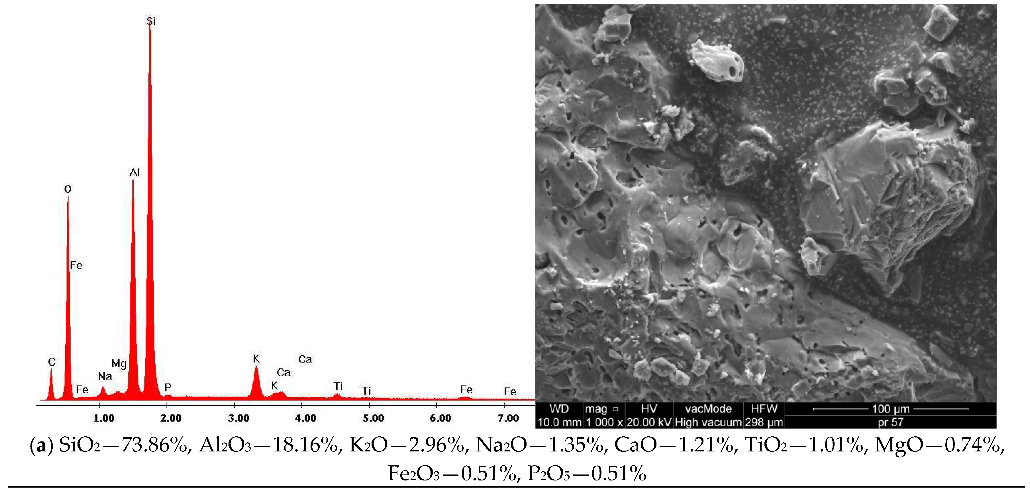
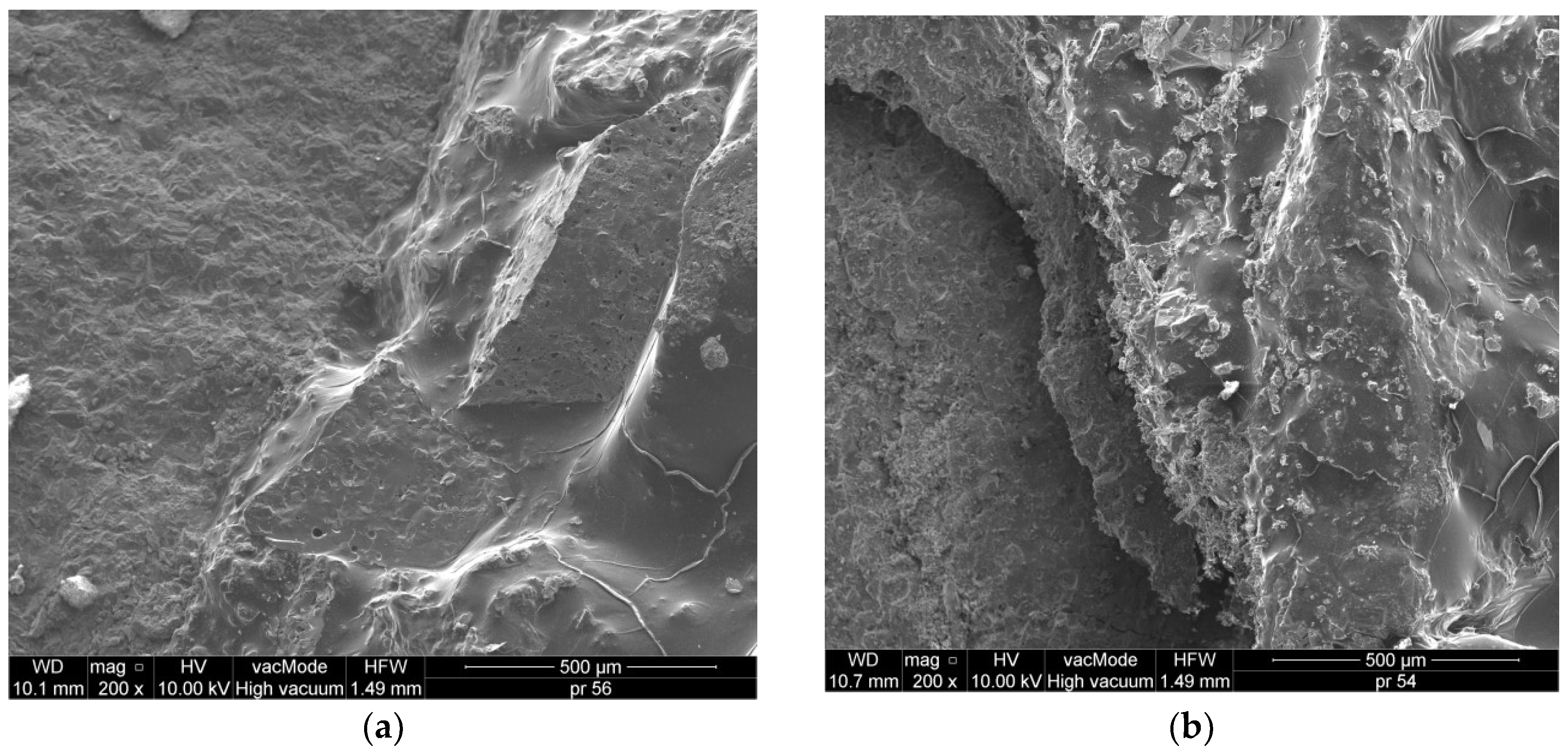
2.4. Scanning Electron Microscopy with EDS Analysis
3. Results
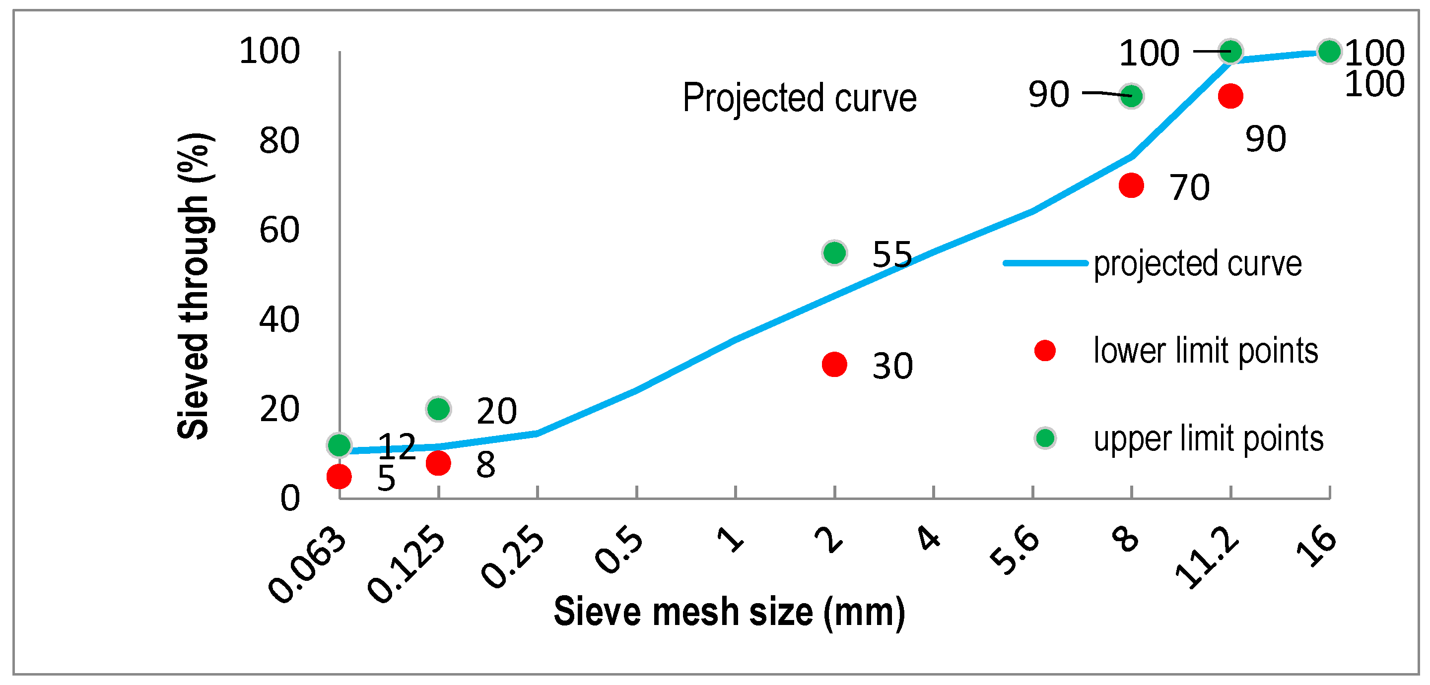
- −8 ± +5 for the aggregates stopped on the 11.2 mm sieve,
- ±7 for the aggregates stopped on the 5.6 mm sieve,
- ±6 for the aggregates stopped on the 2.0 mm sieve,
- ±4 for the aggregates stopped on the 0.125 mm sieve,
- ±2 for the aggregates stopped on the 0.063 mm sieve.
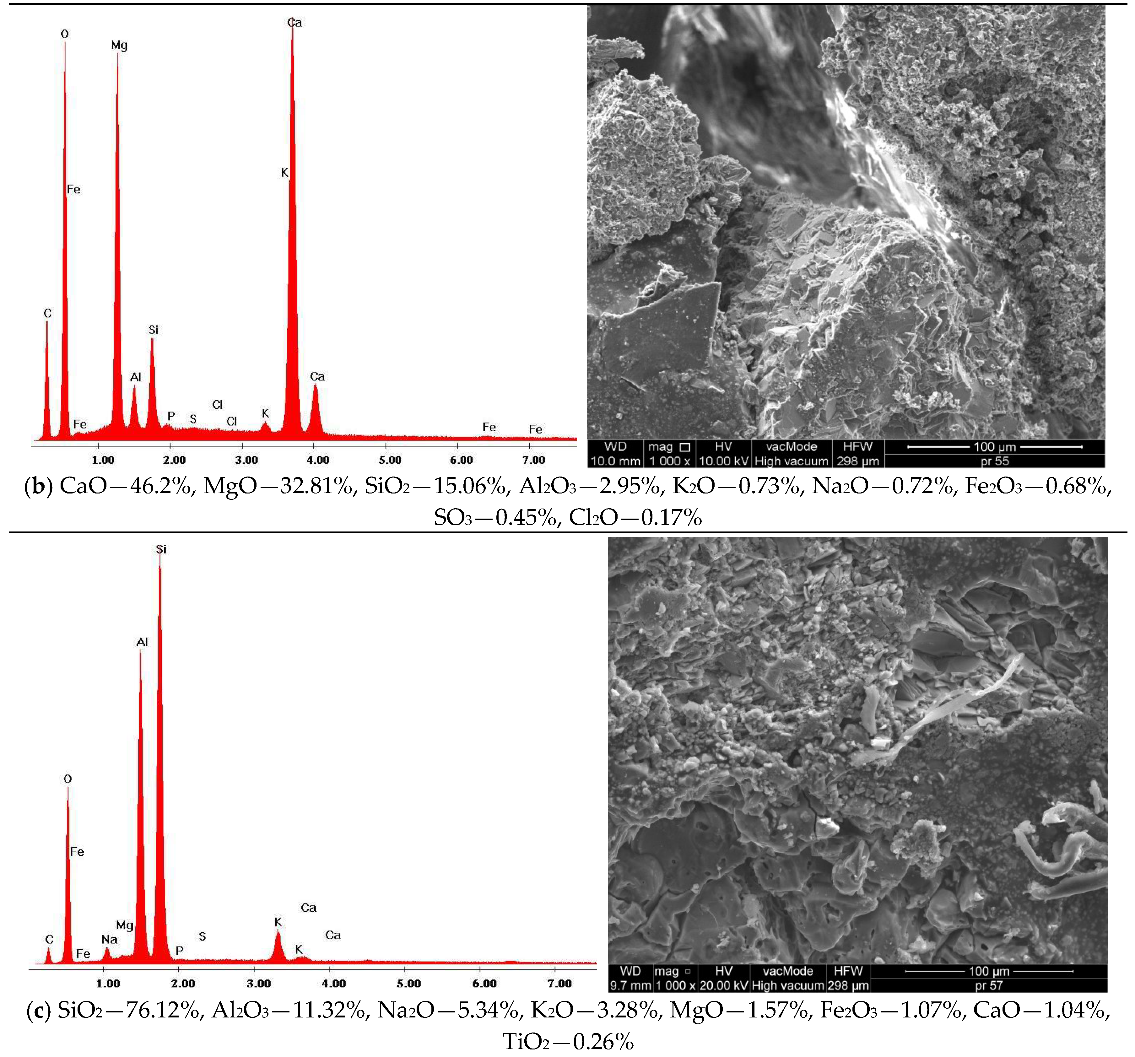
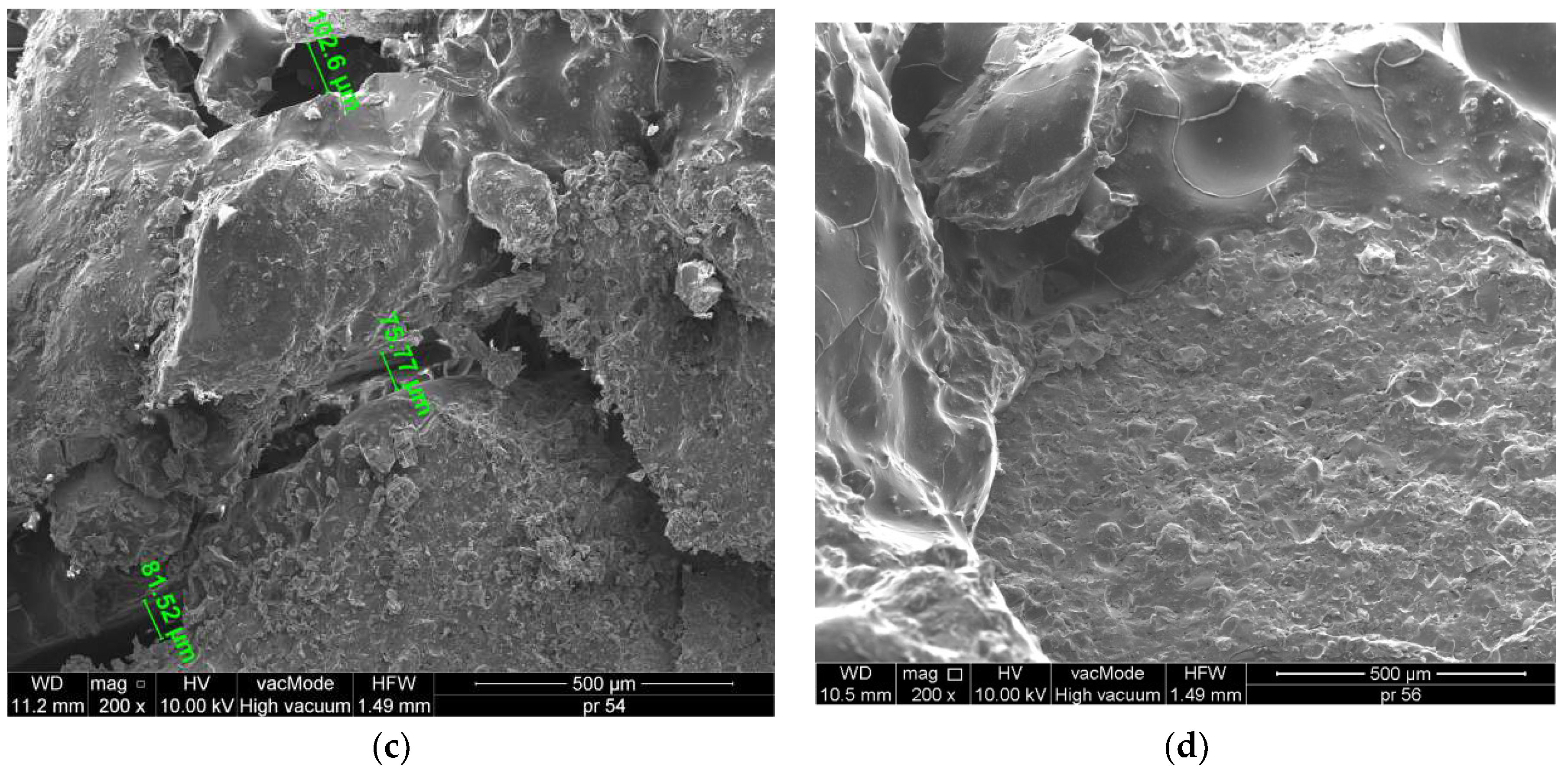
Scanning Electron Microscopy with EDS Analysis
4. Conclusions
- a.
- The obtained results of soluble binder content and aggregate produced after the extraction, conducted for the mixtures in each series, are comparable for typical mineral-asphalt mixtures and do not exceed the standard values.
- b.
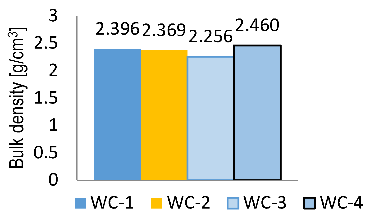
- The study on the density and bulk density of the mineral-asphalt mixture, on the basis of which the content of voids in the mineral-asphalt mixture and the mineral mixture filled with binder were calculated, indicates that these parameters are within the ranges of the standard requirements. The ceramic aggregate addition increased the void content in MAM by 15% through increased asphalt absorption and porous structure of the material.
- c.
- The microstructure investigation indicated a very good adhesion of asphalt to the carbonate and ceramic aggregate. On the other hand, wide cracks appeared in the mixture with granodiorite, increasing the void content in MAM and reducing the bulk density of the mixture.
- d.
- The highest resistance to water and frost was obtained in the mixture with dolomite WC-4 as well as dolomite and waste sanitary ceramics aggregate WC-1 and WC-2. The highest ITSR was obtained for WC-4 MAM and it was 24% higher than ITSR for WC-3 mixture.
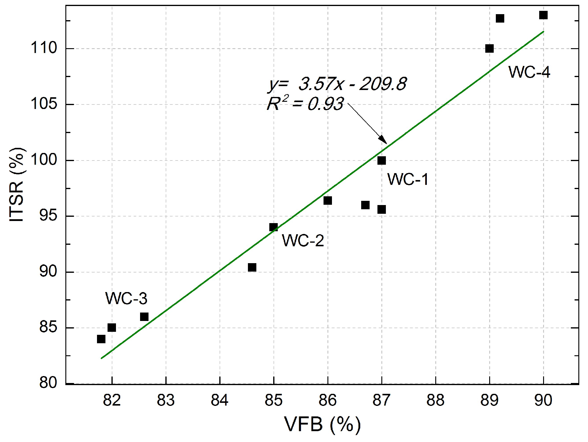
- e.
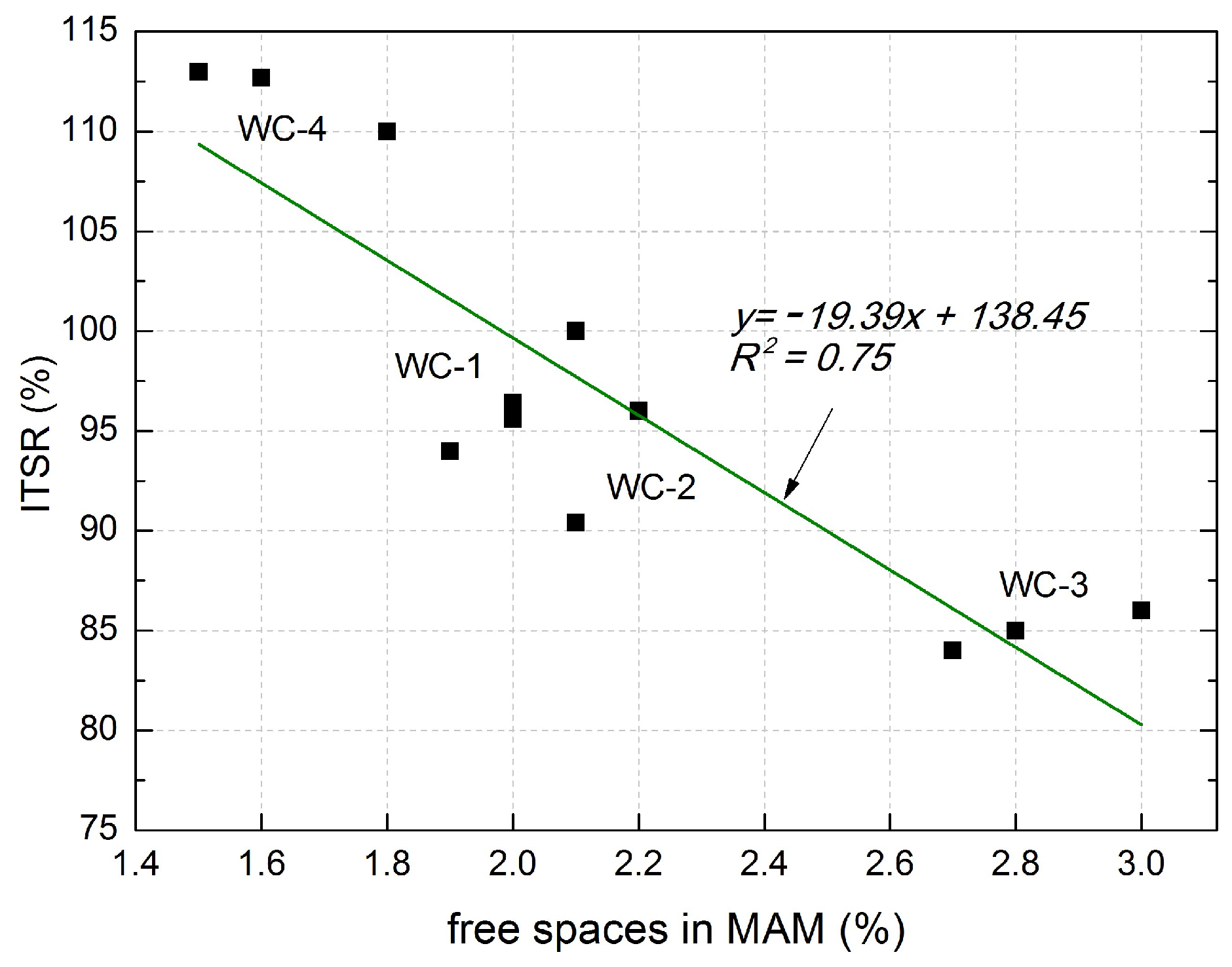
- A very good correlation between the content of voids in the MM filled with binder, as well as void content in MAM and the ITSR – corresponding to the resistance to water and frost – was obtained.
- f.
- The conducted research indicates that ceramics may be successfully applied in the asphalt mixtures intended for use in the wearing course based on carbonate aggregates, i.e., dolomite. The mixture with 20 and 30% addition of recycled ceramic aggregate, used as a partial substitution of the natural dolomite aggregate, meets the majority of requirements related to mechanical properties stated in the technical specification.
Author Contributions
Acknowledgments
Conflicts of Interest
References
- Dondi, M.; Cappelletti, P.; D’Amore, M.; de Gennaro, R.; Graziano, S.F.; Langella, A.; Raimondo, M.; Zanelli, C. Lightweight aggregates from waste materials: Reappraisal of expansion behavior and prediction schemes for bloating. Constr. Build. Mater. 2016, 127, 394–409. [Google Scholar] [CrossRef]
- Siddique, R.; Cachim, P. Waste and Supplementary Cementitious Materials in Concrete: Characterisation, Properties and Applications; Woodhead Publishing: Cambridge, UK, 2018; p. 570. ISBN 9780081021569. [Google Scholar]
- Moreno-Maroto, J.M.; Gonzalez-Corrochano, B.; Alonso-Azcarate, J.; Rodríguez, L.; Acosta, A. Development of lightweight aggregates from stone cutting sludge, plastic wastes and sepiolite rejections for agricultural and environmental purposes. J. Environ. Manag. 2017, 200, 229–242. [Google Scholar] [CrossRef] [PubMed]
- Liu, M.; Xu, G.; Li, G. Effect of the ratio of components on the characteristics of lightweight aggregate made from sewage sludge and river sediment. Process Saf. Environ. Prot. 2017, 105, 109–116. [Google Scholar] [CrossRef]
- Li, B.; Ling, T.C.; Qu, L.; Wang, Y. Effects of a two-step heating process on the properties of lightweight aggregate prepared with sewage sludge and saline clay. Constr. Build. Mater. 2016, 114, 119–126. [Google Scholar] [CrossRef]
- Franus, M.; Jozefaciuk, G.; Bandura, L.; Lamorski, K.; Hajnos, M.; Franus, W. Modification of lightweight aggregates’ microstructure by used motor oil addition. Materials 2016, 9, 845. [Google Scholar] [CrossRef] [PubMed]
- Smarzewski, P.; Barnat-Hunek, D. Mechanical and durability related properties of high performance concrete made with coal cinder and waste foundry sand. Constr. Build. Mater. 2016, 121, 9–17. [Google Scholar] [CrossRef]
- Suchorab, Z.; Barnat-Hunek, D.; Franus, M.; Łagód, G. Mechanical and physical properties of hydrophobized lightweight aggregate concrete with sewage sludge. Materials 2016, 9, 317. [Google Scholar] [CrossRef] [PubMed]
- Miličević, I.; Štirmer, N.; Pečur, I.B. Residual Mechanical Properties of Concrete Made with Crushed Clay Bricks and Roof Tiles Aggregate after Exposure to High Temperatures. Materials 2016, 9, 295. [Google Scholar] [CrossRef] [PubMed]
- Rashid, K.; Razzaq, A.; Ahmad, M.; Rashid, T.; Tariq, S. Experimental and analytical selection of sustainable recycled concrete with ceramic waste aggregate. Constr. Build. Mater. 2017, 154, 829–840. [Google Scholar] [CrossRef]
- Guerra, I.; Vivar, I.; Liamas, B.; Juan, A.; Moran, J. Eco-efficient concretes: the effects of using recycled ceramic material from sanitary installations on the mechanical properties of concrete. Waste Manag. 2009, 29, 643–646. [Google Scholar] [CrossRef] [PubMed]
- Medina, C.; Frías, M.; Sánchez de Rojas, M.I. Microstructure and properties of recycled concretes using sanitary ware industry waste as coarse aggregate. Constr. Build. Mater. 2012, 31, 112–118. [Google Scholar] [CrossRef]
- Senthamarai, R.M.; Manoharan, P.D.; Gobinath, D. Concrete made from ceramic industry waste: durability properties. Constr. Build. Mater. 2011, 25, 2413–2419. [Google Scholar] [CrossRef]
- Suzuki, M.; Seddik Meddah, M.; Sato, R. Use of porous ceramic waste aggregates for internal curing of high-performance concrete. Cem. Concr. Res. 2009, 39, 373–381. [Google Scholar] [CrossRef]
- Regulation (EC) No 1013/2006 of the European Parliament and of the Council of 14 June 2006 on Shipments of Waste. Available online: http://extwprlegs1.fao.org/docs/pdf/eur65175.pdf (accessed on 12 July 2006).
- Halicka, A.; Ogrodnik, P.; Zegardło, B. Using ceramic sanitary ware waste as concrete aggregate. Constr. Build. Mater. 2013, 48, 295–305. [Google Scholar] [CrossRef]
- Zegardło, B.; Szeląg, M.; Ogrodnik, P. Ultra-high strength concrete made with recycled aggregate from sanitary ceramic wastes—The method of production and the interfacial transition zone. Constr. Build. Mater. 2016, 122, 736–742. [Google Scholar] [CrossRef]
- Silvestre, R.; Medel, E.; García, A.; Navas, J. Using ceramic wastes from tile industry as a partial substitute of natural aggregates in hot mix asphalt binder courses. Constr. Build. Mater. 2013, 45, 115–122. [Google Scholar] [CrossRef]
- BS EN 933-1:2012, Test of Geometrical Properties of Aggregates. Part 1: Determination of Particle Size Distribution—Sieving Method; British Standard, BSI: London, UK, 2012.
- BS EN 12620:2002, Aggregate for Concrete; British Standard, BSI: London, UK, 2002.
- BS EN 1097-6:2000, Tests for Mechanical and Physical Properties of Aggregate. Part 6: Determination of Particle Density and Water Absorption; British Standard, BSI: London, UK, 2000.
- BS EN 1097-7:1999, Tests for Mechanical and Physical Properties of Aggregate. Part 7: Determination of Particle Density of Filler—Pycnometer Method; British Standard, BSI: London, UK, 1999.
- Jamroży, Z. Concrete and Its Technologies; Oficyna Wydawnicza PWN: Warszawa, Poland, 2006. (In Polish) [Google Scholar]
- Moraes, R.; Velasquez, R.; Bahia, H. Using bond strength and surface energy to estimate moisture resistance of asphalt-aggregate systems. Constr. Build. Mater. 2017, 130, 156–170. [Google Scholar] [CrossRef]
- WT-1 2014 Aggregates, Technical Requirements; General Directorate for National Roads and Motorways: Warszawa, Poland, 2014. (In Polish)
- WT-2 2014 Asphalt Mixtures, Technical Requirements; General Directorate for National Roads and Motorways: Warszawa, Poland, 2014. (In Polish)
- EN 13108-1:2016 [IDT], Bituminous Mixtures—Material Specifications—Part 1: Asphalt Concrete; Swedish standard, Swedish Standards Institute: Stockholm, Sweden, 2016.
- Piłat, J.; Radziszewski, P. Road Asphalt Surfaces; Wydawnictwo Komunikacji i Łączności: Warszawa, Poland, 2010. (In Polish) [Google Scholar]
- Kalabińska, M.; Piłat, J.; Radziszewski, P. Technology of Materials and Road Surfaces; Oficyna Wydawnicza PWN: Warszawa, Poland, 2008. (In Polish) [Google Scholar]
- BS EN 12697-28:2001, Bituminous Mixtures—Test Methods for Hot Mix Asphalt—Part 28: Preparation of Samples for Determining Binder Content, Water Content and Grading; British Standard, BSI: London, UK, 2001.
- BS EN 12697-1:2012 [IDT], Bituminous Mixtures—Test Methods for Hot Mix Asphalt—Part 1: Soluble Binder Content; British Standard, BSI: London, UK, 2012.
- BS EN 12697-30:2012 [IDT], Bituminous Mixtures—Test Methods for Hot Mix Asphalt—Part 30: Specimen Preparation by Impact Compactor; British Standard, BSI: London, UK, 2012.
- BS EN 12697-5:2009 [IDT], Bituminous Mixtures—Test Methods for Hot Mix Asphalt—Part 5: Determination of the Maximum Density; British Standard, BSI: London, UK, 2009.
- BS EN 12697-8:2003 [IDT], Bituminous Mixtures—Test Methods for Hot Mix Asphalt—Part 8: Determination of Void Characteristics of Bituminous Specimens; British Standard, BSI: London, UK, 2003.
- BS EN 12697-23:2003 [IDT], Bituminous Mixtures—Test Methods for Hot Mix Asphalt—Part 23: Determination of the Indirect Tensile Strength of Bituminous Specimens; British Standard, BSI: London, UK, 2003.
- BS EN 12697-34:2012 [IDT], Bituminous Mixtures—Test Methods for Hot Mix Asphalt—Part 34: Marshall Test; British Standard, BSI: London, UK, 2012.
- BS EN 13108-21:2006 [IDT], Bituminous Mixtures—Material Specifications—Part 21: Factory Production Control; British Standard, BSI: London, UK, 2006.
- Pérez, I.; Pasadín, A.R.; Medina, L. Hot mix asphalt C&D waste as coarse aggregates. Mater. Des. 2012, 36, 840–846. [Google Scholar] [CrossRef]


| Property | Granite | Granodiorite | Porphyry | Diabase | Basalt | Quartzitic Sandstone | Compact Limestone | Dolomite | Ceramic Aggregate |
|---|---|---|---|---|---|---|---|---|---|
| Specific density (kg/dm3) | 2.3–2.8 | 2.67 | 2.5–2.6 | 2.8–2.9 | 2.6–3.2 | 2.6–2.7 | 2.6–2.9 | 2.4–2.8 | 2.64 |
| Bulk density (kg/dm3) | 2.1–2.7 | 2.62–2.64 | 2.3–2.4 | 2.6–2.8 | 2.5–3.1 | 2.4–2.6 | 2.5–2.8 | 2.2–2.6 | 2.36 |
| Compressive strength (MPa) | 160–240 | 185–215 | 160–300 | 180–250 | 250–400 | 120–200 | 80–180 | 60–180 | 400–600 |
| Modulus of elasticity (GPa) | 13–61 | - | 36–68 | 70–90 | 56–99 | 4–43 | 21–53 | 18–48 | 40–70 |
| Thermal expansion coefficient (α∙10−6) | 5.0–9.0 | 6.0–9.0 | 7.0–9.0 | 7.0–9.0 | 8.0–12.0 | 12.0–18.0 | 1.0–8.0 | 3.0–12.0 | 6.0–7.0 |
| Absorptivity (%) | 0.2–0.5 | 0.34–0.47 | 0.2–0.7 | 0.1–0.3 | 0.1–0.4 | 0.2–0.5 | 0.3–1.5 | 0.3–2 | 1.53 |
| Crushing degree (%) | 18 | 14.9 | 13 | 16 | 3.8 | 15 | 18-20 | 20 | 8.9 |
| Parameter | Unit | Value |
|---|---|---|
| Penetration at 25 °C | 1/10 mm | 50–70 |
| Softening point | °C | 46–54 |
| Embrittlement temperature | °C | ≤−8 |
| Ignition temperature | °C | ≥230 |
| Solubility | % m/m | ≥99.0 |
| Mass change (absolute value) | % m/m | ≤0.5 |
| Remaining penetration at 25 °C | % | ≥50 |
| Softening point increase | °C | ≤9 |
| Property | Unit | Mean Value | PN-EN 13043:2004 Standard Requirements |
|---|---|---|---|
| passing % through: | |||
| 0.150 mm | % | 94.5 | - |
| 0.125 mm | % | 91.7 | 85–100 |
| 0.075 mm | % | 81.9 | - |
| 0.063 mm | % | 76.8 | 70–100 |
| CaCO3 content | % | 91.6 | ≥90 |
| Humidity | % | 0.2 | ≤1.0 |
| No. | Mixture Ingredients | WC-1 | WC-2 | WC-3 | WC-4 |
|---|---|---|---|---|---|
| 1 | Filler | limestone | limestone | limestone | limestone |
| 2 | Fine-grained aggregate | dolomite 0/2 | quartz 0/2 dolomite 0/2 | - | quartz 0/2 dolomite 0/2 |
| 3 | Coarse-grained aggregate | dolomite 2/8 dolomite 8/11 | dolomite 2/8 dolomite 8/11 ceramics 4/8 | ceramics 4/8 granodiorite 8/11 | dolomite 2/8 dolomite 8/11 |
| 4 | Aggregate with continuous granulation | ceramics 0/4 | ceramics 0/4 | ceramics 0/4 granodiorite 0/4 | - |
| The Specific Surface Area of the Mixture (m2/kg) | Thickness of the Asphalt Film b (μm) |
|---|---|
| 0.023–1 | 40–80 |
| 1–3 | 15–40 |
| 3–5 | 6–15 |
| 5–10 | 4–10 |
| 10–25 | 2–8 |
| 25–50 | 1.5–4 |
| Material | WC-1 | WC-2 | WC-3 | WC-4 | ||||
|---|---|---|---|---|---|---|---|---|
| % Share in MM | % Share in MAM | % SHARE in MM | % Share in MAM | % Share in MM | % Share in MAM | % Share in MM | % Share in MAM | |
| limestone | 9.0 | 8.5 | 9.0 | 8.3 | 9.0 | 8.5 | 6.0 | 5.6 |
| quartz 0/2 | - | - | 16.0 | 15.0 | - | - | 22.0 | 20.7 |
| dolomite 0/2 | 22.0 | 20.7 | 10.0 | 9.5 | - | - | 22.0 | 20.7 |
| dolomite 2/8 | 24.7 | 23.3 | 10.0 | 9.5 | - | - | 30.0 | 28.3 |
| dolomite 8/11 | 23.7 | 22.4 | 25.0 | 23.6 | - | - | 20.0 | 18.9 |
| granodiorite 0/4 | - | - | - | - | 24.0 | 22.6 | - | - |
| granodiorite 8/11 | - | - | - | - | 20.0 | 18.8 | - | - |
| ceramics 0/4 | 20.6 | 19.3 | 15.0 | 14.1 | 25.0 | 23.6 | - | - |
| ceramics 4/8 | - | - | 15.0 | 14.2 | 22.0 | 20.7 | - | - |
| asphalt 50/70 | - | 5.8 | - | 5.8 | - | 5.8 | - | 5.8 |
| TOTAL | 100.0 | 100.0 | 100.0 | 100.0 | 100.0 | 100.0 | 100.0 | 100.0 |
| WC-1 | WC-2 | WC-3 | WC-4 | |
|---|---|---|---|---|
| Binder content determined on the basis of research (%) | 5.6 | 5.6 | 5.7 | 5.6 |
| Binder content according to the recipe (%) | 5.8 | 5.8 | 5.8 | 5.8 |
| Difference between the measured value and the recipe (%) | 0.2 | 0.2 | 0.1 | 0.2 |
| Acceptable difference (%) | ±0.5 | ±0.5 | ±0.5 | ±0.5 |
| Sieve #, mm | WC-1 | Acceptable Difference in the Composition of a Single Sample According to [37], % | Acceptable Difference in the Composition of a Single Sample According to WT-2 2008 [26], % | |||
|---|---|---|---|---|---|---|
| Stopped on Sieve, % | Passed Through Sieve, % | Difference in the Composition, % | ||||
| According to Extraction | According to the Assumed Composition | |||||
| 16.0 | 0.0 | 100.0 | 100.0 | 0.0 | ||
| 11.2 | 1.3 | 98.7 | 98.7 | 0.0 | −8 ± +5 | - |
| 8.0 | 20.4 | 78.3 | 79.5 | −1.2 | ||
| 5.6 | 10.0 | 68.3 | 69.5 | −1.2 | ±7 | - |
| 4.0 | 6.7 | 61.6 | 62.3 | −0.7 | ||
| 2.0 | 16.0 | 45.6 | 47.5 | −1.9 | ±6 | - |
| 0.125 | 33.7 | 11.9 | 12.4 | −0.5 | ±4 | - |
| 0.063 | 2.2 | 9.7 | 9.8 | −0.1 | ±2 | - |
| <0.063 mm | 9.7 | 9.8 | −0.1 | - | ±3 | |
| <0.125 mm | 11.9 | 12.4 | −0.5 | - | ±4 | |
| 0.063–2.0 mm | 35.9 | 37.7 | −1.8 | - | ±8 | |
| ≥2.0 mm | 54.4 | 52.5 | 1.9 | - | ±8 | |
| ≥11.2 mm | 1.3 | 1.3 | 0.0 | - | −8 ± +5 | |
| Sieve #, mm | WC-2 | Acceptable Difference in the Composition of a Single Sample According to [37], % | Acceptable Difference in the Composition of a Single Sample According to WT-2 2008 [26], % | |||
|---|---|---|---|---|---|---|
| Stopped on Sieve, % | Passed Through Sieve, % | Difference in the Composition, % | ||||
| According to Extraction | According to the Assumed Composition | |||||
| 16.0 | 0.0 | 100.0 | 100.0 | 0.0 | ||
| 11.2 | 3.3 | 96.7 | 97.9 | −1.2 | −8 ± +5 | - |
| 8.0 | 22.8 | 73.9 | 76.5 | −2.6 | ||
| 5.6 | 11.4 | 62.5 | 64.3 | −1.8 | ± 7 | - |
| 4.0 | 8.4 | 54.1 | 55.2 | −1.1 | ||
| 2.0 | 9.5 | 44.6 | 45.4 | −0.8 | ± 6 | - |
| 0.125 | 33.7 | 10.9 | 11.6 | −0.7 | ± 4 | - |
| 0.063 | 1.2 | 9.7 | 10.6 | −0.9 | ± 2 | - |
| <0.063 mm | 9.7 | 10.6 | −0.9 | - | ±3 | |
| <0.125 mm | 10.9 | 11.6 | −0.7 | - | ±4 | |
| 0.063–2.0 mm | 34.9 | 34.8 | 0.1 | - | ±8 | |
| ≥2.0 mm | 55.4 | 54.6 | 0.8 | - | ±8 | |
| ≥11.2 mm | 3.3 | 2.1 | 1.2 | - | −8 ± +5 | |
| Sieve #, mm | WC-3 | Acceptable Difference in the Composition of a Single Sample according to [37], % | Acceptable Difference in the Composition of a Single Sample According to WT-2 2008 [26], % | |||
|---|---|---|---|---|---|---|
| Stopped on Sieve, % | Passed Through Sieve, % | Difference in the Composition, % | ||||
| According to Extraction | According to the Assumed Composition | |||||
| 16.0 | 0.0 | 100.0 | 100.0 | 0.0 | ||
| 11.2 | 0.4 | 99.6 | 99.7 | −0.1 | −8 ± +5 | - |
| 8.0 | 11.8 | 87.8 | 89.2 | −1.4 | ||
| 5.6 | 20.0 | 67.8 | 71.3 | −3.5 | ±7 | - |
| 4.0 | 13.0 | 54.8 | 57.0 | −2.2 | ||
| 2.0 | 12.4 | 42.4 | 43.7 | −1.3 | ± 6 | - |
| 0.125 | 29.5 | 12.9 | 12.8 | 0.1 | ± 4 | - |
| 0.063 | 3.0 | 9.9 | 10.1 | −0.2 | ± 2 | - |
| <0.063 mm | 9.9 | 10.1 | −0.2 | - | ±3 | |
| <0.125 mm | 12.9 | 12.8 | 0.1 | - | ±4 | |
| 0.063–2.0 mm | 32.5 | 33.6 | −1.1 | - | ±8 | |
| ≥2.0 mm | 57.6 | 56.3 | 1.3 | - | ±8 | |
| ≥11.2 mm | 0.4 | 0.3 | 0.1 | - | −8 ± +5 | |
| WC-1 | WC-2 | WC-3 | WC-4 | |
|---|---|---|---|---|
| Content of voids in MAM, (%) | 2.1 | 2.0 | 2.8 | 1.7 |
| WC-1 | WC-2 | WC-3 | WC-4 | |
|---|---|---|---|---|
| content of voids in MM (%) | 15.9 | 15.1 | 15.8 | 15.7 |
| content of voids in MM filled with binder, VFB (%) | 86.6 | 86.3 | 82.2 | 89.3 |
| WC-1 | WC-2 | WC-3 | WC-4 | |
|---|---|---|---|---|
| ITSR (%) | 97.5 | 95 | 85 | 112 |
© 2018 by the authors. Licensee MDPI, Basel, Switzerland. This article is an open access article distributed under the terms and conditions of the Creative Commons Attribution (CC BY) license (http://creativecommons.org/licenses/by/4.0/).
Share and Cite
Andrzejuk, W.; Barnat-Hunek, D.; Siddique, R.; Zegardło, B.; Łagód, G. Application of Recycled Ceramic Aggregates for the Production of Mineral-Asphalt Mixtures. Materials 2018, 11, 658. https://doi.org/10.3390/ma11050658
Andrzejuk W, Barnat-Hunek D, Siddique R, Zegardło B, Łagód G. Application of Recycled Ceramic Aggregates for the Production of Mineral-Asphalt Mixtures. Materials. 2018; 11(5):658. https://doi.org/10.3390/ma11050658
Chicago/Turabian StyleAndrzejuk, Wojciech, Danuta Barnat-Hunek, Rafat Siddique, Bartosz Zegardło, and Grzegorz Łagód. 2018. "Application of Recycled Ceramic Aggregates for the Production of Mineral-Asphalt Mixtures" Materials 11, no. 5: 658. https://doi.org/10.3390/ma11050658
APA StyleAndrzejuk, W., Barnat-Hunek, D., Siddique, R., Zegardło, B., & Łagód, G. (2018). Application of Recycled Ceramic Aggregates for the Production of Mineral-Asphalt Mixtures. Materials, 11(5), 658. https://doi.org/10.3390/ma11050658