Characteristics of the Arcing Plasma Formation Effect in Spark-Assisted Chemical Engraving of Glass, Based on Machine Vision


Abstract
:1. Introduction
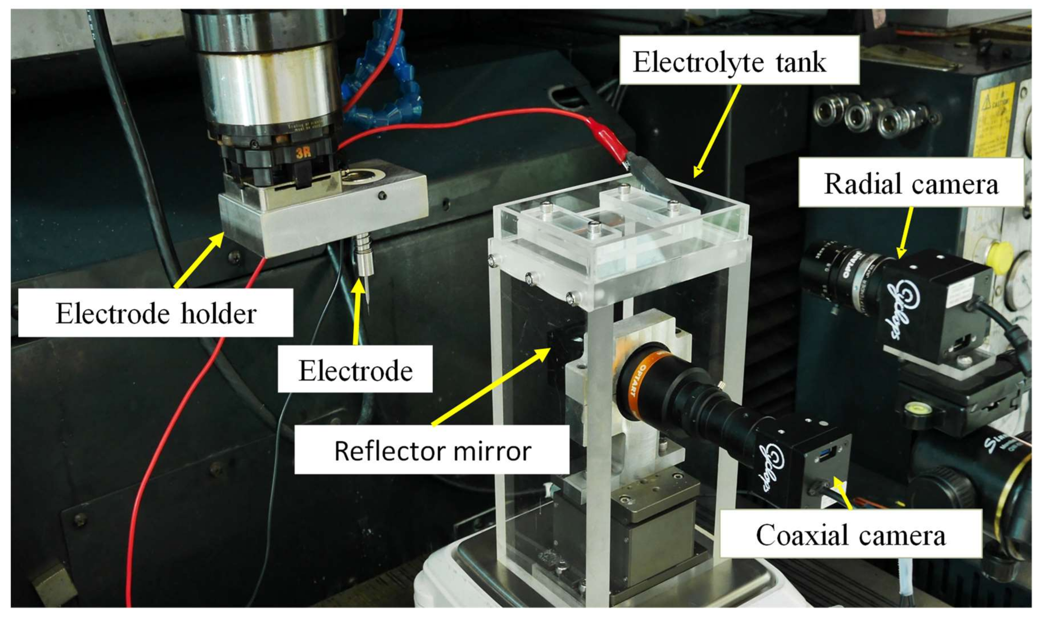
2. Experimental Setup and Method
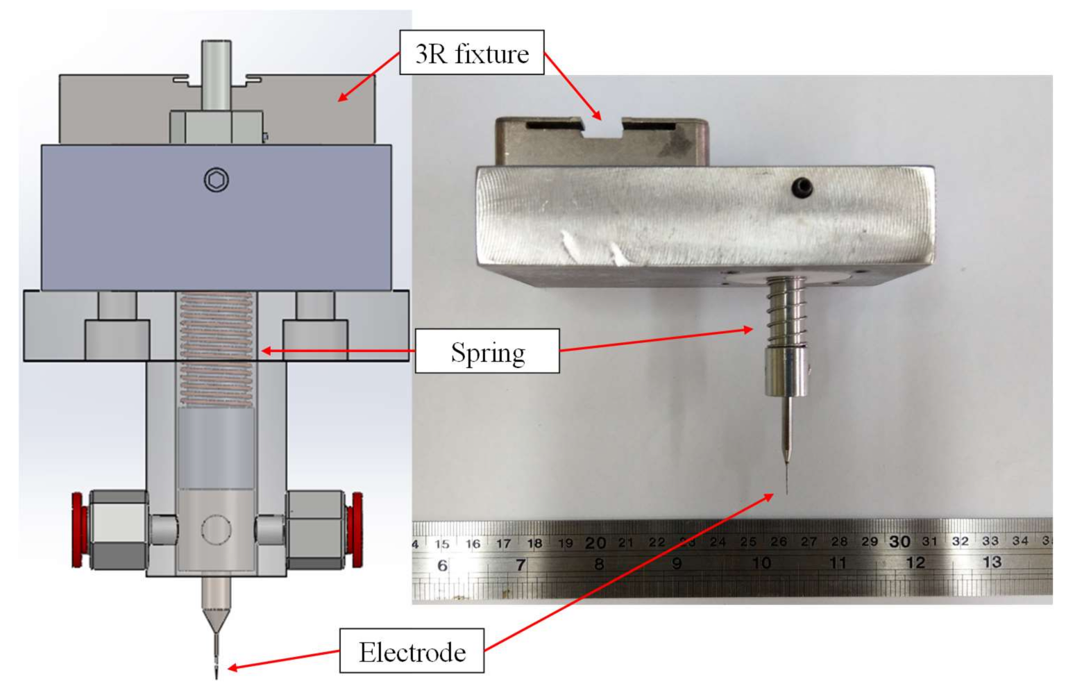
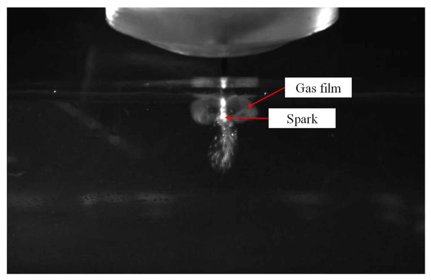
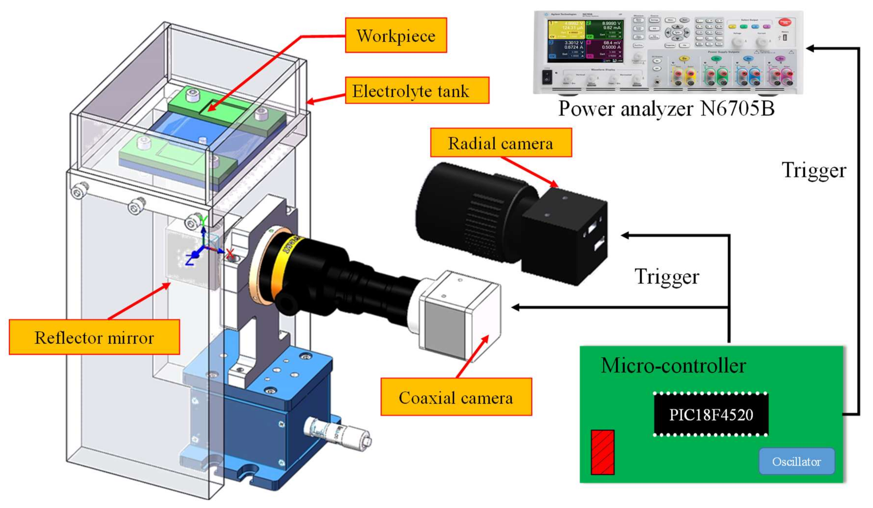
2.1. Setup
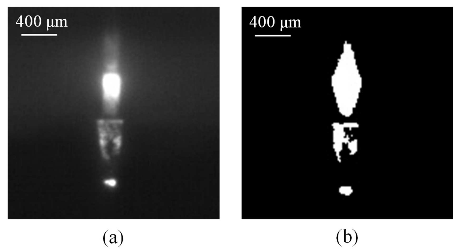
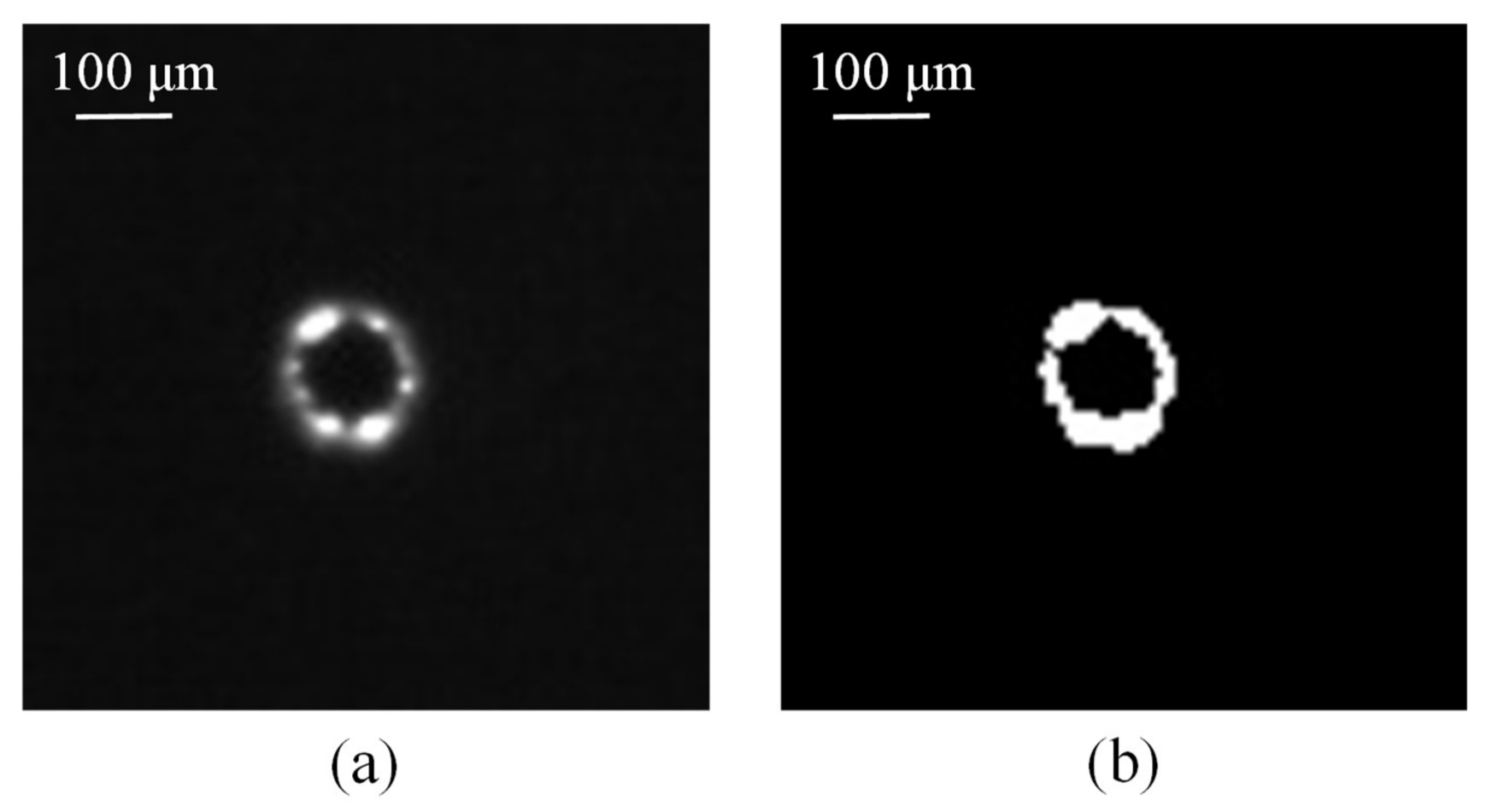
2.2. Estimation Method
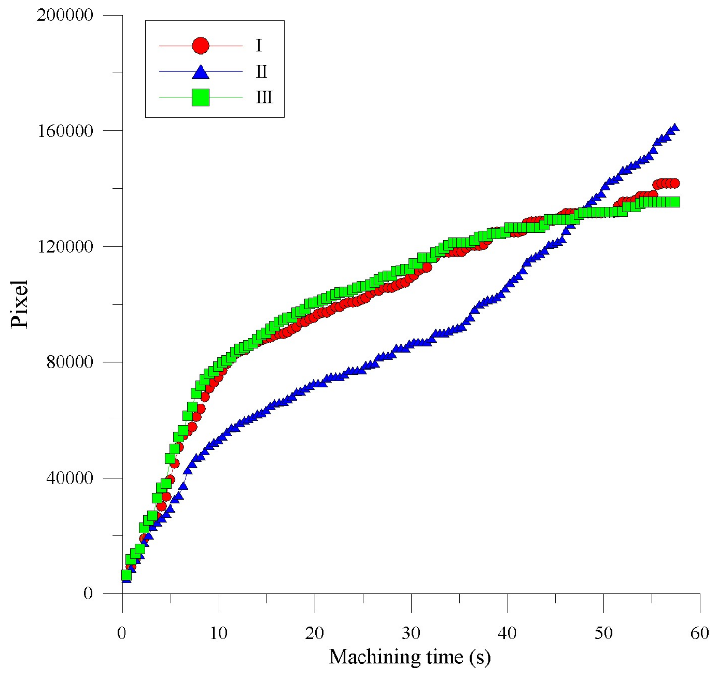
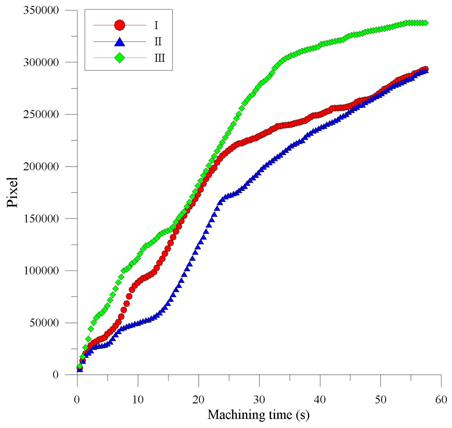
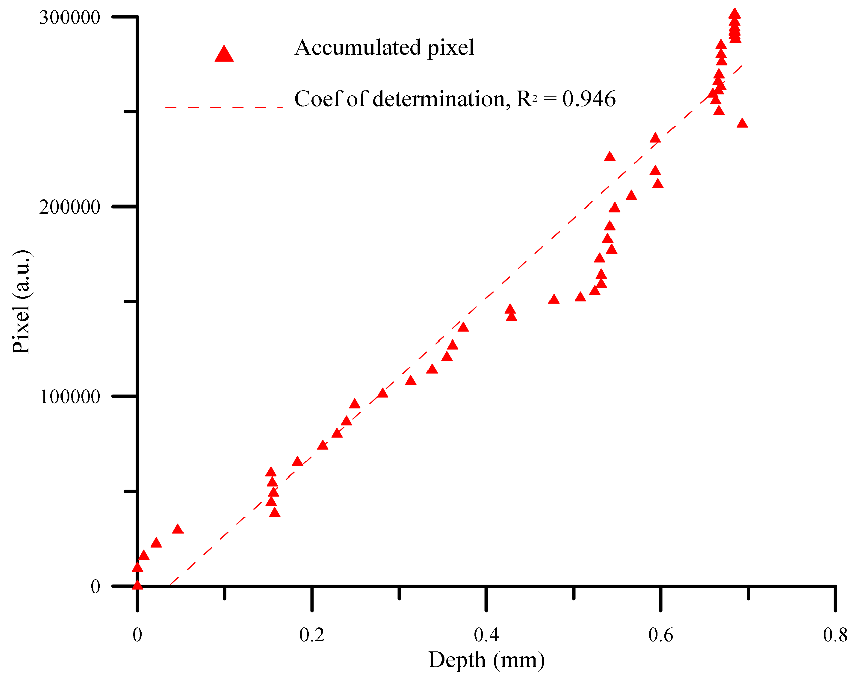
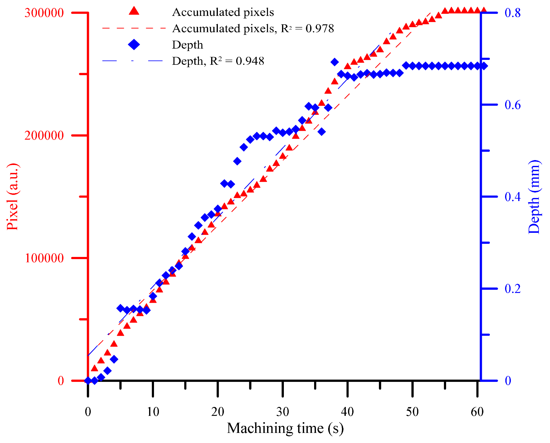
3. Results and Discussion
4. Conclusions
Acknowledgments
Author Contributions
Conflicts of Interest
References
- Díaz-Tena, E.; Rodríguez-Ezquerro, A.; de Lacalle Marcaide, L.L.; Bustinduy, L.G.; Sáenz, A.E. A sustainable process for material removal on pure copper by use of extremophile bacteria. J. Clean. Prod. 2014, 84, 752–760. [Google Scholar] [CrossRef]
- Díaz-Tena, E.; Rojo, N.; Gurtubay, L.; Rodríguez-Ezquerro, A.; López de Lacalle, L.N.; Oyanguren, I.; Barbero, F.; Elías, A. Biomachining: Preservation of acidithiobacillus ferrooxidans and treatment of the liquid residue. Eng. Life Sci. 2017, 17, 382–391. [Google Scholar] [CrossRef]
- Díaz-Tena, E.; Barona, A.; Gallastegui, G.; Rodríguez, A.; López de Lacalle, L.N.; Elías, A. Biomachining: Metal etching via microorganisms. Crit. Rev. Biotechnol. 2017, 37, 323–332. [Google Scholar] [CrossRef] [PubMed]
- Wüthrich, R.; Fascio, V. Machining of non-conducting materials using electrochemical discharge phenomenon—An overview. Int. J. Mach. Tools Manuf. 2005, 45, 1095–1108. [Google Scholar] [CrossRef]
- Wuthrich, R.; Ziki, J.D.A. Micromachining Using Electrochemical Discharge Phenomenon: Fundamentals and Application of Spark Assisted Chemical Engraving; William Andrew: New York, NY, USA, 2014. [Google Scholar]
- Pachaury, Y.; Tandon, P. An overview of electric discharge machining of ceramics and ceramic based composites. J. Manuf. Process. 2017, 25, 369–390. [Google Scholar] [CrossRef]
- Zheng, Z.-P.; Su, H.-C.; Huang, F.-Y.; Yan, B.-H. The tool geometrical shape and pulse-off time of pulse voltage effects in a Pyrex glass electrochemical discharge microdrilling process. J. Micromech. Microeng. 2007, 17, 265. [Google Scholar] [CrossRef]
- Cheng, C.-P.; Wu, K.-L.; Mai, C.-C.; Yang, C.-K.; Hsu, Y.-S.; Yan, B.-H. Study of gas film quality in electrochemical discharge machining. Int. J. Mach. Tools Manuf. 2010, 50, 689–697. [Google Scholar] [CrossRef]
- Jiang, B.; Lan, S.; Ni, J.; Zhang, Z. Experimental investigation of spark generation in electrochemical discharge machining of non-conducting materials. J. Mater. Process. Technol. 2014, 214, 892–898. [Google Scholar] [CrossRef]
- Goud, M.; Sharma, A.K.; Jawalkar, C. A review on material removal mechanism in electrochemical discharge machining (ECDM) and possibilities to enhance the material removal rate. Precis. Eng. 2016, 45, 1–17. [Google Scholar] [CrossRef]
- Giandomenico, N.; Meylan, O. Development of a new generator for electrochemical micro-machining. Procedia CIRP 2016, 42, 804–808. [Google Scholar] [CrossRef]
- Huang, S.F.; Zhu, D.; Zeng, Y.B.; Wang, W.; Liu, Y. Micro-hole machined by electrochemical discharge machining (ECDM) with high speed rotating cathode. Adv. Mater. Res. 2011, 295, 1794–1799. [Google Scholar] [CrossRef]
- Laio, Y.; Wu, L.; Peng, W. A study to improve drilling quality of electrochemical discharge machining (ECDM) process. Procedia CIRP 2013, 6, 609–614. [Google Scholar] [CrossRef]
- Kulkarni, A.; Sharan, R.; Lal, G. Measurement of temperature transients in the electrochemical discharge machining process. AIP Conf. Proc. 2003, 684, 1069–1074. [Google Scholar]
- Rajurkar, K.; Yu, Z. 3d micro-edm using cad/cam. CIRP Ann.-Manuf. Technol. 2000, 49, 127–130. [Google Scholar] [CrossRef]
- Ayesta, I.; Izquierdo, B.; Sanchez, J.; Ramos, J.; Plaza, S.; Pombo, I.; Ortega, N. Electrode path generation algorithm for complex shape cavities. Electrode design and application for blisk machining. In Proceedings of the 5th Manufacturing Engineering Society International Conference, Zaragoza, Spain, 26–28 June 2013. [Google Scholar]
- Flaño, O.; Ayesta, I.; Izquierdo, B.; Sánchez, J.; Zhao, Y.; Kunieda, M. Improvement of EDM performance in high-aspect ratio slot machining using multi-holed electrodes. Precis. Eng. 2018, 51, 223–231. [Google Scholar] [CrossRef]
- Wüthrich, R.; Spaelter, U.; Bleuler, H. The current signal in spark-assisted chemical engraving (SACE): What does it tell us? J. Micromech. Microeng. 2006, 16, 779. [Google Scholar] [CrossRef]
- Tang, W.; Kang, X.; Zhao, W. Enhancement of electrochemical discharge machining accuracy and surface integrity using side-insulated tool electrode with diamond coating. J. Micromech. Microeng. 2017, 27, 065013. [Google Scholar] [CrossRef]
- Han, M.-S.; Min, B.-K.; Lee, S.J. Modeling gas film formation in electrochemical discharge machining processes using a side-insulated electrode. J. Micromech. Microeng. 2008, 18, 045019. [Google Scholar] [CrossRef]
- Wüthrich, R.; Hof, L.A.; Lal, A.; Fujisaki, K.; Bleuler, H.; Mandin, P.; Picard, G. Physical principles and miniaturization of spark assisted chemical engraving (SACE). J. Micromech. Microeng. 2005, 15, S268. [Google Scholar] [CrossRef]


| Parameter | Value |
|---|---|
| Voltage | 40 V |
| Peak current | 1.5 A |
| Workpiece material | Quartz glass |
| Thickness of workpiece | 10 mm |
| Tool electrode material | Tungsten carbide |
| Electrolyte | KOH |
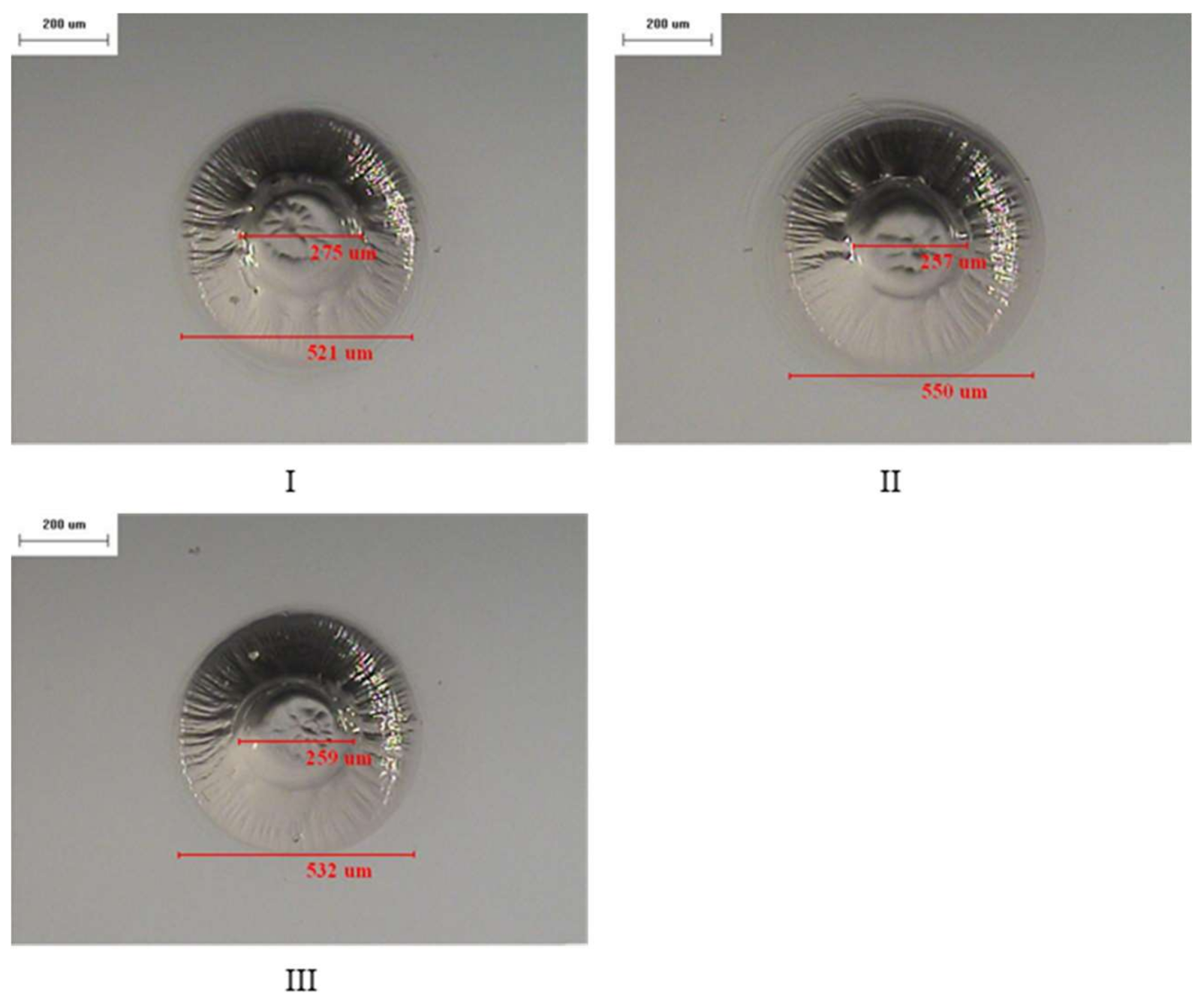
| Experimental Dataset | Hole Diameter (μm) | Heat Affected Diameter (μm) |
|---|---|---|
| I | 275 | 521 |
| II | 257 | 550 |
| III | 259 | 532 |
© 2018 by the authors. Licensee MDPI, Basel, Switzerland. This article is an open access article distributed under the terms and conditions of the Creative Commons Attribution (CC BY) license (http://creativecommons.org/licenses/by/4.0/).
Share and Cite
Ho, C.-C.; Wu, D.-S. Characteristics of the Arcing Plasma Formation Effect in Spark-Assisted Chemical Engraving of Glass, Based on Machine Vision. Materials 2018, 11, 470. https://doi.org/10.3390/ma11040470
Ho C-C, Wu D-S. Characteristics of the Arcing Plasma Formation Effect in Spark-Assisted Chemical Engraving of Glass, Based on Machine Vision. Materials. 2018; 11(4):470. https://doi.org/10.3390/ma11040470
Chicago/Turabian StyleHo, Chao-Ching, and Dung-Sheng Wu. 2018. "Characteristics of the Arcing Plasma Formation Effect in Spark-Assisted Chemical Engraving of Glass, Based on Machine Vision" Materials 11, no. 4: 470. https://doi.org/10.3390/ma11040470
APA StyleHo, C.-C., & Wu, D.-S. (2018). Characteristics of the Arcing Plasma Formation Effect in Spark-Assisted Chemical Engraving of Glass, Based on Machine Vision. Materials, 11(4), 470. https://doi.org/10.3390/ma11040470