Article

3D Printability of Alginate-Carboxymethyl Cellulose Hydrogel

1
Industrial and Manufacturing Engineering Department, North Dakota State University, Fargo, ND 58102, USA
2
Pharmaceutical Sciences Department, North Dakota State University, Fargo, ND 58102, USA
*
Author to whom correspondence should be addressed.
Materials 2018, 11(3), 454; https://doi.org/10.3390/ma11030454
Submission received: 3 February 2018 / Revised: 7 March 2018 / Accepted: 8 March 2018 / Published: 20 March 2018
(This article belongs to the Special Issue NextGen Materials for 3D Printing)

Abstract

:
Three-dimensional (3D) bio-printing is a revolutionary technology to reproduce a 3D functional living tissue scaffold in-vitro through controlled layer-by-layer deposition of biomaterials along with high precision positioning of cells. Due to its bio-compatibility, natural hydrogels are commonly considered as the scaffold material. However, the mechanical integrity of a hydrogel material, especially in 3D scaffold architecture, is an issue. In this research, a novel hybrid hydrogel, that is, sodium alginate with carboxymethyl cellulose (CMC) is developed and systematic quantitative characterization tests are conducted to validate its printability, shape fidelity and cell viability. The outcome of the rheological and mechanical test, filament collapse and fusion test demonstrate the favorable shape fidelity. Three-dimensional scaffold structures are fabricated with the pancreatic cancer cell, BxPC3 and the 86% cell viability is recorded after 23 days. This hybrid hydrogel can be a potential biomaterial in 3D bioprinting process and the outlined characterization techniques open an avenue directing reproducible printability and shape fidelity.

1. Introduction

Bio-printing is a revolutionary technology uses a computer-controlled 3D printing discipline to reproduce a 3D functional living tissue scaffold through controlled layer-by-layer deposition of biomaterials along with high precision positioning of cells [1,2,3,4]. A scaffold is a highly porous 3D construct that serves as a temporary structural support for growing the isolated cells, providing nutrient to new tissues, facilitating the healing process, restoring the tissue function and minimizing the wound scar [5,6,7,8,9,10]. Traditionally, a preformed solid biodegradable polymeric scaffold fabricated by casting, specifically leaching, gas forming, phase separation, melt molding, freeze drying [11,12] and electrospinning [13] is seeded with a cell suspension in tissue engineering. However, these techniques allow minimum control over pore size, scaffold geometry, interconnectivity and spatial distribution. Hence, less biomimicry is achieved [14].
To regenerate the tissue, the fabricated scaffold should support certain criteria, such as facilitating cell migration, proliferation and differentiation, removal of the waste component and finally stimulating vascularization [15,16]. Designing the scaffold architecture especially with porosity has a positive impact on cell survivability, proliferation and migration [17,18,19,20,21]. In terms of viability, the porous cell-laden scaffold shows almost 30% more viability than non-porous scaffold [22]. The porosity in scaffold facilitates the cell attachment, migration, differentiation, proliferation and extracellular matrix (ECM) production [23,24,25,26]. Therefore, the 3D scaffold architecture should be designed addressing the tissue-specific structural, mechanical and biological constraints [27,28,29].
3D bio-printing processes provide spatial control and repeatability of material deposition for attaining the design specific tissue scaffold in 3D. Three common bioprinting strategies [4] such as inkjet bioprinting [30,31], electro-hydrodynamic jetting [32,33,34,35], extrusion-based bioprinting [36,37] and laser-assisted bioprinting [38,39,40] are used to fabricate the 3D tissue scaffolds. Among them, the extrusion-based system is compatible with a diverse range of materials printing including hydrogels, biocompatible copolymers and their composition including heterogeneous bio-ink and cell spheroid [41]. Building tissue construct with cell-laden bio-ink is recently reported [42,43]. However, low extrusion pressure needs to be applied on cell-laden bio-ink to increase the cell viability [44]. A wide range of biomaterials, viscosity range from 30 mPa/s to 6 × 10⁷ mPa/s is suitable for simpler drive-control pneumatic extrusion system [45]. However, mechanical dispensing system that is, screw extruder can deliver material with higher viscosity.
Even though the actuation accuracy of extrusion based fabrication system is in micron level, the shape fidelity of the printed scaffold structure is still a challenge. Thus, identifying appropriate biomaterials to fabricate the 3D controlled porous structure using bio-AM to ensure shape fidelity and mechanical integrity is an active area of research. A number of characteristics, that is, biocompatibility, printability, degradation kinetics and byproducts should be considered before selecting biomaterials for scaffold fabrication [1]. Various types of natural hydrogel, that is, sodium alginate, gelatin, chitosan, collagen, fibrin [46] and synthetic polymers, that is, polycaprolactone (PCL), polyethylene glycol (PEG) and polylactic acid (PLA), are used as biomaterials during scaffold fabrication [47]. During and after the scaffold fabrication, it serves as a synthetic extracellular matrix (ECM) and creates cell-friendly 3D micro-environment to support the encapsulated cells [48]. Due to the containment of adjustable physical and chemical properties, hydrogels become one of the major candidates in tissue repair and drug delivery [49]. Moreover, the micro-environment having higher water content makes hydrogel especially attractive for cell delivery and encapsulation [50]. Therefore, cell encapsulation into the hydrogels is a favorable method towards overcoming the challenges of providing high cell density, achieving uniform cell distribution and ensuring suitable microenvironment for the cell.
Sodium alginate is a seaweed-extracted naturally derived polysaccharide, has been used in 3D bio-printing for several years because of its good biocompatibility. The inclusion of calcium ions directs cross-linking of the carboxylate groups of sodium alginate to achieve excellent gelation without hampering biocompatible environment [51]. Various cell types such as fibroblast [52], myoblast, endothelial [53], chondrocytes [54] and schwann [55] have been encapsulated into alginate for small scale culturing. The dissipation of Ca2+ ions in physiological conditions results in water-soluble, nontoxic alginate and eventually the gradual degradation of Ca-alginate gel [56]. However, achieving the intricate internal porous architecture with predefined shape, size and dimensional integrity using hydrogels material is limited. The viscosity of the hydrogel material becomes a conflicting characteristic to achieve its functionality. For example, the lower viscous hydrogel precursor, that is, less than 300 cps limits the mechanically stable structure [57]. Whereas increasing the viscosity of the hydrogel (≤100,000 cps) will bring the mechanical integrity but reduces the cell viability and proliferation [58].
To fabricate scaffold with accurate pore size and geometry, other biomaterials are often mixed with alginate to prepare a hybrid hydrogel. The hybrid hydrogel enables to achieve physical gelation characteristics and solidified filament morphology after extrusion to support the successive layers. Besides, improved cell activities and cell-friendly microenvironment that is, proliferation, migration and differentiation has been reported with hybrid hydrogel [59]. A clay-based bio-ink composed of laponite nano-clay, alginate and methylcellulose have been developed demonstrating the printability and cell viability [60]. PLA nano-fiber is mixed with alginate to fabricate knee meniscus with hASC [61]. The result shows better cell proliferation and ECM production in the hybrid filament than a pure alginate filament. In another work, methylcellulose was used with alginate to fabricate clinically relevant scaffold and the result was comparable with pure alginate scaffold [62]. Methylcellulose gives better gelation and mechanical properties to achieve clinically relevant scaffold. Gelatin has been used with alginate in several reported works. The ratio of alginate and gelatin concentration is optimized for better printability and good cell survivability [59]. The effects of various process parameters, that is, air pressure, feed rate, printing distance on the shape fidelity of the structure as well as cell survivability has been illustrated [57]. In this work, the combination of alginate and gelatin has been used as hydrogel materials. Comparison of characteristics between alginate and alginate-gelatin hydrogel in term of cell spreading, adhesion, viability has been reported where alginate-gelatin hybrid hydrogel shows comparable results [63]. A bio-ink composed of alginate and nano-cellulose named CELLINK is commercially available which presents shear-thinning and fast crosslinking features [64]. To improve the rheological properties graphene oxide (GO) is added with alginate which shows better shape fidelity through increased in hydrogen bonding [65]. A composite hydrogel including the different percentage of alginate, gelatin and hydroxyapatite has been used to demonstrate the applicability in the regeneration of bone tissue [66]. Polycaprolactone (PCL) is also combined with alginate to improve the mechanical strength of the fabricated scaffold expecting the improved functionality in bone tissue structure [67].
Carboxymethylcellulose (CMC) is a high-molecular-weight water-soluble polysaccharide used for viscosity modifier or thickener. It has been reported that the binding of CMC’s matrix protein assists in cell migration and cell attachment [68]. Moreover, alginate-CMC (Alg-CMC) hybrid hydrogel has been used to fabricate beads for various drug delivery experiments [69,70]. However, to our best knowledge, the combination of alg-CMC has not been explored for 3D bio-printing which is examined in this manuscript. The extrusion-based in-house bio-printing system is used to fabricate 3D scaffold structures with special features. Dispensing material used in this technique requires a suitable viscosity and density as well as the shape fidelity retaining capability and high cell viability during and after printing [71]. A set of systematic quantitative characterization tests such as rheological and mechanical test, filament collapse and 2D fusion test with variational pore size, the effects of air pressure and print distance on filament width are conducted to validate its printability, shape fidelity. Afterwards, 3D scaffold structures are fabricated with the pancreatic cancer cell, BxPC3 and the cell viability is recorded. The outcome of all experiments conducted and cell viability measurement imprints that this hybrid hydrogel is a favorable biomaterial for 3D bioprinting process.

2. Material and Method

2.1. Preparation of Hydrogels

The bio-materials used for scaffold fabrication are alginate (alginic acid sodium salt from brown algae; Sigma-Aldrich, St. Louis, MO, USA) and carboxymethyl cellulose (CMC) (Sigma-Aldrich). The chemical structures of the two materials are shown in Figure 1a,b respectively. Alginate is a common biopolymer, composed of (1-4)-linked β-Dmannuronic (M) and α-Lguluronic acids (G) as shown in Figure 1a. This material is a negatively charged linear copolymer (M and G blocks) which is soluble in the water and supports cell growth and exhibits high biocompatibility. The G-block of this material assists to form gels and GM and M blocks improve the flexibility.
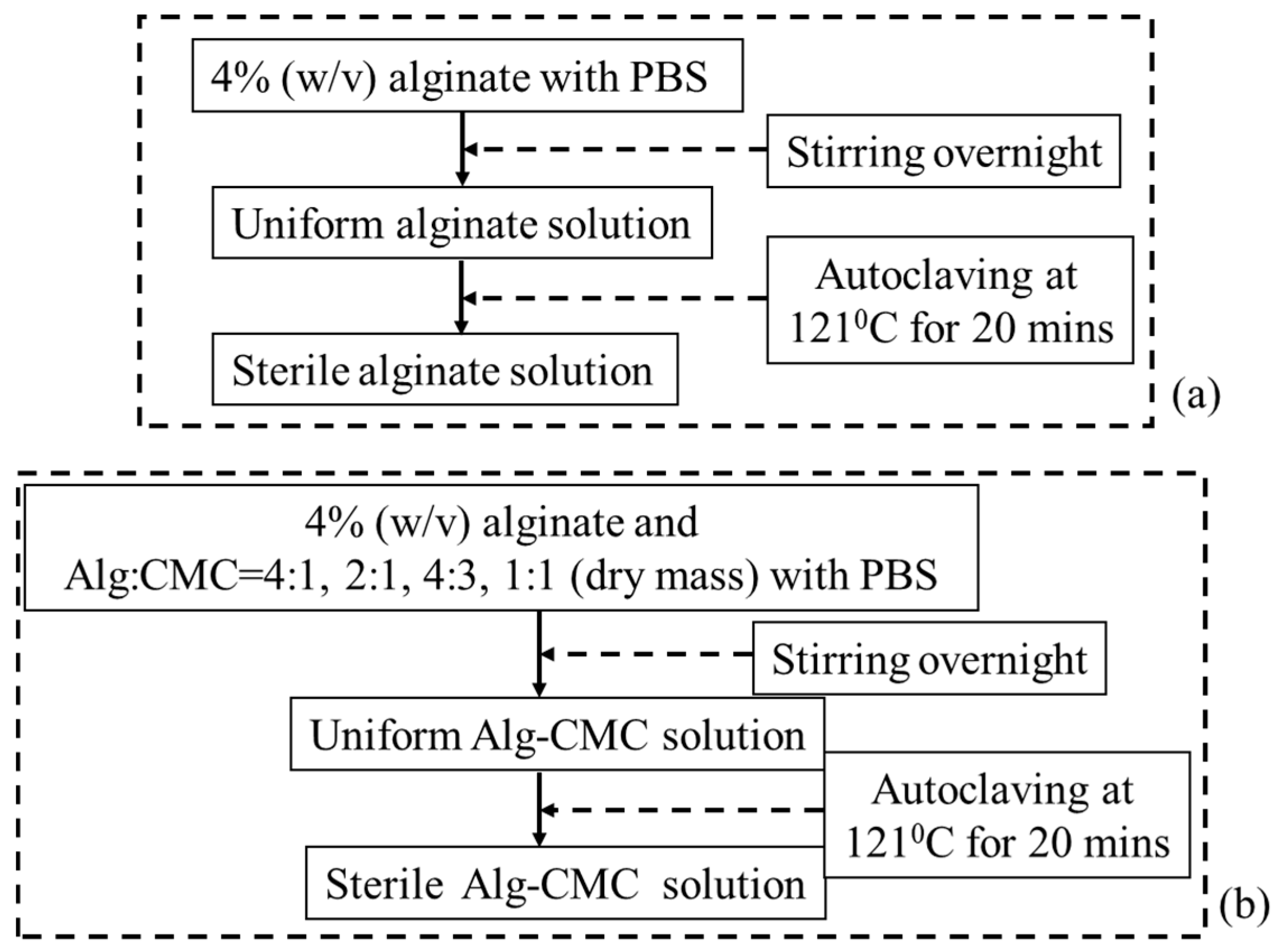
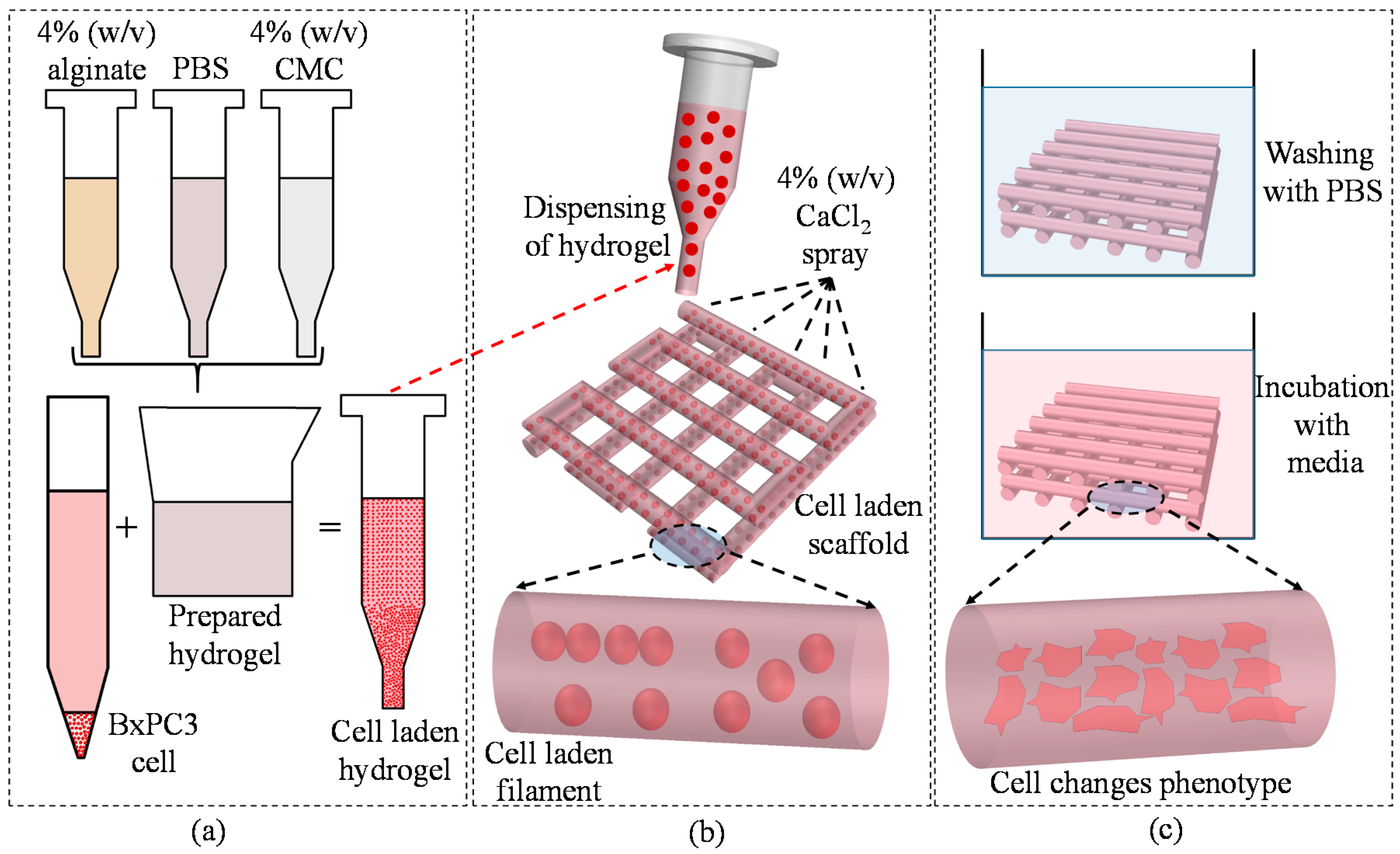
Carboxymethylcellulose (CMC) is an anionic water-soluble biopolymer derived naturally or through chemical reaction from cellulose. It is a copolymer of β-d-glucose and β-d-glucopyranose-2-O-(carboxymethyl)-monossdium salt which are connected via β-1,4-glucosidic bonds [72]. This material is non-toxic and non-allergenic, is widely used as thickener [73]. Each glucose monomer has three hydroxyl groups which can be substituted by a carboxyl group. More substitution of the hydroxyl group by carboxyl makes the cellulose more soluble, thicken and stable [72]. A pure alginate and mixture of alginate and carboxymethyl cellulose (Alg-CMC) solutions are prepared following the steps are shown in Figure 2.
Since both alginate and CMC are polar solute, they are soluble in water. These two materials make intermolecular action through the formation of hydrogen bonds and consequently compatible blended hybrid hydrogel. 4% (w/v) CaCl2 (Sigma-Aldrich) is prepared with 0.2 μm filtered deionized (DI) water and used as chemical cross-linker. The extrusion-based bio-printing system needs fast gelation. Since, alginate contains carboxyl group (–COO–), this part of the hybrid hydrogel is cross-linked with the application of divalent cation, for example, Ca2+. Ca2+ generates ionic inter-chain bridges with G and M blocks and assists to achieve fast gelation. CMC also contains carboxyl group (–COO–) which forms calcium complex with the presence of Ca2+. Hence, this hybrid hydrogel aids the fast formation of gel during fabrication and encapsulates the cells. Moreover, mixing CMC with alginate will increase the solution viscosity which will improve the printability.

2.2. Cell Culture

BxPC3, the human pancreatic cancer cells are cultured and maintained in high glucose DMEM, 2 mM Glutamine and 10% Fetal Bovine Serum (FBS) with 100 µg/mL penicillin and 100 µg/mL streptomycin (Sigma-Aldrich) in 5% CO2 at 37 °C incubator. The culture medium is changed twice a week. Cells at passage 5 are used for 3D bio-printing.

2.3. Rheological Test for Hydrogel

Rheological properties by 4% (w/v) alginate and various composition of Alg-CMC (n = 3) have been determined at room temperature using a Brookfield (DV-II+Pro) rotational viscometer (Middleboro, MA, USA). The shear rate, shear stress, viscosity and percentage of torque have been measured at various rotational rpm.

2.4. Mechanical Test for Hydrogel

The Young’s modulus of the specimens is determined using the Nano-indentation equipment. Indentation is recorded at six random spots (n = 6) during each run of the experiment. Measurements are carried out at room temperature with an Atomic Force Microscopy, that is, AFM (Dimension 3100, Veeco, Town of Oyster Bay, NY, USA. The indenter used in this test is a rectangular 0.01–0.025 Ωcm Anatomy (n) doped Si tip (RTESPA-300, Bruker, Billerica, MA, USA). The resonance frequency and an average spring constant of the indenter are about 300 kHz and 40 N/m respectively. The radius of curvature at the tip is nominally 8 nm and tip half angle is 20°. The test indentation on sapphire (Bruker, Billerica, MA, USA) determines the deflection sensitivity of the indenter. Once Young’s modulus is determined, the reduced modulus is calculated using the following equation:
1 E r = 1 ν 2 E + 1 ν i 2 E i
where Er is reduced modulus, Ei = 150 GPa and ν i = 0.17 is Poisson’s ratio of the probe respectively, E and ν are Young’s modulus and Poisson’s ratio of the sample. The Poisson’s ratio of the sample is considered as ν = 0.5 .

2.5. Scanning Electron Microscope

The microstructure of fabricated scaffold is analyzed by scanning electron microscopy (JEOL, JSM-6010LA, analytical Scanning electron microscope, Tokyo, Japan). The accelerating voltage, spot size (SS) and working distance (WD) used in this imaging are 10 kV, 50 mm and 13–14 mm respectively with magnifications of ×27, ×130, ×160, ×180, ×700 scale. The samples have been washed three times with PBS containing Ca2+ and Mg2+ and dehydrated using a gradation series of ethanol/distilled water solutions.

2.6. Cell-Free Scaffold Fabrication

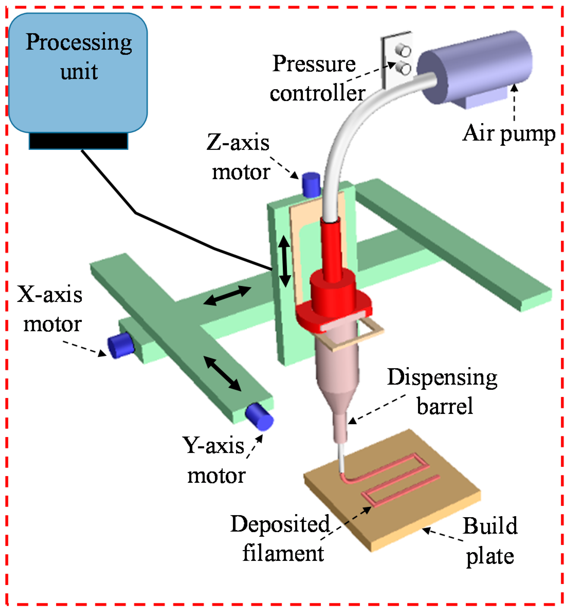
A three-axis in-house built 3D bio-printer is used to fabricate the acellular and cell-laden scaffold under sterile condition. The hydrogel is stored in a disposable barrel reservoir (EFD, Nordson, Westlake, OH, USA) and dispensed pneumatically through a dosing nozzle (EFD, Nordson, the inner diameter 410 µm) on a stationary print bed as shown in Figure 3. The hydrogel flow rate and width of filament are controlled by dispensing pressure, nozzle speed and print distance (i.e., the distance from the nozzle tip to build plane). The vectorized tool-path of the scaffold is programmed and converted into the machine-readable language with a visual basic based scripting language. The scaffold is fabricated layer-upon-layer where the hydrogel filaments of succeeding layer are deposited in a 0°/90° fashion into petri-dish. The spray of CaCl2 ensures the chemical cross-linking of the fabricated scaffold. For various compositions of Alg-CMC (4:1; 2:1, 4:3 and 1:1), 1D line, 2D grid and 3D scaffolds are printed and the filament width and pore size are measured using ImageJ software unless and otherwise stated. For each data of filament width and pore size, three random measurements (n = 3) are taken from random locations and the data are represented as a mean ± standard deviation.

2.6.1. Filament Fusion Test

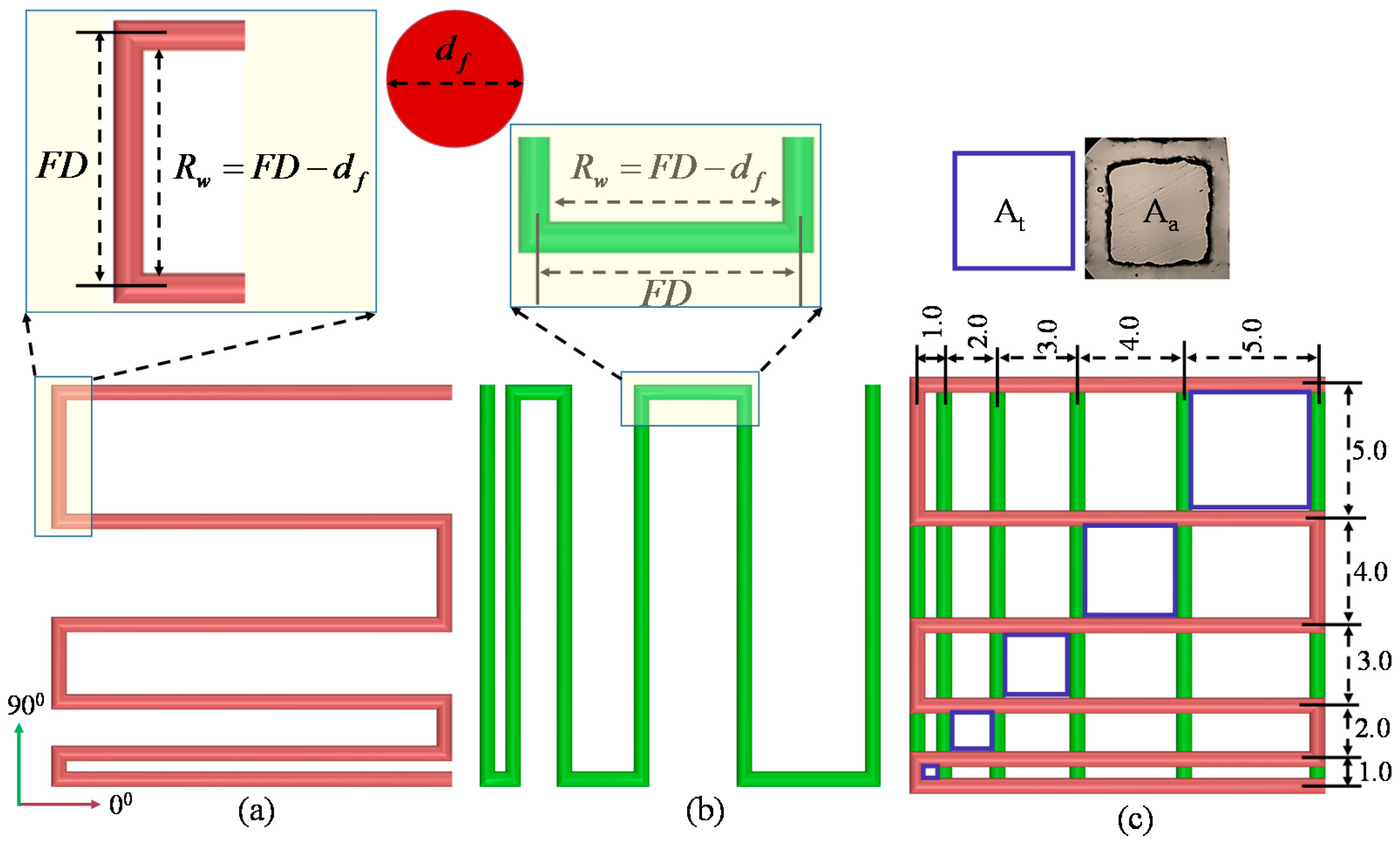
Four consecutive layers of various Alg-CMC compositions are fabricated layer-upon-layer without applying CaCl2 to conduct the filament fusion test. The fabricated scaffold follows 0°–90° pattern which captures the 2D effect and increasing filament to filament distance (FD). The range of filament to filament distance used here is 1–5 mm with 1 mm increments. After considering the filament diameter (df), the raster width is defined as, R w = F D d f as shown in Figure 4. To facilitate the visualization, each composition is mixed with different colors. To avoid the undesirable surface tension, measurement is recorded from two top layers. Air pressure, nozzle speed, nozzle diameter and print distance used in this test are respectively 8 psi, 5 mm/s, 0.41 mm and 0.7 mm. Pictures of fabricated scaffolds are taken with canon (EOS Rebel T6, Melville, NY, USA) high-resolution camera right after the fabrication to avoid the unwanted material spreading. Two different factors, that is, the percentage of diffusion rate (rate of material spreading) (Dfr) and printability (Pr) [59] are determined respectively using Equations (2) and (3) during filament fusion test shown below. The plotted values represent the 3 repetitions of measurements for each Alg-CMC composition.
D f r = A t A a A t × 100 %
P r = L 2 16 A c
where, At and Aa are a theoretical and actual areas of pore respectively, L is the perimeter of the pore. The diffusion rate of a pore without any material spreading is 0 (i.e., At = Aa) and for a perfect square pore, the printability is 1.0.

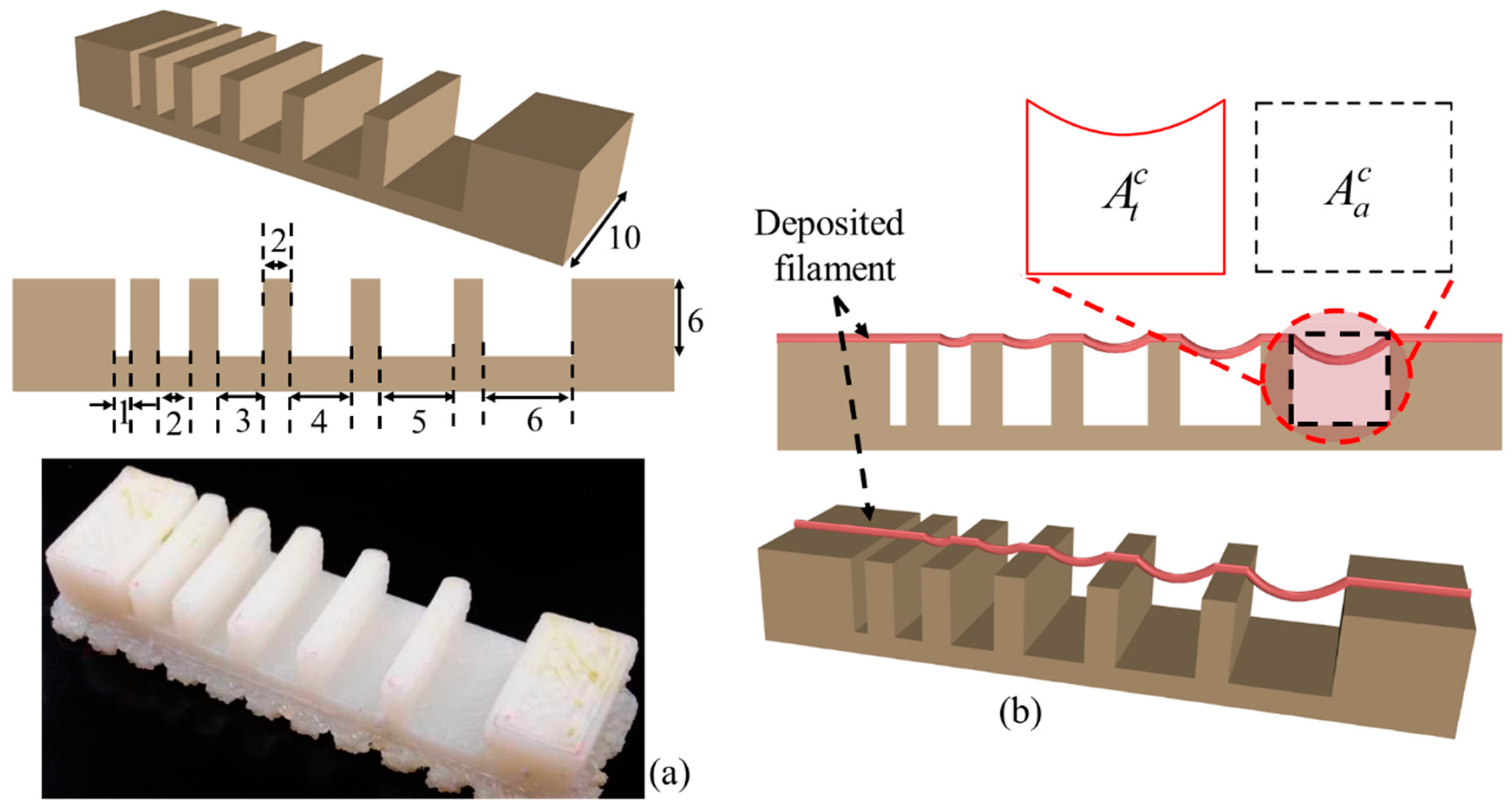
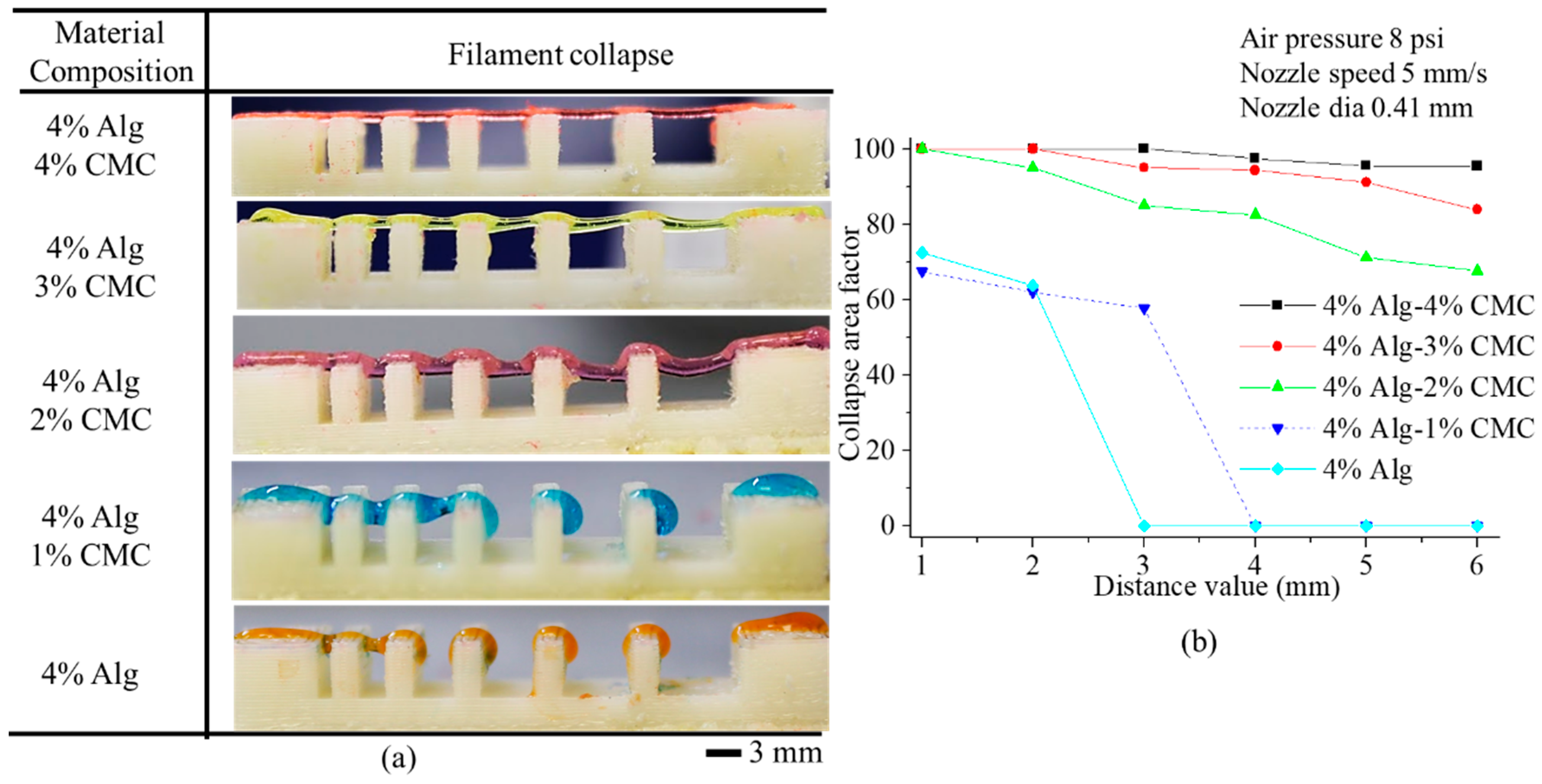
2.6.2. Filament Collapse Test

The filament collapse test is conducted following our prior work [74] and the work by Therriault et al. [75]. The mid-span deflection of a suspended filament is analyzed to determine the material collapse. A platform consisting of seven pillars with a known space of 1, 2, 3, 4, 5, 6 mm are modeled with a CAD software Rhino 5.0 as shown in Figure 5a. The dimension of five pillars situated in the middle is 2 × 10 × 6 mm3 and the dimension of the two corner pillars is 5 × 10 × 6 mm3. The platform is fabricated using “Dimension 1200es” 3D printer made by Stratasys with ABS material as shown in Figure 5a. A single filament of various compositions is deposited on this platform as shown in Figure 5b.
The picture of the deposited filament is taken with canon (EOS Rebel T6) high-resolution camera right after the suspension to avoid the unwanted material deflection. Air pressure, nozzle diameter and nozzle speed used for this test are respectively 8 psi, 5 mm/s and 0.41 mm. Collapse area factor (Cf), that is, the percentage of the actual area after deflecting the suspended filament with respect to the theoretical area is determined using the following equation:
C f = A a c A t c × 100 %
where, A a c and A t c are actual and theoretical area respectively as shown in Figure 5b. If the material is too viscous and unable to make a bridge between two pillars, the actual area is considered as zero and so as the collapse area factor. On the other hand, if filament does not collapse and makes a straight bridge between two consecutive pillars, then A a c = A t c and consequently the collapse area factor is 100%. The plotted values represent the 3 repetitions of measurements for each Alg-CMC composition.

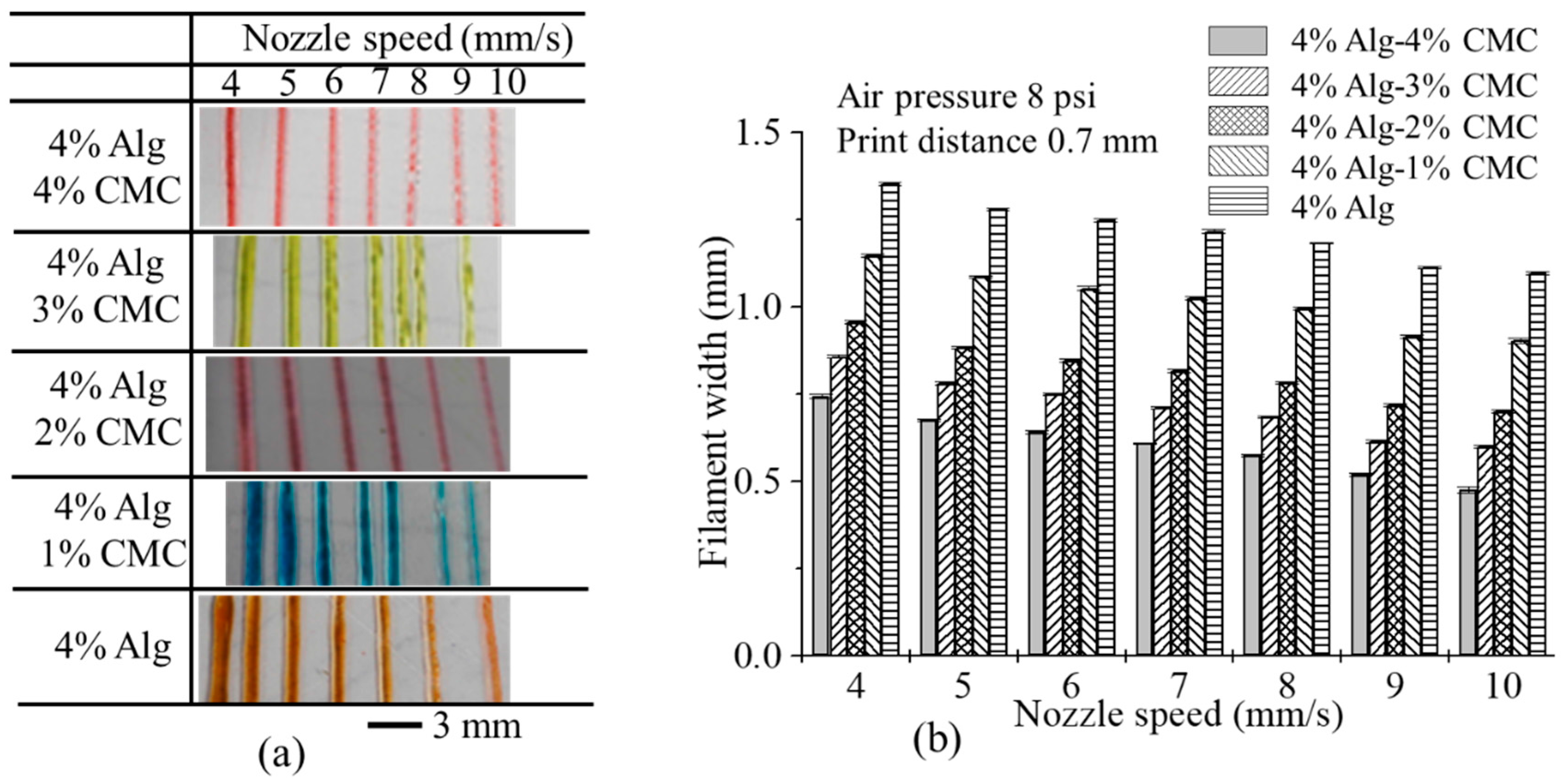
2.6.3. Effect of Nozzle Speed, Air Pressure and Print Distance on Filament Width

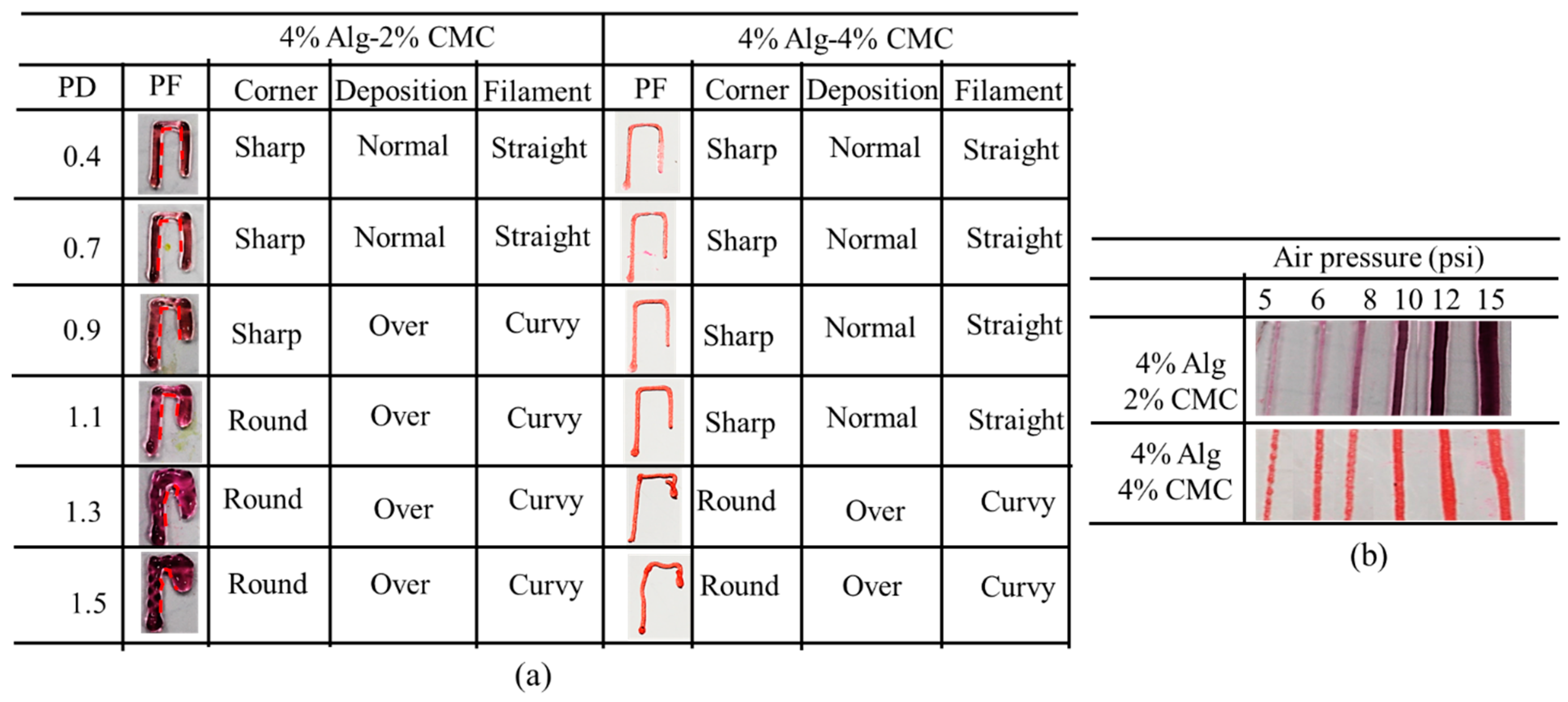
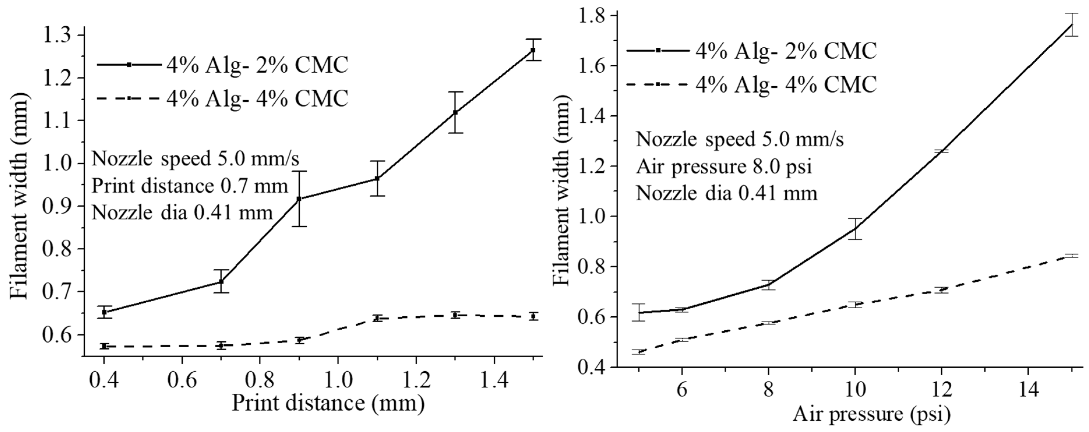
For each composition of the hydrogel, a line having 10 mm length is deposited (three layers) with various nozzle speed, that is, 4, 5, 6, 7, 8, 9, 10 mm/s. The air pressure and print distance used for this test are 8 psi and 0.7 mm respectively. To determine the effect of air pressure and print distance on filament width, a line having 10 mm length is deposited (three layers) with the material composition of 4% Alg-2% CMC and 4% Alg-4% CMC. Various air pressure, for example, 5, 6, 8, 10, 12 and 15 psi is used during inspecting the effect of air pressure. The nozzle speed, print distance are used for this test is 5 mm/s and 0.7 mm respectively. Various print distances, for example, 0.4, 0.7, 0.9, 1.1, 1.3 and 1.5 mm are used to demonstrate the effect of print distance on filament width. The nozzle speed and air pressure used for this test are 5 mm/s and 8 psi respectively. For all of these three tests, the nozzle diameter is used as 0.41 mm. The width of the filament is recorded with Zeiss bright field inverted microscope for each of this test. The plotted values represent the 3 repetitions of measurements.

2.6.4. Qualitative and Quantitative Test for Lateral Pore

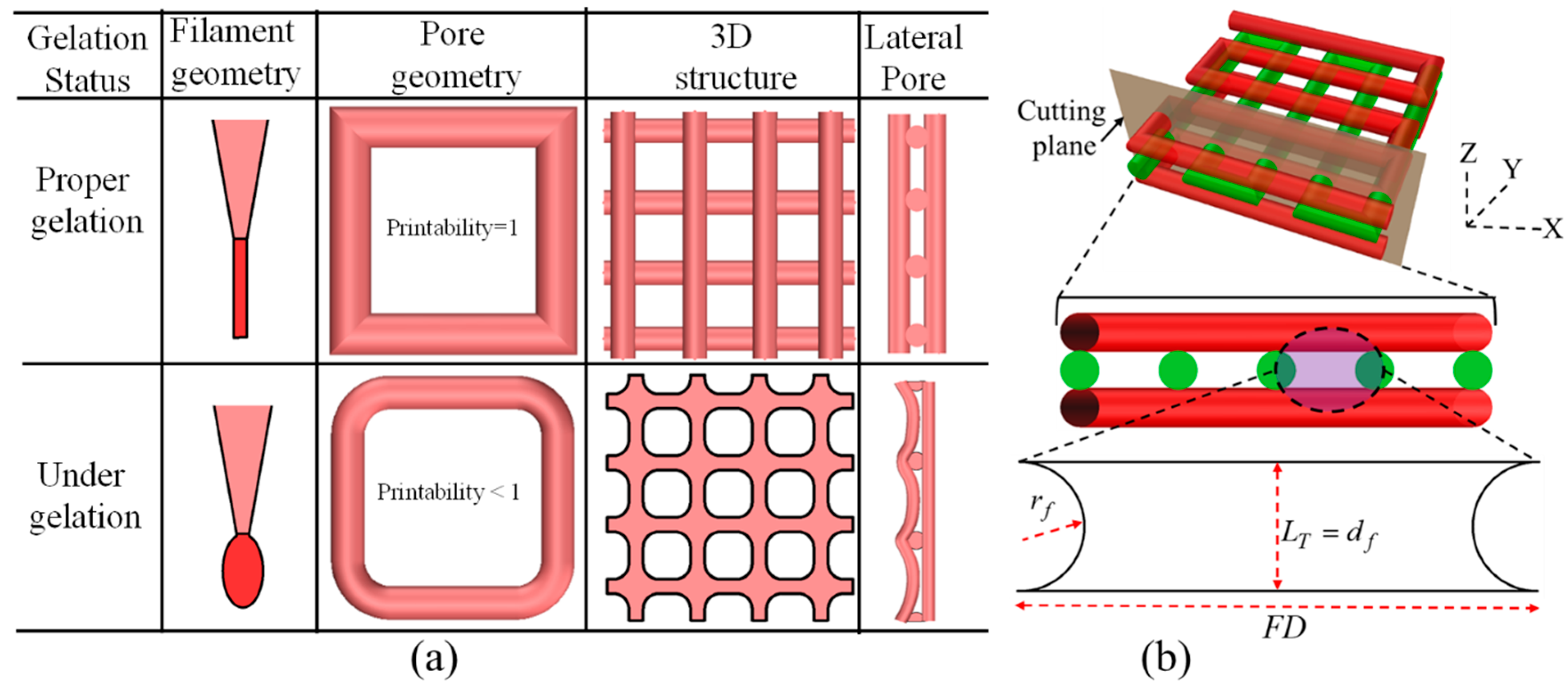
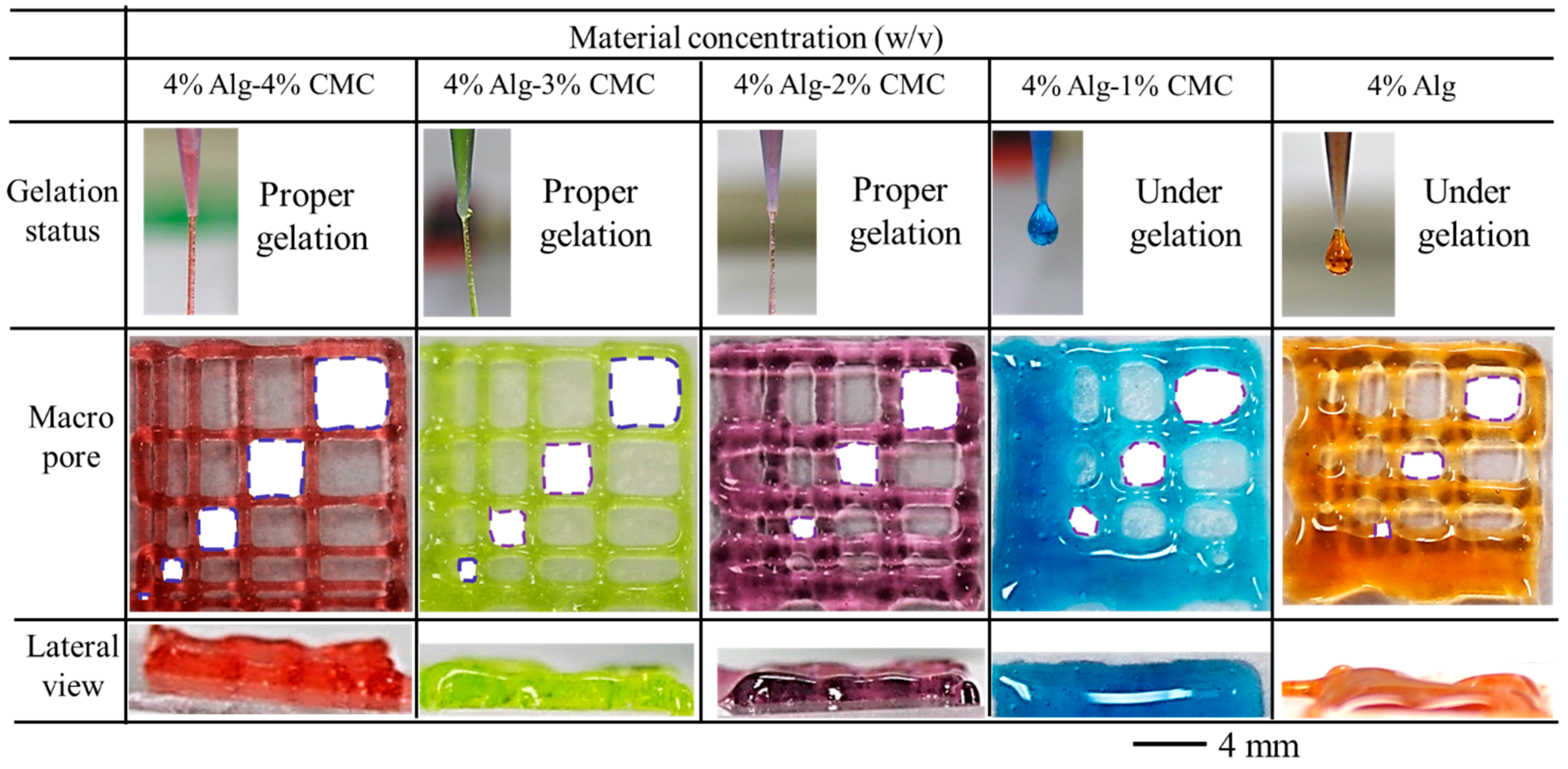
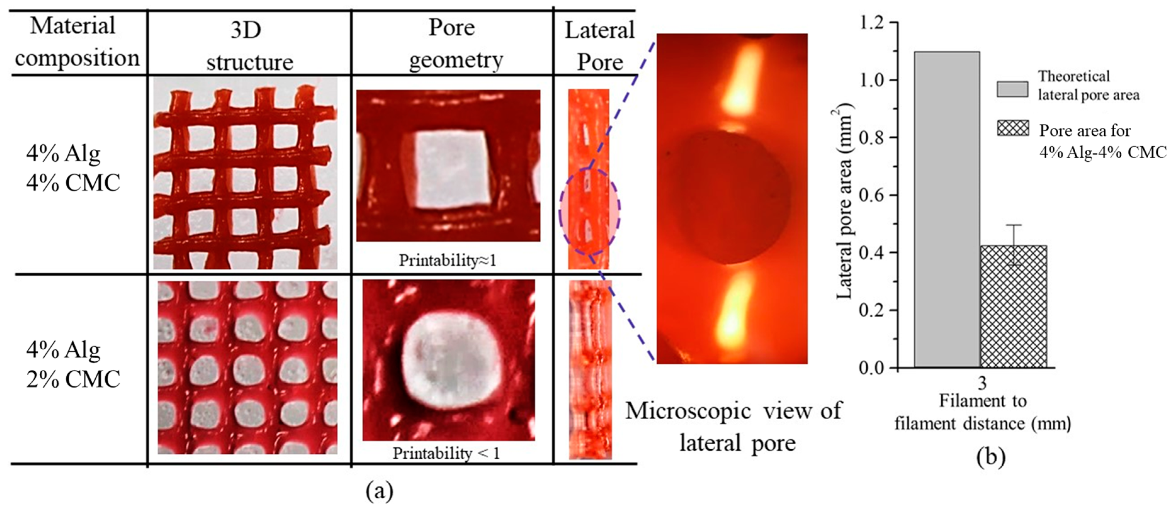
Two different qualitative tests are conducted during fabrication of scaffold. Firstly, each of the compositions is suspended in open air with an 8-psi air pressure and 10 mm print distance and observed if it makes continuous filament or just droplets. If any composition makes continuous filament, this is defined as proper gelation as shown in Figure 6a. The composition making proper gelation potentially may maintain the shape fidelity of the fabricated scaffold. On the other hand, the composition making droplet during suspension is defined as under-gelation as shown in Figure 6a which loses the shape fidelity during the progress of scaffold fabrication. Secondly, the lateral porosity of the fabricated scaffold with each of the compositions is visually observed to see the difference. Scaffold fabricating with the composition having a lower viscosity will collapse in the overhang region between two consecutive filaments of the lower layer and eventually, the lateral pore may diminish.
The shape fidelity can be described quantitatively in term of the lateral porosity as shown in Figure 6b. The lateral collapse area factor, that is, the percentage of the actual lateral area of each lateral pore with respect to the theoretical lateral pore area, is determined using the following equation:
C f l = A a l F D × L T π r f 2 × 100 %
where, A a l is the actual area of the lateral pore, LT and r f are theoretical layer thickness and theoretical radius of filament respectively as shown in Figure 6b. If the lateral pore is diminished after fabrication of the scaffold, that is, A a l = 0 and so as the lateral collapse area factor. The higher value of C f l 1 reflecting the better preservation of lateral pore and so as the scaffold shape fidelity.

2.6.5. Cell-Laden Scaffold Fabrication

For cell-laden scaffold fabrication, 2 × 10⁶ cells/mL are mixed with alginate and Alg-CMC solutions respectively into disposable barrel reservoir (EFD, Nordson) and dispensed pneumatically through a dosing nozzle (EFD, Nordson, the inner diameter 250 μm) as shown in Figure 7a. A 0°–90° deposition direction is followed to dispense ten layers of cell-laden scaffold with a dimension of 10 mm × 10 mm × 2.0 mm with1.0 mm filament to filament distance.
The cell-laden scaffold is preserved in 5% CO2 and 37 °C incubator with the same medium used for cell culture referred in Section 2.2. The medium was changed twice in a week. Bio-printing of cell-laden scaffold and incubation are schematically shown in Figure 8a,b respectively.

2.7. Swelling Test of Filament

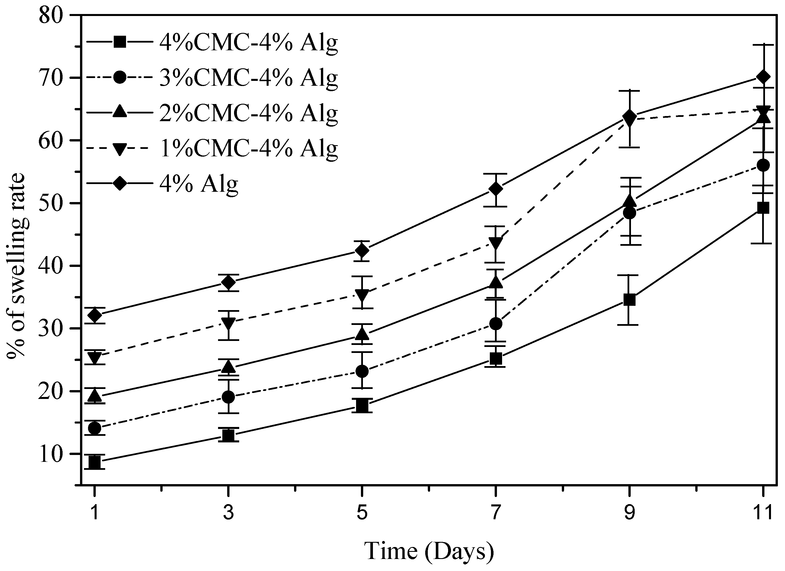
The swelling test is done following the protocol described in [76]. Briefly, sample filaments with various material compositions that is, 4% alginate, 4% alginate-1% CMC, 4% alginate-2% CMC, 4% alginate-3% CMC, 4% alginate-4% CMC has length of 1 cm are printed with a diameter of 250 μm dispensing nozzle. The sample number for each material combination is n = 3. Before storing them in liquid media, the weight of all the filaments is recorded and denoted as dry weight (Wd). All of the printed filaments are immersed in the culture media and incubator having ideal culture condition, that is, 37 °C and 5% CO2. The weights of the filaments are recorded every day up to 11 days and denoted this weight as wet weight (Ww). Using the following equation, % of swelling rate of these filaments is determined:
%   of   swelling   rate = W w W d W d × 100

2.8. Live/Dead Assay for Cell Viability

During deposition the cell-laden filament through dispensing nozzle, the cell experiences shear stress, which could be potentially harmful to the cell. Thereby, the cell viability and cytotoxicity is conducted using LIVE/DEAD assay after the printing and at the different time period. ReadyProbes™ Cell Viability Imaging Kit, Blue/Green (Thermofisher, Waltham, MA, USA) was used following the manufacturers protocol. The filament with the cells was imaged using Lionheart FX automated live cell imager (Biotek, Winooski, VT, USA). The z-stack images are captured using 50 μm layer thickness. The protocol is defined accordingly and beacon (n = 5) is selected randomly. Laser power and other detector parameters are kept constant throughout the imaging of the different beacons. The percentage of viability is determined using the following equation:
%   Viability = live   cell live + dead   cell × 100

2.9. Statistics

All the data are presented as a mean ± standard deviation. To evaluate the statistical significance of differences in viscosity, filament fusion, collapse tests, Young’s and reduced modulus, the distribution of values are considered to be normal. At a significance level of p = 0.05, a two-way ANOVA is performed to determine the statistically significant differences. Statistical software Minitab 18.0 and origin pro 5.0 are used to do the quantitative and graphical analysis.

3. Result and Discussion

3.1. Rheological Properties

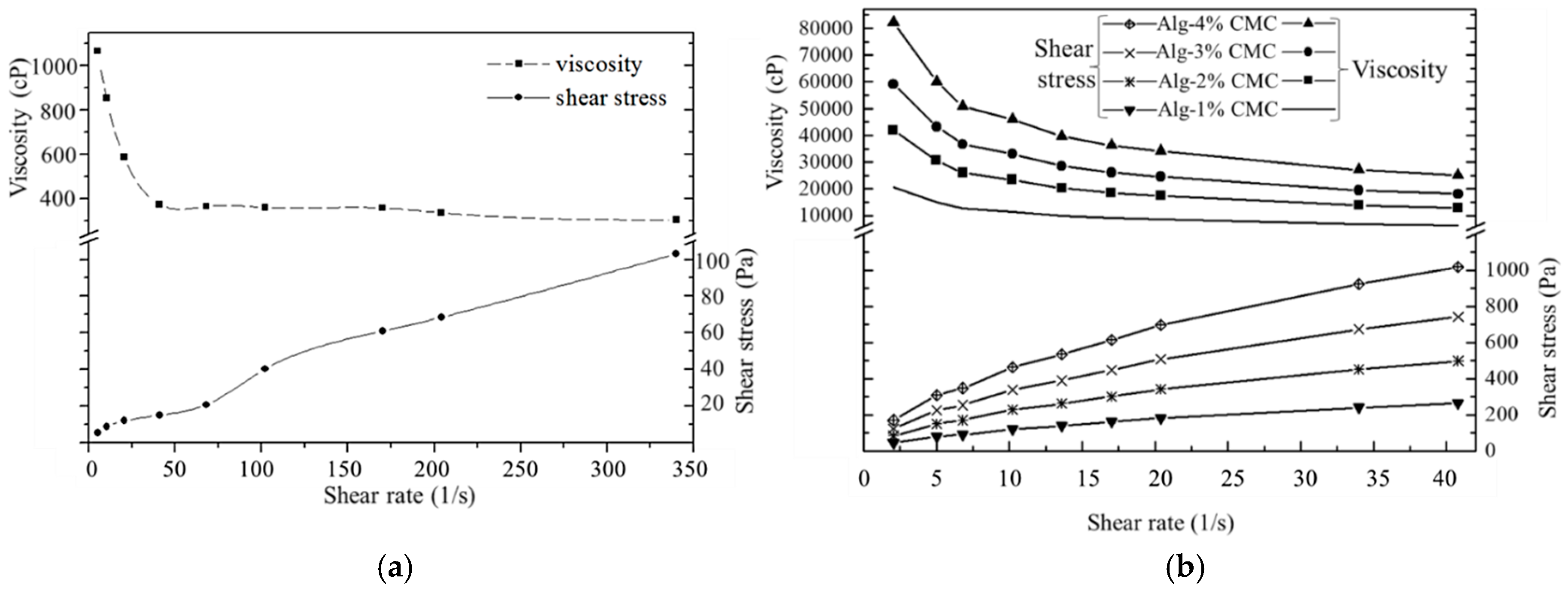
The shear thinning behavior, that is, decreasing the viscosity of the fluid with an increasing shear strain of pure alginate and Alg-CMC hydrogels is revealed from the stress curves as shown in Figure 9. In case of alginate/CMC, the shear thinning effect is pronounced more which reflects the greater possibility of this hybrid hydrogel to bio-print the clinically relevant scaffold.

3.2. Mechanical Test for Hydrogel

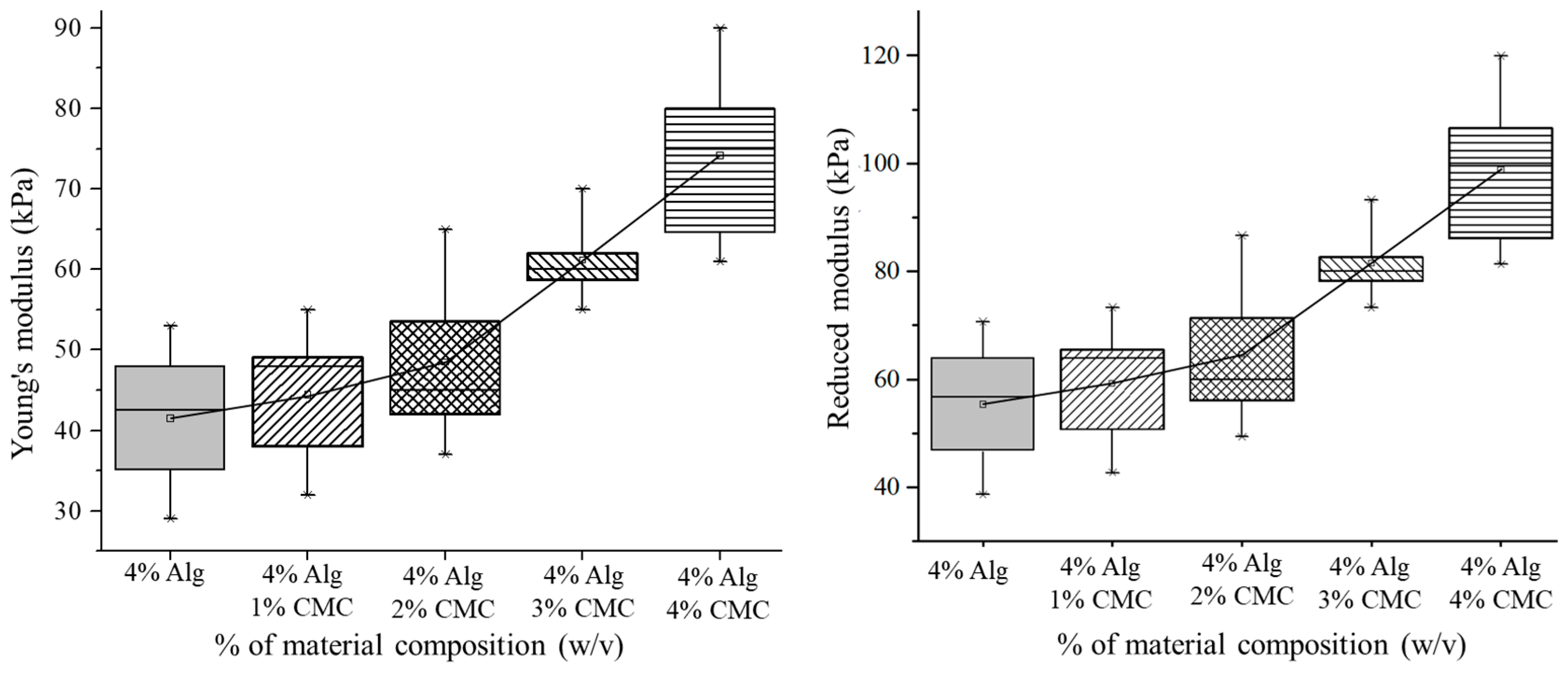
Mixing of CMC with alginate has increased the Young’s and Reduced Modulus of the blended hydrogel as shown in Figure 10. The mean value of the response, that is, Young’s modulus of various material concentrations is significantly different (p-value = 0 with 95% confidence interval). Incorporation of CMC into alginate increases the crosslinking density by increasing the Ca2+/–COO ionic interaction as shown in Figure 2. Moreover, the hydrogen bond between the same –COO ion of alginate and CMC makes the hybrid hydrogel stronger. Hence, with the increment of CMC percentage leads the upward trend of the Young’s and reduced modulus as shown in Figure 9.

3.3. Filament Fusion Test

To evaluate the effect of filament fusion and pore closure for each composition of the hydrogel, the area of the designed variational pore of the fabricated scaffold is measured as shown in Figure 10. The diffusion rate and printability of each pore are determined following the Equations (2) and (3) respectively. The diffusion rate shows decreasing trend where the printability shows an increasing trend with increasing the pore size for each composition of material as shown in Figure 11. Qualitatively, the 4% Alg-4%CMC shows good pore size and geometry than other material compositions. The quantitative analysis of diffusion rate validates that the composition of 4% Alg-4% CMC shows minimum material spreading, that is, minimum diffusion rate than other compositions. The range of printability of 4% Alg-4% CMC is 0.78 to 0.92 for the pore size 2–5 mm which demonstrates almost square geometry of the pore.

3.4. Filament Collapse Test

The qualitative observation of the collapse test for various compositions of material identifies that with increasing the percentage of CMC leads minimum deflection of the suspended filament as shown in Figure 12a. Composition with 4% Alg-4% CMC generates almost straight filament on the pillars situated at various distances. The collapse area factor for each distance value of each material composition is determined using the Equation (4). With increasing the pillar to pillar distance, the collapse area factor shows decreasing trend as shown in Figure 12b. The graph indicates the composition with 4% Alg-4% CMC has minimum collapse area factor even with increasing the distance value. Composition with 4% Alg-1% CMC is not able to hold the filament geometry and breaks away even at 4 mm distance value. The same scenario happens for 4% at 3 mm distance value. Hence, this event results in zero collapse area factors for these two compositions.

3.5. Effect of Nozzle Speed, Air Pressure and Print Distance on Filament Width

The nozzle speed directly influences the filament width for all types of material compositions as shown in Figure 13a. With increasing the nozzle speed, the filament width reduces for all material compositions as shown in Figure 13b.
With increasing the nozzle speed, the suspended filament experiences tension along deposition direction and become thinner. Higher nozzle speed may break down the filament results in a discontinuous material deposition. For each composition, the filament width is greater than the nozzle diameter because of material expansion after extrusion. The addition of CMC with alginate reduces the expansion of material after extrusion which results in less difference of the filament width with respect to original nozzle diameter at various nozzle speeds as shown in Figure 13b. Hence, composition with 4% Alg-4% CMC shows minimum filament width than other compositions.
The effect of print distance on filament width is shown in Figure 14a and Figure 15a. With increasing the print distance, the filament width is increasing. Apparently, the corner of the deposited filament changes from sharp to round with increasing print distance. Filament deposited from a higher distance get less contact with the build plane which leads the starting point of the deposition further away and results in accumulation of material. This event also creates curvy filament as shown in Figure 14a. With increasing the portion of CMC, the changes in filament width reduces with increasing print distance. Composition with 4% Alg-4% CMC shows a better corner and filament geometry and material deposition than a composition with 4% Alg-2% CMC.
With increasing the air pressure, the filament width of 4% Alg-2% CMC and 4% Alg-4% CMC composition increases as shown in Figure 14b and Figure 15b. However, the increased amount of CMC into alginate will reduce the changes of the filament width as shown in Figure 15b. Applying less air pressure may not exceed the surface tension of the material with the nozzle and eventually will not deposit continuous filament. Besides, over material deposition may happen due to high air pressure. Thereby, applying optimum air pressure for different material compositions will assure the continuous filament deposition as well as uniform filament width.

3.6. Qualitative and Quantitative Test of Lateral Pore

Scaffolds having a filament to filament distance of 3 mm are fabricated (10 layers) with compositions of 4% Alg-4% CMC and 4% Alg-2% CMC as shown in Figure 16a. Qualitatively, each pore of the scaffold fabricated by former composition is almost square. On the other hand, the pore geometry of scaffold fabricated by later composition is almost circular. To visualize the lateral pore in the scaffold structure clearly, the scaffold is cut laterally and observed the lateral pore macroscopically and microscopically. The presence of lateral pore in the scaffold fabricated by 4% Alg-4% CMC is quite clear. However, due to the higher collapse of the filament and comparatively less viscosity, lateral pore in the scaffold fabricated by 4% Alg-2% CMC was almost invisible. Therefore, it can be claimed that scaffold fabricated by 4% Alg-4% CMC maintains the lateral pore as well.
For given 3 mm filament to filament distance and 0.41 mm nozzle diameter, the theoretical lateral pore area is calculated as 1.1 mm2. The lateral pore area presented in the scaffold fabricated by 4% Alg-4% CMC is measured (n = 5) and compared with theoretical pore area. Using Equation (5), the lateral collapse area factor is determined as 37% for this specific filament to filament distance and nozzle diameter. Since, there was no lateral pore in the scaffold fabricated with 4% Alg-2% CMC, lateral collapse area factor for this composition is zero.

3.7. Scanning Electron Microscopy (SEM)

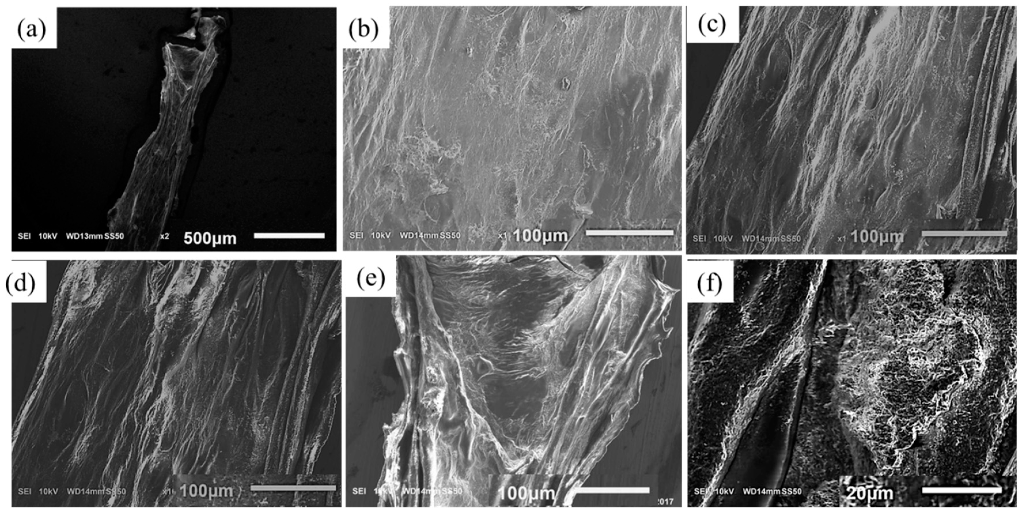
To study the influence of CMC on the filament microstructure, SEM imaging is performed with novel hybrid hydrogel 4% Alg-4% CMC in comparison to pure 4% alginate as shown in Figure 17. The cross-linked filament surface of pure alginate is smooth because of forming a primary membrane with Ca2+ as shown in Figure 17b. On the other hand, the filament surface fabricated with Alg-CMC hydrogel is highly porous as shown in Figure 17c assists potentially more to supply the nutrients and oxygen to the encapsulated cell. The filament incubated 3 days showing more pores as shown in Figure 17d–f indicating more release of CMC.

3.8. Swelling Test of Filament

All the compositions of material exhibit an upward trend of the swelling rate with the changes of time as shown in Figure 18. The mean swelling rate of each material combination at different time periods, that is, at day 1, 3, 5, 7, 9, 11 is significantly different (p-value = 0 with 95% confidence interval). Likewise, various material compositions show a significant difference in swelling rate among them as shown in Figure 18. Reducing the percentage of CMC increases the swelling rate and pure alginate shows maximum swelling. The reason behind this behavior is the addition of CMC increases the crosslinking density. Hence, the water absorption decreases and eventually the swelling rate.

3.9. Large-Scale Scaffold Fabrication

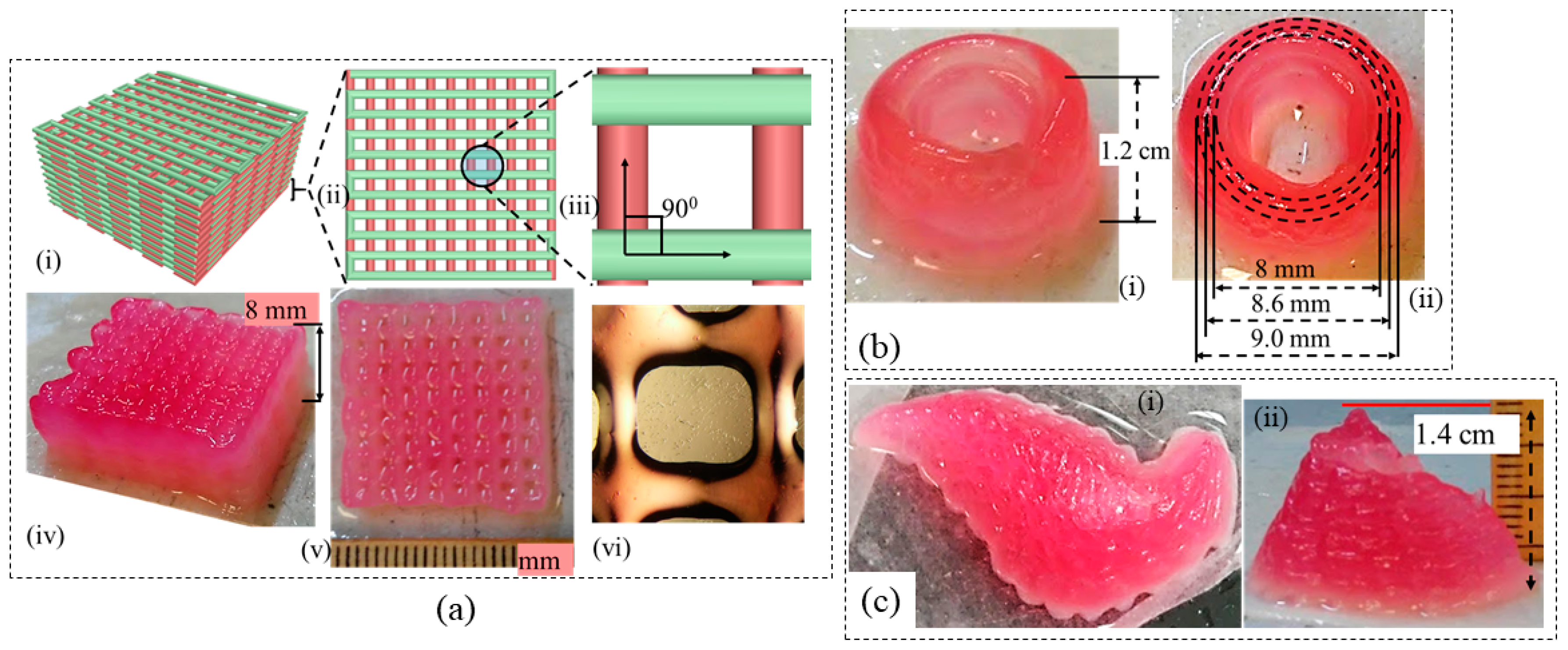
Once the aforementioned characterization tests are done, it is revealed, the composition of 4% Alg-4% CMC shows good printability and shape fidelity. Therefore, this composition is used to fabricate acellular large-scale scaffolds as shown in Figure 19. The represented scaffold figures demonstrate the capability of this composition to hold the shape fidelity of large-scale scaffold fabrication.

3.10. Analysis of Cell Viability

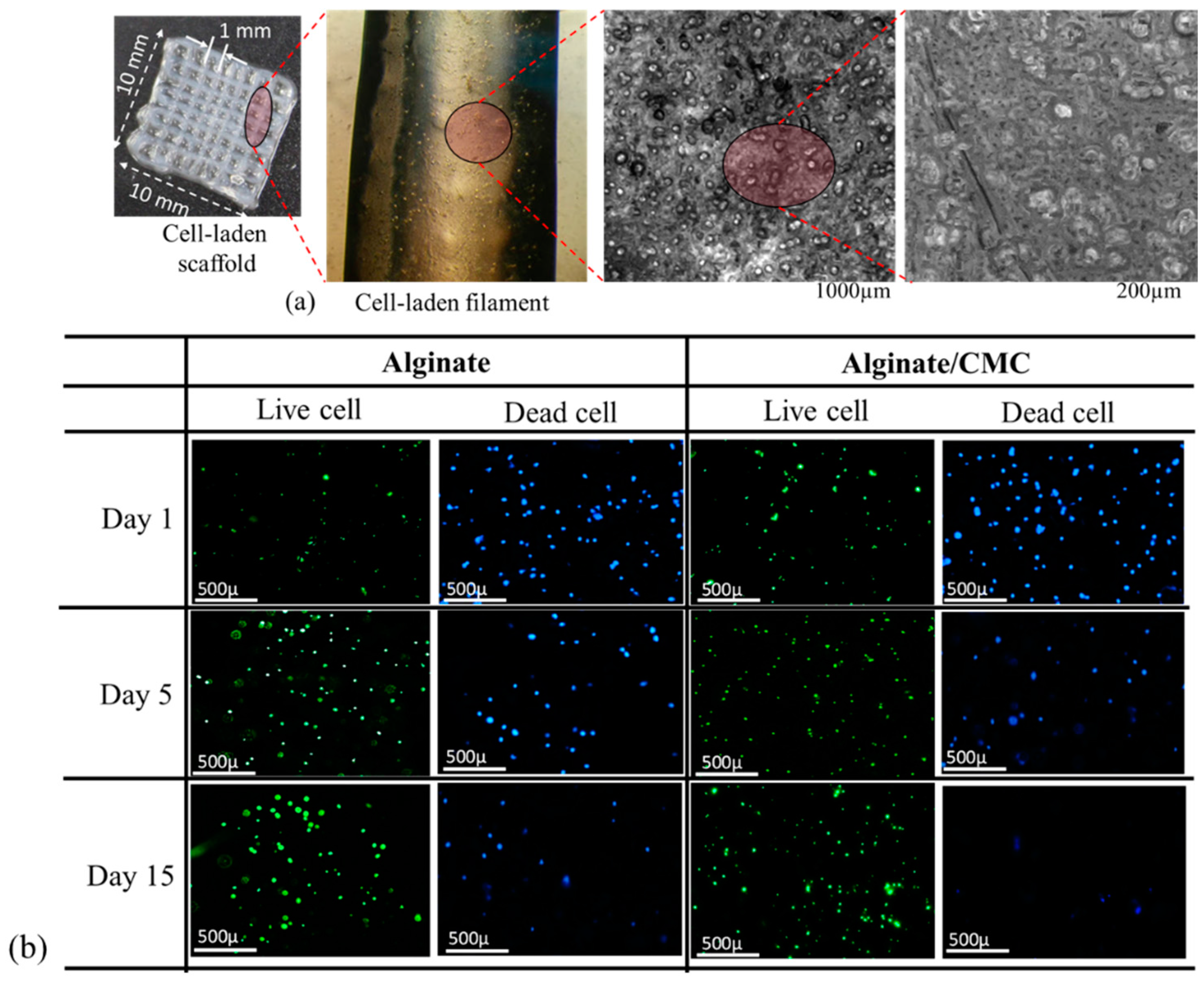
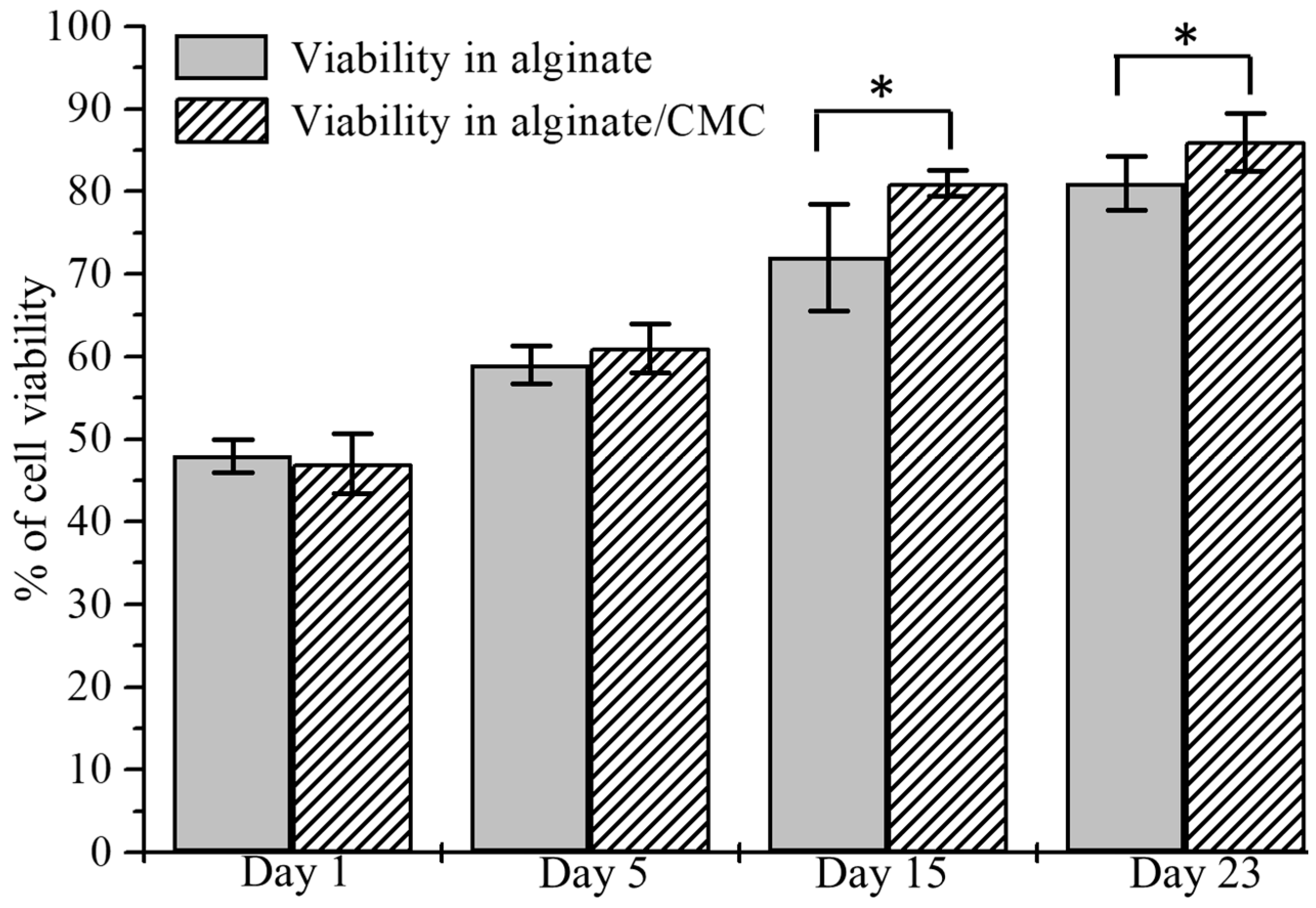
BxPC3 cells are mixed uniformly with pure alginate and 4% Alg-4% CMC using magnetic stirrer immediately prior to dispensing the hydrogel to fabricate the scaffold. Viability at different predefined time periods, that is, day 1, 5, 15, 23 using staining of the live/dead cell is determined. A significant amount of live and dead cell is observed after dispensing and cross-linking the hydrogels with CaCl2 as shown in Figure 20b. At the first day, the percentage of viability for alginate and alginate/CMC was almost similar and there was no significant difference. However, the cell viability into an alginate-CMC blend was higher and statistically different than into alginate at day 15 and 23 as shown in Figure 21. From the SEM image, it is quite clear that presence of CMC induces more porosity into the structure over time. Thereby, the cell-laden filament fabricated with 4% Alg-4% CMC allows more exchange of required growth factor and removal of waste material which drives towards higher cell viability.
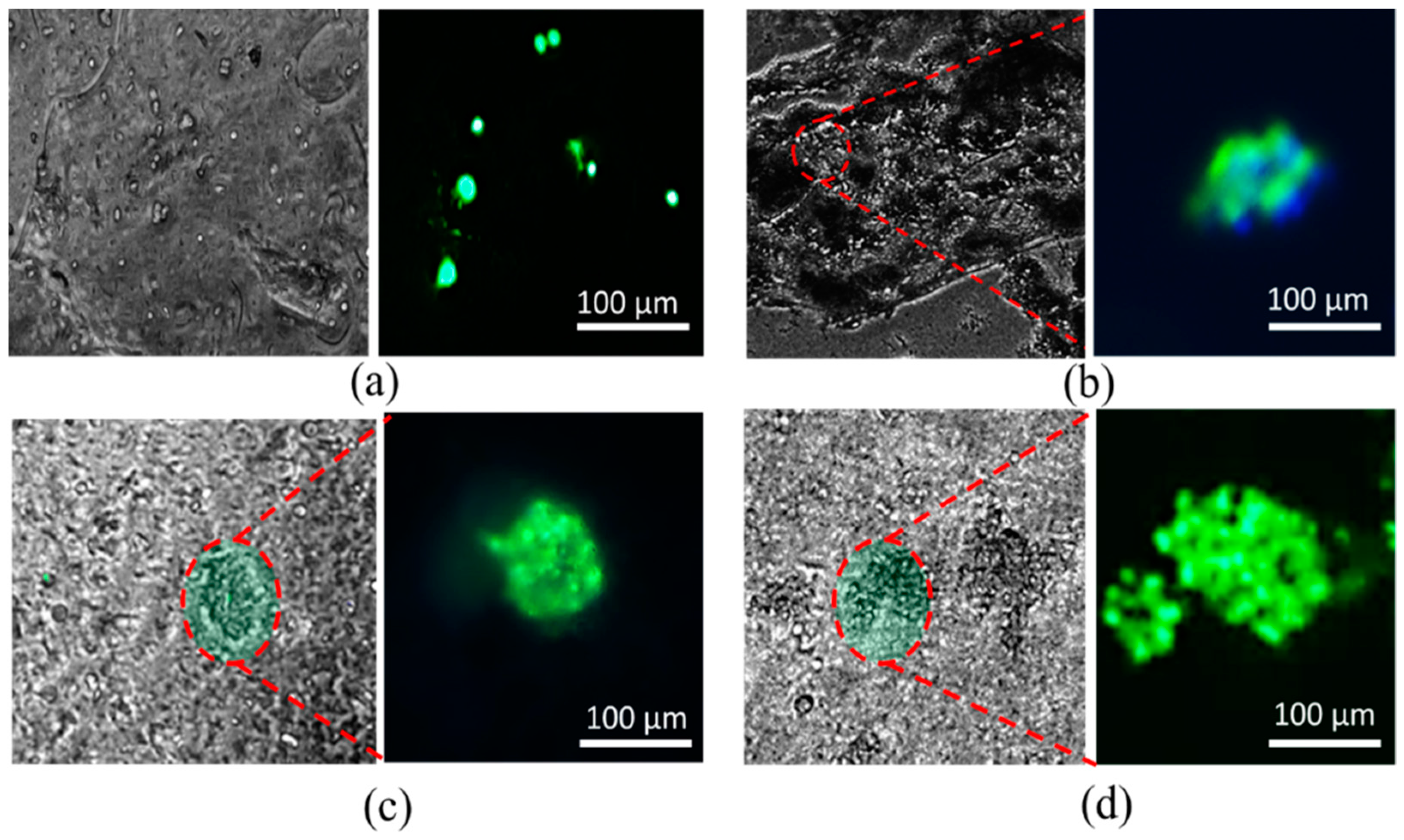
The morphology of BxPC3 cell is observed by phase contrast at different time periods into alginate and alginate/CMC. Minimum of five spots of spheroid morphology is visualized in each sample of alginate/CMC and the diameter of the spheroid is continued to increase as shown in Figure 22.

4. Conclusions

In this research, a novel hybrid hydrogel, that is, sodium alginate with carboxymethyl cellulose (CMC) is developed and optimized for 3D printing application. A set of systematic quantitative characterization tests are conducted to validate its printability, shape fidelity. The outcome of the rheological and mechanical test, filament collapse and fusion test demonstrate the favorable shape fidelity. Those characterization tests reveal that the composition of 4% Alg-4% CMC maintains good printability and shape fidelity for large-scale scaffold fabrication. Afterwards, 3D scaffold structures are fabricated with the pancreatic cancer cells, BxPC3 with these compositions and the cell viability is recorded 86% after 23 days which is comparable with pure alginate. To fabricate large-scale functional tissue scaffold, this hybrid hydrogel can be a potential biomaterial in 3D bioprinting process and the outlined characterization techniques open an avenue directing reproducible printability and shape fidelity. The future direction of this research is to fabricate large-scale cell-laden tissue scaffolds with different types of functional cell and determining the physiological behavior of co-culture into the microenvironment.

Acknowledgments

Financial support provided by National Science Foundation Grant # OIA-1355466 and by National Institute of Health under COBRE: CDTSPC Grant # P20GM109024 are acknowledged.

Author Contributions

Ahasan Habib and Bashir Khoda performed the experiments, analyze the results and prepare the manuscript; Sanku Mallik provided the BxPC3 cell and Venkatachalem Sathish performed the imaging and their analysis.

Conflicts of Interest

The authors declare no conflicts of interest.

References

  1. Murphy, S.V.; Atala, A. 3D bioprinting of tissues and organs. Nat. Biotechnol. 2014, 32, 773–785. [Google Scholar] [CrossRef] [PubMed]
  2. Jia, W.; Gungor-Ozkerim, P.S.; Zhang, Y.S.; Yue, K.; Zhu, K.; Liu, W.; Pi, Q.; Byambaa, B.; Dokmeci, M.R.; Shin, S.R.; et al. Direct 3D bioprinting of perfusable vascular constructs using a blend bioink. Biomaterials 2016, 106, 58–68. [Google Scholar] [CrossRef] [PubMed]
  3. Axpe, E.; Oyen, M.L. Applications of alginate-based bioinks in 3D bioprinting. Int. J. Mol. Sci. 2016, 17, 1976. [Google Scholar] [CrossRef] [PubMed]
  4. Skardal, A.; Atala, A. Biomaterials for integration with 3-D bioprinting. Ann. Biomed. Eng. 2015, 43, 730–746. [Google Scholar] [CrossRef] [PubMed]
  5. Khoda, A.; Ozbolat, I.T.; Koc, B. A functionally gradient variational porosity architecture for hollowed scaffolds fabrication. Biofabrication 2011, 3, 34106. [Google Scholar] [CrossRef] [PubMed]
  6. Zhu, W.; Qu, X.; Zhu, J.; Ma, X.; Patel, S.; Liu, J.; Wang, P.; Laia, C.S.E.; Gou, M.; Xu, Y. Direct 3D bioprinting of prevascularized tissue constructs with complex microarchitecture. Biomaterials 2017, 124, 106–115. [Google Scholar] [CrossRef] [PubMed]
  7. Skardal, A.; Zhang, J.; Prestwich, G.D. Bioprinting vessel-like constructs using hyaluronan hydrogels crosslinked with tetrahedral polyethylene glycol tetracrylates. Biomaterials 2010, 31, 6173–6181. [Google Scholar] [CrossRef] [PubMed]
  8. Paxton, N.C.; Smolan, W.; Böck, T.; Melchels, F.P.; Groll, J.; Juengst, T. Proposal to Assess. Printability of Bioinks for Extrusion-Based Bioprinting and Evaluation of Rheological Properties Governing Bioprintability. Biofabrication 2017, 9, 44107. [Google Scholar] [CrossRef] [PubMed]
  9. Ahn, G.; Min, K.-H.; Kim, C.; Lee, J.-S.; Kang, D.; Won, J.-Y.; Cho, D.-W.; Kim, J.-Y.; Jin, S.; Yun, W.-S.; et al. Precise stacking of decellularized extracellular matrix based 3D cell-laden constructs by a 3D cell printing system equipped with heating modules. Sci. Rep. 2017, 7, 8624. [Google Scholar] [CrossRef] [PubMed]
  10. Ribeiro, A.; Blokzijl, M.M.; Levato, R.; Visser, C.W.; Castilho, M.; Hennink, W.E. Assessing bioink shape fidelity to aid material development in 3D bioprinting. Biofabrication 2017, 10, 14102. [Google Scholar] [CrossRef] [PubMed]
  11. Yeong, W.-Y.; Chua, C.-K.; Leong, K.-F.; Chandrasekaran, M. Rapid prototyping in tissue engineering: Challenges and potential. Trends Biotechnol. 2004, 22, 643–652. [Google Scholar] [CrossRef] [PubMed]
  12. Leong, K.; Cheah, C.; Chua, C. Solid freeform fabrication of three-dimensional scaffolds for engineering replacement tissues and organs. Biomaterials 2003, 24, 2363–2378. [Google Scholar] [CrossRef]
  13. Pham, Q.P.; Sharma, U.; Mikos, A.G. Electrospinning of polymeric nanofibers for tissue engineering applications: A review. Tissue Eng. 2006, 12, 1197–1211. [Google Scholar] [CrossRef] [PubMed]
  14. Ferris, C.J.; Gilmore, K.G.; Wallace, G.G. Biofabrication: An overview of the approaches used for printing of living cells. Appl. Microbiol. Biotechnol. 2013, 97, 4243–4258. [Google Scholar] [CrossRef] [PubMed]
  15. Cipitria, A.; Lange, C.; Schell, H.; Wagermaier, W.; Reichert, J.C.; Hutmacher, D.W.; Duda, G.N. Porous scaffold architecture guides tissue formation. J. Bone Miner. Res. 2012, 27, 1275–1288. [Google Scholar] [CrossRef] [PubMed]
  16. Kang, H.-W.; Lee, S.J.; Ko, I.K.; Kengla, C.; Yoo, J.J.; Atala, A. A 3D bioprinting system to produce human-scale tissue constructs with structural integrity. Nat. Biotechnol. 2016, 34, 312–319. [Google Scholar] [CrossRef] [PubMed]
  17. Murphy, C.M.; Haugh, M.G.; O’Brien, F.J. The effect of mean pore size on cell attachment, proliferation and migration in collagen–glycosaminoglycan scaffolds for bone tissue engineering. Biomaterials 2010, 31, 461–466. [Google Scholar] [CrossRef] [PubMed]
  18. Perez, R.A.; Mestres, G. Role of pore size and morphology in musculo-skeletal tissue regeneration. Mater. Sci. Eng. C 2016, 61, 922–939. [Google Scholar] [CrossRef] [PubMed]
  19. Vijayavenkataraman, S.; Shuo, Z.; Fuh, J.Y.; Lu, W.F. Design of three-dimensional scaffolds with tunable matrix stiffness for directing stem cell lineage specification: An in silico study. Bioengineering 2017, 4, 66. [Google Scholar] [CrossRef] [PubMed]
  20. Li, H.; Tan, Y.J.; Leong, K.F.; Li, L. 3D bioprinting of highly thixotropic alginate/methylcellulose hydrogel with strong interface bonding. ACS Appl. Mater. Interfaces 2017, 9, 20086–20097. [Google Scholar] [CrossRef] [PubMed]
  21. Wang, L.; Xu, M.-E.; Luo, L.; Zhou, Y.; Si, P. Iterative feedback bio-printing-derived cell-laden hydrogel scaffolds with optimal geometrical fidelity and cellular controllability. Sci. Rep. 2018, 8, 2802. [Google Scholar] [CrossRef] [PubMed]
  22. Gaetani, R.; Doevendans, P.A.; Metz, C.H.; Alblas, J.; Messina, E.; Giacomello, A.; Sluijter, J.P. Cardiac tissue engineering using tissue printing technology and human cardiac progenitor cells. Biomaterials 2012, 33, 1782–1790. [Google Scholar] [CrossRef] [PubMed]
  23. Karande, T.S. Effect of Scaffold Architecture on Diffusion of Oxygen in Tissue Engineering Constructs; The University of Texas at Austin: Austin, TX, USA, 2007. [Google Scholar]
  24. Mandal, B.B.; Kundu, S.C. Cell proliferation and migration in silk fibroin 3D scaffolds. Biomaterials 2009, 30, 2956–2965. [Google Scholar] [CrossRef] [PubMed]
  25. Mygind, T.; Stiehler, M.; Baatrup, A.; Li, H.; Zou, X.; Flyvbjerg, A.; Bünger, C. Mesenchymal stem cell ingrowth and differentiation on coralline hydroxyapatite scaffolds. Biomaterials 2007, 28, 1036–1047. [Google Scholar] [CrossRef] [PubMed]
  26. Lien, S.-M.; Ko, L.-Y.; Huang, T.-J. Effect of pore size on ECM secretion and cell growth in gelatin scaffold for articular cartilage tissue engineering. Acta Biomater. 2009, 5, 670–679. [Google Scholar] [CrossRef] [PubMed]
  27. Loh, Q.L.; Choong, C. Three-dimensional scaffolds for tissue engineering applications: Role of porosity and pore size. Tissue Eng. Part B Rev. 2013, 19, 485–502. [Google Scholar] [CrossRef] [PubMed]
  28. Chen, S.; Zhang, Q.; Nakamoto, T.; Kawazoe, N.; Chen, G. Gelatin scaffolds with controlled pore structure and mechanical property for cartilage tissue engineering. Tissue Eng. Part C Methods 2016, 22, 189–198. [Google Scholar] [CrossRef] [PubMed]
  29. Neufurth, M.; Wang, X.; Schröder, H.C.; Feng, Q.; Diehl-Seifert, B.; Ziebart, T.; Müller, W.E. Engineering a morphogenetically active hydrogel for bioprinting of bioartificial tissue derived from human osteoblast-like SaOS-2 cells. Biomaterials 2014, 35, 8810–8819. [Google Scholar] [CrossRef] [PubMed]
  30. Xu, T.; Zhao, W.; Zhu, J.-M.; Albanna, M.Z.; Yoo, J.J.; Atala, A. Complex heterogeneous tissue constructs containing multiple cell types prepared by inkjet printing technology. Biomaterials 2013, 34, 130–139. [Google Scholar] [CrossRef] [PubMed]
  31. Xu, T.; Jin, J.; Gregory, C.; Hickman, J.J.; Boland, T. Inkjet printing of viable mammalian cells. Biomaterials 2005, 26, 93–99. [Google Scholar] [CrossRef] [PubMed]
  32. Wu, Y.; Wu, B.; Vijayavenkataraman, S.; San Wong, Y.; Fuh, J.Y.H. Crimped fiber with controllable patterns fabricated via electrohydrodynamic jet printing. Mater. Des. 2017, 131, 384–393. [Google Scholar] [CrossRef]
  33. Liu, H.; Vijayavenkataraman, S.; Wang, D.; Jing, L.; Sun, J.; He, K. Influence of electrohydrodynamic jetting parameters on the morphology of PCL scaffolds. Int. J. Bioprint. 2017, 3, 72–82. [Google Scholar] [CrossRef]
  34. Wang, H.; Vijayavenkataraman, S.; Wu, Y.; Shu, Z.; Sun, J.; Fuh, J.Y.H. Investigation of process parameters of electrohydro-dynamic jetting for 3D printed PCL fibrous scaffolds with complex geometries. Int. J. Bioprint. 2016, 2, 63–71. [Google Scholar] [CrossRef]
  35. Zhao, X.; He, J.; Xu, F.; Liu, Y.; Li, D. Electrohydrodynamic printing: A potential tool for high-resolution hydrogel/cell patterning. Virtual Phys. Prototyp. 2016, 11, 57–63. [Google Scholar] [CrossRef]
  36. Iwami, K.; Noda, T.; Ishida, K.; Morishima, K.; Nakamura, M.; Umeda, N. Bio rapid prototyping by extruding/aspirating/refilling thermoreversible hydrogel. Biofabrication 2010, 2, 14108. [Google Scholar] [CrossRef] [PubMed]
  37. Shor, L.; Güçeri, S.; Chang, R.; Gordon, J.; Kang, Q.; Hartsock, L.; Sun, W. Precision extruding deposition (PED) fabrication of polycaprolactone (PCL) scaffolds for bone tissue engineering. Biofabrication 2009, 1, 15003. [Google Scholar] [CrossRef] [PubMed]
  38. Barron, J.; Wu, P.; Ladouceur, H.; Ringeisen, B. Biological laser printing: A novel technique for creating heterogeneous 3-dimensional cell patterns. Biomed. Microdevices 2004, 6, 139–147. [Google Scholar] [CrossRef] [PubMed]
  39. Guillemot, F.; Souquet, A.; Catros, S.; Guillotin, B.; Lopez, J.; Faucon, M.S. Bellance High-throughput laser printing of cells and biomaterials for tissue engineering. Acta Biomater. 2010, 6, 2494–2500. [Google Scholar] [CrossRef] [PubMed]
  40. Guillotin, B.; Souquet, A.; Catros, S.; Duocastella, M.; Pippenger, B.; Bellance, S.; Amédée, J. Laser assisted bioprinting of engineered tissue with high cell density and microscale organization. Biomaterials 2010, 31, 7250–7256. [Google Scholar] [CrossRef] [PubMed]
  41. Peltola, S.M.; Melchels, F.P.; Grijpma, D.W.; Kellomäki, M. A review of rapid prototyping techniques for tissue engineering purposes. Ann. Med. 2008, 40, 268–280. [Google Scholar] [CrossRef] [PubMed] [Green Version]
  42. Wegrzyn, T.F.; Golding, M.; Archer, R.H. Food Layered Manufacture: A new process for constructing solid foods. Trends Food Sci. Technol. 2012, 27, 66–72. [Google Scholar] [CrossRef]
  43. Panesar, A.; Brackett, D.; Ashcroft, I.; Wildman, R.; Hague, R. Design Framework for Multifunctional Additive Manufacturing: Placement and Routing of Three-Dimensional Printed Circuit Volumes. J. Mech. Des. 2015, 137, 111414. [Google Scholar] [CrossRef]
  44. Krola, T.A.; Zaehb, M.F.; Seidela, C. Optimization of supports in metal-based additive manufacturing by means of finite element models. In Proceedings of the Solid Freeform Fabrication Symposium; SFF 23: Houston, TX, USA, 2012. [Google Scholar]
  45. Jones, N. Science in three dimensions: The print revolution. Nature 2012, 487, 22–23. [Google Scholar] [CrossRef] [PubMed]
  46. Moldovan, L.; Babbey, C.M.; Murphy, M.P.; Moldovan, N.I. Comparison of Biomaterial-Dependent and-Independent Bioprinting Methods for Cardiovascular Medicine. Curr. Opin. Biomed. Eng. 2017, 2, 124–131. [Google Scholar] [CrossRef]
  47. Chang, C.C.; Boland, E.D.; Williams, S.K.; Hoying, J.B. Direct-write bioprinting three-dimensional biohybrid systems for future regenerative therapies. J. Biomed. Mater. Res. Part B Appl. Biomater. 2011, 98, 160–170. [Google Scholar] [CrossRef] [PubMed]
  48. Fedorovich, N.E.; Alblas, J.; de Wijn, J.R.; Hennink, W.E.; Verbout, A.J.; Dhert, W.J. Hydrogels as extracellular matrices for skeletal tissue engineering: State-of-the-art and novel application in organ printing. Tissue Eng. 2007, 13, 1905–1925. [Google Scholar] [CrossRef] [PubMed]
  49. Murphy, S.V.; Skardal, A.; Atala, A. Evaluation of hydrogels for bio-printing applications. J. Biomed. Mater. Res. Part A 2013, 101, 272–284. [Google Scholar] [CrossRef] [PubMed]
  50. Benoit, D.S.; Schwartz, M.P.; Durney, A.R.; Anseth, K.S. Small functional groups for controlled differentiation of hydrogel-encapsulated human mesenchymal stem cells. Nat. Mater. 2008, 7, 816–823. [Google Scholar] [CrossRef] [PubMed]
  51. Gasperini, L.; Mano, J.F.; Reis, R.L. Natural polymers for the microencapsulation of cells. J. R. Soc. Interface 2014, 11, 20140817. [Google Scholar] [CrossRef] [PubMed]
  52. Hunt, N.C.; Shelton, R.M.; Henderson, D.J.; Grover, L.M. Calcium-alginate hydrogel-encapsulated fibroblasts provide sustained release of vascular endothelial growth factor. Tissue Eng. Part A 2012, 19, 905–914. [Google Scholar] [CrossRef] [PubMed]
  53. Sapir, Y.; Cohen, S.; Friedman, G.; Polyak, B. The promotion of in vitro vessel-like organization of endothelial cells in magnetically responsive alginate scaffolds. Biomaterials 2012, 33, 4100–4109. [Google Scholar] [CrossRef] [PubMed]
  54. Kundu, J.; Shim, J.H.; Jang, J.; Kim, S.W.; Cho, D.W. An additive manufacturing-based PCL-alginate-chondrocyte bioprinted scaffold for cartilage tissue engineering. J. Tissue Eng. Regen. Med. 2015, 9, 1286–1297. [Google Scholar] [CrossRef] [PubMed]
  55. Mosahebi, A.; Simon, M.; Wiberg, M.; Terenghi, G. A novel use of alginate hydrogel as Schwann cell matrix. Tissue Eng. 2001, 7, 525–534. [Google Scholar] [CrossRef] [PubMed]
  56. Hunt, N.; Smith, A.M.; Gbureck, U.; Shelton, R.; Grover, L. Encapsulation of fibroblasts causes accelerated alginate hydrogel degradation. Acta Biomater. 2010, 6, 3649–3656. [Google Scholar] [CrossRef] [PubMed]
  57. He, Y.; Yang, F.; Zhao, H.; Gao, Q.; Xia, B.; Fu, J. Research on the printability of hydrogels in 3D bioprinting. Sci. Rep. 2016, 6, 29977. [Google Scholar] [CrossRef] [PubMed]
  58. Khalil, S.; Sun, W. Bioprinting endothelial cells with alginate for 3D tissue constructs. J. Biomech. Eng. 2009, 131, 111002. [Google Scholar] [CrossRef] [PubMed]
  59. Ouyang, L.; Yao, R.; Zhao, Y.; Sun, W. Effect of bioink properties on printability and cell viability for 3D bioplotting of embryonic stem cells. Biofabrication 2016, 8, 35020. [Google Scholar] [CrossRef] [PubMed]
  60. Ahlfeld, T.; Cidonio, G.; Kilian, D.; Duin, S.; Akkineni, A.; Dawson, J.; Gelinsky, M. Development of a clay based bioink for 3D cell printing for skeletal application. Biofabrication 2017, 9, 34103. [Google Scholar] [CrossRef] [PubMed]
  61. Narayanan, L.K.; Huebner, P.; Fisher, M.B.; Spang, J.T.; Starly, B.; Shirwaiker, R.A. 3D-bioprinting of polylactic acid (PLA) nanofiber–alginate hydrogel bioink containing human adipose-derived stem cells. ACS Biomater. Sci. Eng. 2016, 2, 1732–1742. [Google Scholar] [CrossRef]
  62. Schütz, K.; Placht, A.M.; Paul, B.; Brüggemeier, S.; Gelinsky, M.; Lode, A. Three-dimensional plotting of a cell-laden alginate/methylcellulose blend: Towards biofabrication of tissue engineering constructs with clinically relevant dimensions. J. Tissue Eng. Regen. Med. 2017, 11, 1574–1587. [Google Scholar] [CrossRef] [PubMed]
  63. Ivanovska, J.; Zehnder, T.; Lennert, P.; Sarker, B.; Boccaccini, A.R.; Hartmann, A.; Detsch, R. Biofabrication of 3D alginate-based hydrogel for cancer research: Comparison of cell spreading, viability, and adhesion characteristics of colorectal HCT116 tumor cells. Tissue Eng. Part C Methods 2016, 22, 708–715. [Google Scholar] [CrossRef] [PubMed]
  64. Hölzl, K.; Lin, S.; Tytgat, L.; van Vlierberghe, S.; Gu, L.; Ovsianikov, A. Bioink properties before, during and after 3D bioprinting. Biofabrication 2016, 8, 32002. [Google Scholar] [CrossRef] [PubMed]
  65. Li, H.; Liu, S.; Lin, L. Rheological study on 3D printability of alginate hydrogel and effect of graphene oxide. Int. J. Bioprint. 2016, 2, 163–175. [Google Scholar] [CrossRef]
  66. Wüst, S.; Godla, M.E.; Müller, R.; Hofmann, S. Tunable hydrogel composite with two-step processing in combination with innovative hardware upgrade for cell-based three-dimensional bioprinting. Acta Biomater. 2014, 10, 630–640. [Google Scholar] [CrossRef] [PubMed]
  67. Shim, J.-H.; Lee, J.-S.; Kim, J.Y.; Cho, D.-W. Bioprinting of a mechanically enhanced three-dimensional dual cell-laden construct for osteochondral tissue engineering using a multi-head tissue/organ building system. J. Micromech. Microeng. 2012, 22, 85014. [Google Scholar] [CrossRef]
  68. Garrett, Q.; Simmons, P.A.; Xu, S.; Vehige, J.; Zhao, Z.; Ehrmann, K.; Willcox, M. Carboxymethylcellulose binds to human corneal epithelial cells and is a modulator of corneal epithelial wound healing. Investig. Ophthalmol. Vis. Sci. 2007, 48, 1559–1567. [Google Scholar] [CrossRef] [PubMed]
  69. Kim, M.S.; Park, S.J.; Gu, B.K.; Kim, C.-H. Ionically crosslinked alginate–carboxymethyl cellulose beads for the delivery of protein therapeutics. Appl. Surf. Sci. 2012, 262, 28–33. [Google Scholar] [CrossRef]
  70. Agarwal, T.; Narayana, S.G.H.; Pal, K.; Pramanik, K.; Giri, S.; Banerjee, I. Calcium alginate-carboxymethyl cellulose beads for colon-targeted drug delivery. Int. J. Biol. Macromol. 2015, 75, 409–417. [Google Scholar] [CrossRef] [PubMed]
  71. Blaeser, A.; Duarte Campos, D.F.; Weber, M.; Neuss, S.; Theek, B.; Fischer, H.; Jahnen-Dechent, W. Biofabrication under fluorocarbon: A novel freeform fabrication technique to generate high aspect ratio tissue-engineered constructs. BioRes. Open Access 2013, 2, 374–384. [Google Scholar] [CrossRef] [PubMed]
  72. Han, Y.; Wang, L. Sodium alginate/carboxymethyl cellulose films containing pyrogallic acid: Physical and antibacterial properties. J. Sci. Food Agric. 2017, 97, 1295–1301. [Google Scholar] [CrossRef] [PubMed]
  73. Tongdeesoontorn, W.; Mauer, L.J.; Wongruong, S.; Sriburi, P.; Rachtanapun, P. Effect of carboxymethyl cellulose concentration on physical properties of biodegradable cassava starch-based films. Chem. Cent. J. 2011, 5, 6. [Google Scholar] [CrossRef] [PubMed]
  74. Habib, M.A.; Khoda, B. Support grain architecture design for additive manufacturing. J. Manuf. Process. 2017, 29, 332–342. [Google Scholar] [CrossRef]
  75. Therriault, D.; White, S.R.; Lewis, J.A. Rheological behavior of fugitive organic inks for direct-write assembly. Appl. Rheol. 2007, 17, 10112–11411. [Google Scholar]
  76. You, F.; Wu, X.; Zhu, N.; Lei, M.; Eames, B.F.; Chen, X. 3D printing of porous cell-laden hydrogel constructs for potential applications in cartilage tissue engineering. ACS Biomater. Sci. Eng. 2016, 2, 1200–1210. [Google Scholar] [CrossRef]
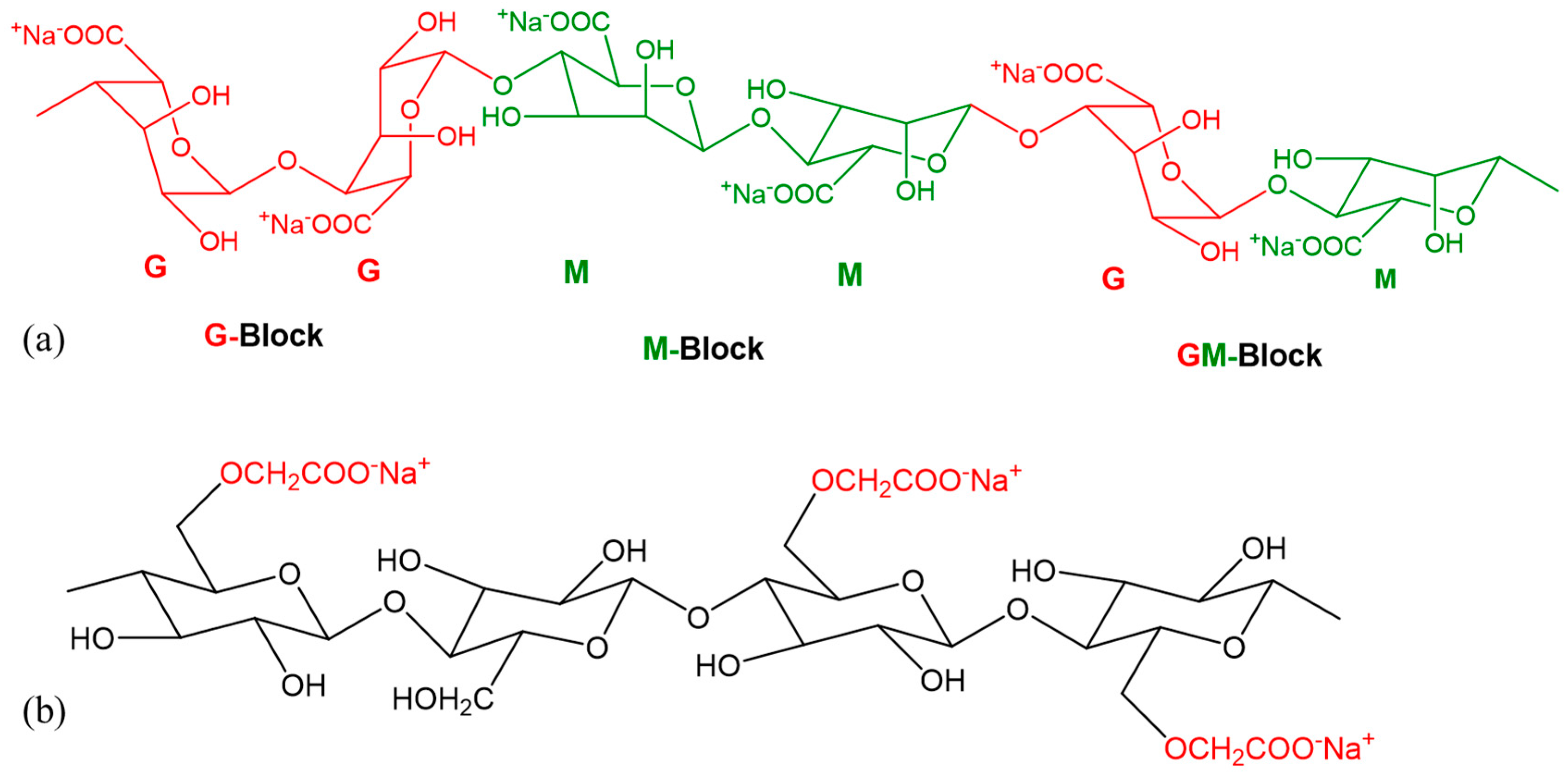
Figure 1. Chemical formula of (a) Alginate; (b) Carboxymethyl Cellulose (CMC).
Materials 11 00454 g001
Figure 2. Preparation of (a) Alginate and (b) Alginate-CMC.
Materials 11 00454 g002
Figure 3. The schematic diagram of in-house built 3D bio-printer.
Materials 11 00454 g003
Figure 4. Filament deposited along (a) 0°; (b) 90° and (c) 0°–90°.
Materials 11 00454 g004
Figure 5. (a) Model and fabricated part of the platform; (b) Determination of collapse area factor.
Materials 11 00454 g005
Figure 6. (a) Qualitative; and (b) Quantitative test of lateral pore.
Materials 11 00454 g006
Figure 7. (a) Preparation of cell-laden hydrogel; (b) bio-printing of the cell-laden hydrogel; and (c) incubation of fabricated scaffold. Rheology.
Materials 11 00454 g007
Figure 8. Rheological properties of (a) Alginate and (b) Alginate-CMC.
Materials 11 00454 g008
Figure 9. Young’s and Reduced Modulus.
Materials 11 00454 g009
Figure 10. Filament fusion test.
Materials 11 00454 g010
Figure 11. Diffusion rate and printability in filament fusion test.
Materials 11 00454 g011
Figure 12. (a) Filament collapse test and (b) Collapse area factor.
Materials 11 00454 g012
Figure 13. (a) Printed filaments at different nozzle speed; (b) the effect of nozzle speed on filament width.
Materials 11 00454 g013
Figure 14. Qualitative effect of (a) print distance; (b) air pressure.
Materials 11 00454 g014
Figure 15. Effect of (a) Print distance; (b) Air pressure.
Materials 11 00454 g015
Figure 16. (a) Qualitative and (b) Quantitative test for lateral pore.
Materials 11 00454 g016
Figure 17. Scanning electron microscopy of filament with (a,b) 4% Alg and (c) 4% Alg-4% CMC before incubation; (df) 4% Alg-4% CMC after 3 days of incubation.
Materials 11 00454 g017
Figure 18. Swelling rate of different compositions of material.
Materials 11 00454 g018
Figure 19. Large-scale scaffold fabricated by 4% Alg-4% CMC (a) CAD design (i–iii) with 0–90 deg pattern and corresponding fabrication (iv–vi); (b) a thin wall cylinder; (c) Pancreas structure from anatomical model.
Materials 11 00454 g019
Figure 20. (a) Cell-laden scaffold and filament and (b) Live/dead staining of BxPC3 cell encapsulated in alginate and Alg-CMC hydrogel at different time periods.
Materials 11 00454 g020
Figure 21. Comparison of cell viability into alginate and Alg-CMC at the different time.
Materials 11 00454 g021
Figure 22. Generation of cell spheroid at day (a) 1; (b) 5; (c) 15 and (d) 23.
Materials 11 00454 g022