Recent Developments in the Optimization of the Bulk Heterojunction Morphology of Polymer: Fullerene Solar Cells

 ,
,  , ,
, ,  ,
, 
Abstract
:1. Introduction
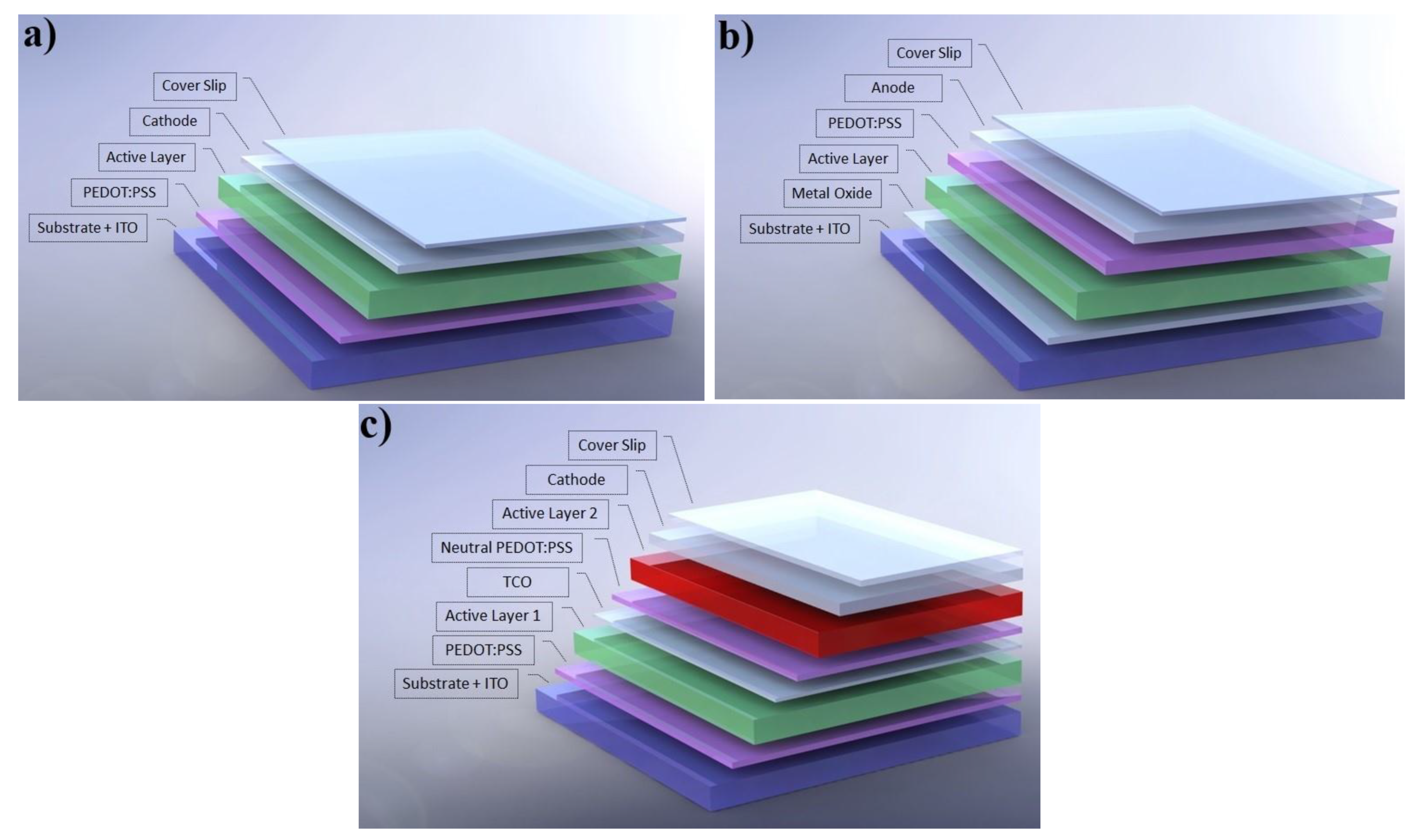
1.1. Device Architectures
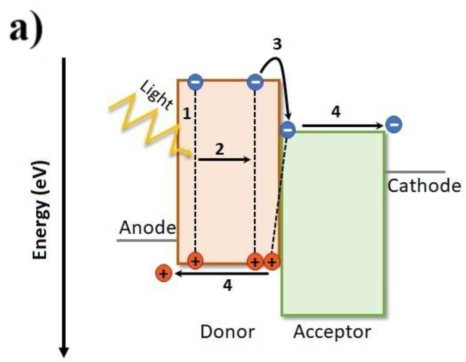
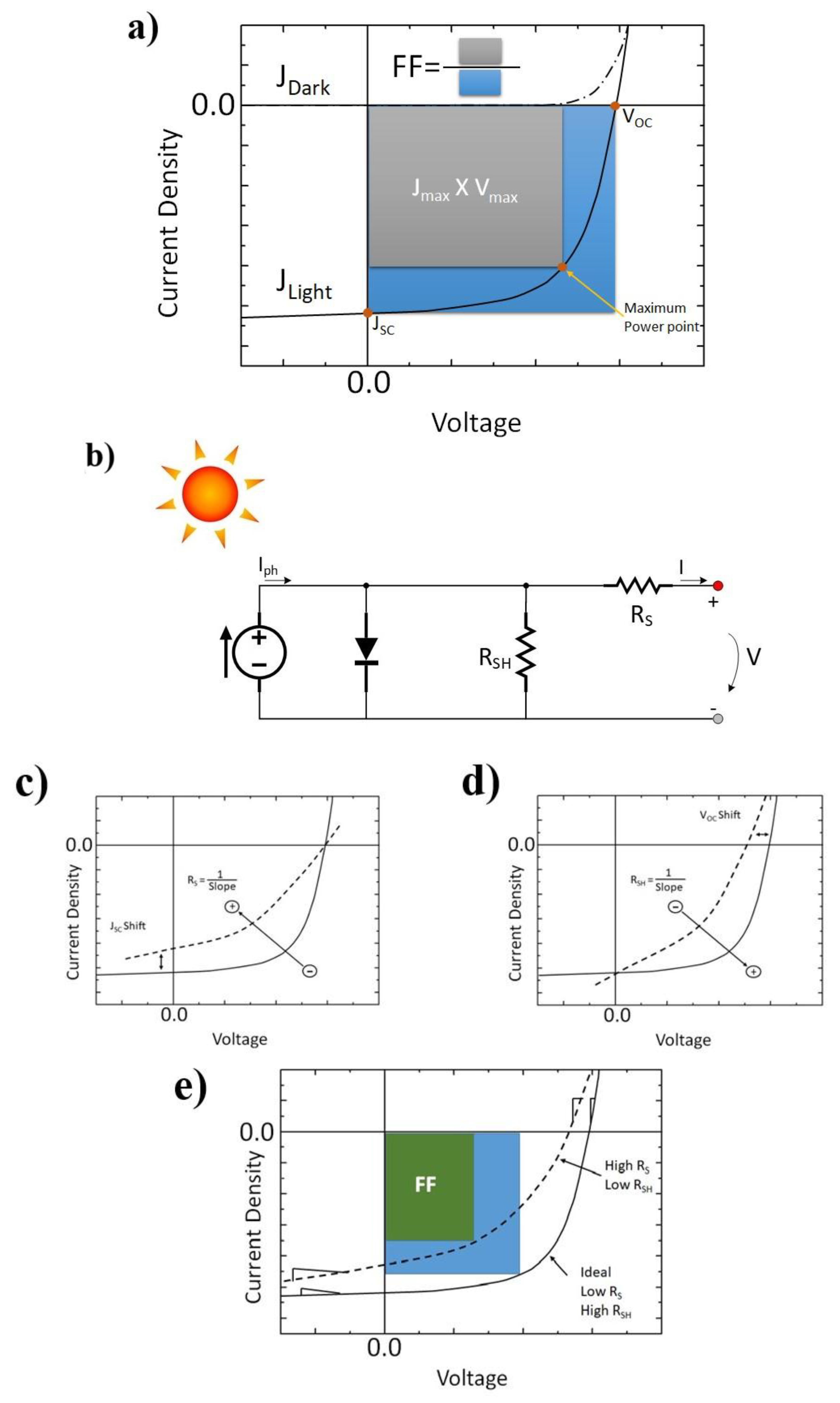
1.2. Macroscopic Device Physics
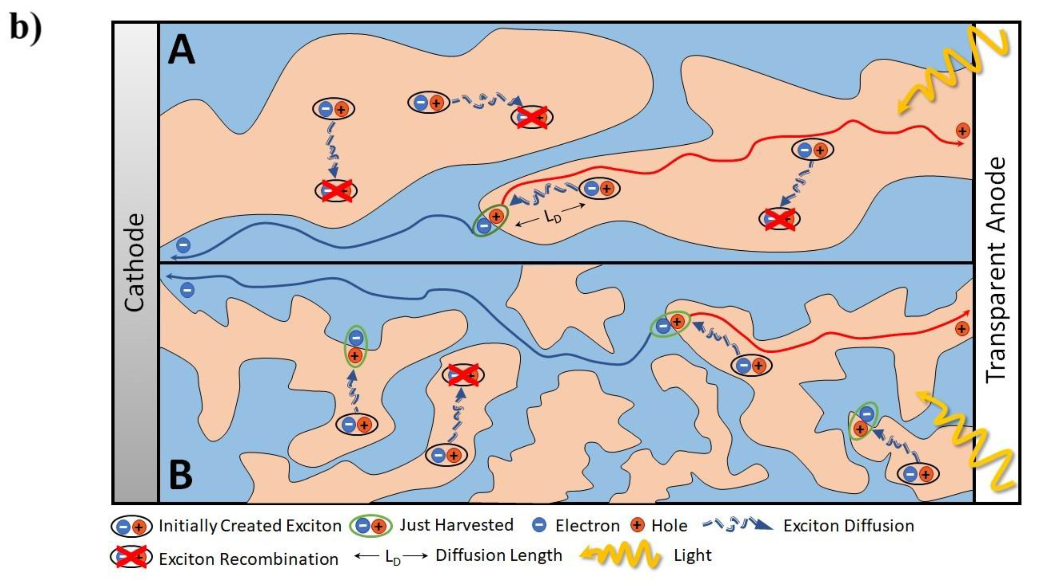
1.3. Relationship between Nanoscopic and Macroscopic Device Physics
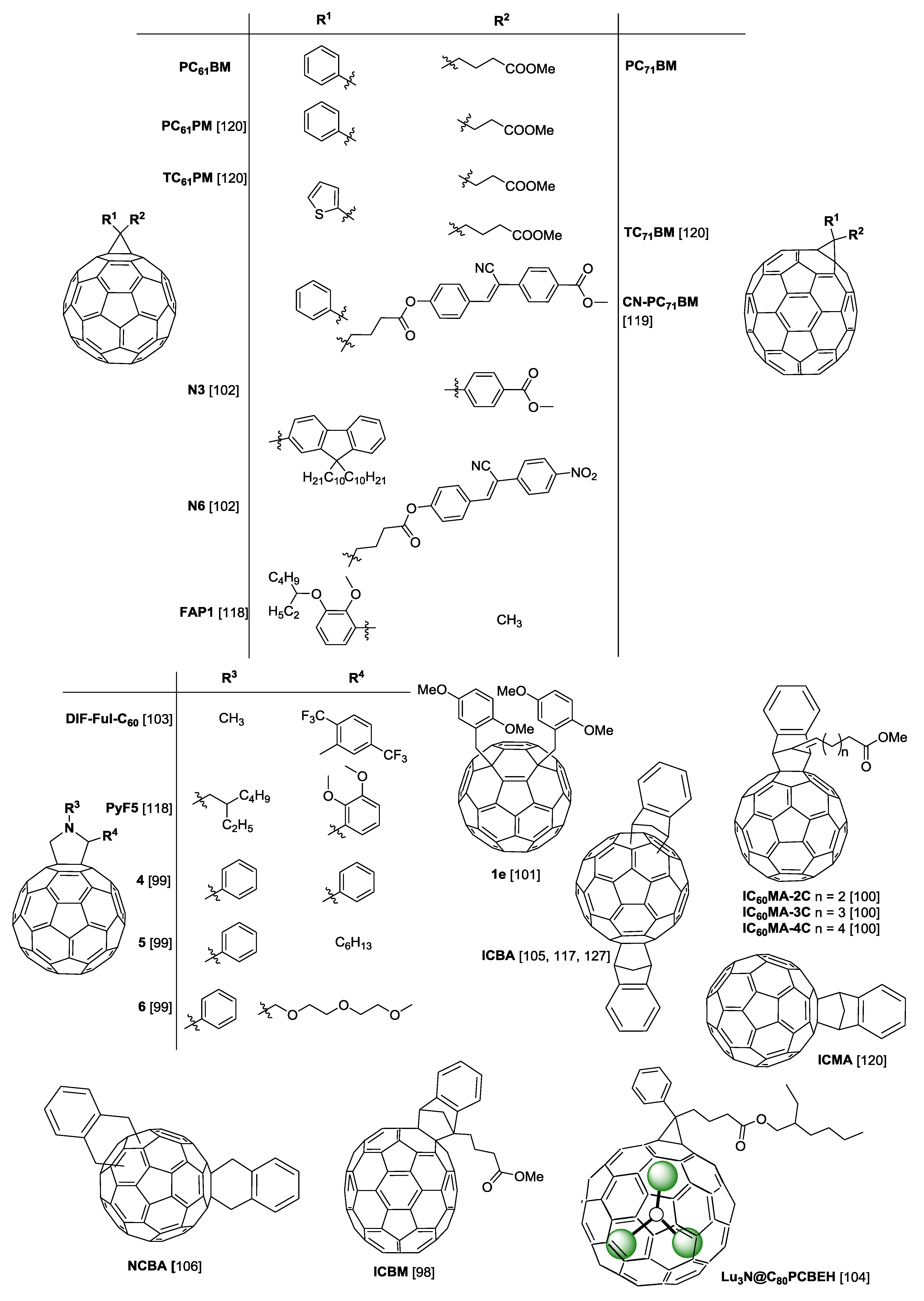
2. Polymers and Fullerenes
3. Additives
4. Devices Based on PTB7
4.1. PTB7 Devices with PC61BM and PC71BM
4.2. PTB7 Devices with Other Fullerenes
5. Devices Based on PTB7-Th
5.1. PTB7-Th Devices with PC61BM and PC71BM
5.2. PTB7-Th Devices with Other Fullerenes
6. Devices Based on PffBT4T-2OD
6.1. PffBT4T-2OD Devices with PC61BM and PC71BM
6.2. PffBT4T-2OD Devices with Other Fullerenes
7. Conclusions and Perspectives
Author Contributions
Funding
Conflicts of Interest
References
- Søndergaard, R.; Hösel, M.; Angmo, D.; Larsen-Olsen, T.T.; Krebs, F.C. Roll-to-roll fabrication of polymer solar cells. Mater. Today 2012, 15, 36–49. [Google Scholar] [CrossRef] [Green Version]
- Andersen, T.R.; Cooling, N.A.; Almyahi, F.; Hart, A.S.; Nicolaidis, N.C.; Feron, K.; Noori, M.; Vaughan, B.; Griffith, M.J.; Belcher, W.J.; et al. Fully roll-to-roll prepared organic solar cells in normal geometry with a sputter-coated aluminium top-electrode. Sol. Energy Mater. Sol. Cells 2016, 149, 103–109. [Google Scholar] [CrossRef]
- Huang, Y.-C.; Cha, H.-C.; Chen, C.-Y.; Tsao, C.-S. A universal roll-to-roll slot-die coating approach towards high-efficiency organic photovoltaics. Prog. Photovolt. Res. Appl. 2017, 25, 928–935. [Google Scholar] [CrossRef]
- Galagan, Y.; Fledderus, H.; Gorter, H.; ’t Mannetje, H.H.; Shanmugam, S.; Mandamparambil, R.; Bosman, J.; Rubingh, J.-E.J.M.; Teunissen, J.-P.; Salem, A.; et al. Roll-to-Roll Slot–Die Coated Organic Photovoltaic (OPV) Modules with High Geometrical Fill Factors. Energy Technol. 2015, 3, 834–842. [Google Scholar] [CrossRef]
- Kapnopoulos, C.; Mekeridis, E.D.; Tzounis, L.; Polyzoidis, C.; Zachariadis, A.; Tsimikli, S.; Gravalidis, C.; Laskarakis, A.; Vouroutzis, N.; Logothetidis, S. Fully gravure printed organic photovoltaic modules: A straightforward process with a high potential for large scale production. Sol. Energy Mater. Sol. Cells 2016, 144, 724–731. [Google Scholar] [CrossRef]
- Vak, D.; Weerasinghe, H.; Ramamurthy, J.; Subbiah, J.; Brown, M.; Jones, D.J. Reverse gravure coating for roll-to-roll production of organic photovoltaics. Sol. Energy Mater. Sol. Cells 2016, 149, 154–161. [Google Scholar] [CrossRef]
- Xiao, Z.; Jia, X.; Ding, L.M. Ternary organic solar cells offer 14% power conversion efficiency. Sci. Bull. 2017, 62, 1562–1564. [Google Scholar] [CrossRef]
- Li, S.; Ye, L.; Zhao, W.; Yan, H.; Yang, B.; Liu, D.; Li, W.; Ade, H.; Hou, J. A Wide Band Gap Polymer with a Deep Highest Occupied Molecular Orbital Level Enables 14.2% Efficiency in Polymer Solar Cells. J. Am. Chem. Soc. 2018, 140, 7159–7167. [Google Scholar] [CrossRef]
- Meng, L.; Zhang, Y.; Wan, X.; Li, C.; Zhang, X.; Wang, Y.; Ke, X.; Xiao, Z.; Ding, L.; Xia, R.; et al. Organic and solution-processed tandem solar cells with 17.3% efficiency. Science 2018. [Google Scholar] [CrossRef]
- Cheng, P.; Li, G.; Zhan, X.W.; Yang, Y. Next-generation organic photovoltaics based on non-fullerene acceptors. Nat. Photonics 2018, 12, 131–142. [Google Scholar] [CrossRef]
- Zhang, J.Q.; Tan, H.S.; Guo, X.G.; Facchetti, A.; Yan, H. Material insights and challenges for non-fullerene organic solar cells based on small molecular acceptors. Nat. Energy 2018, 3, 720–731. [Google Scholar] [CrossRef]
- Yan, C.Q.; Barlow, S.; Wang, Z.H.; Yan, H.; Jen, A.K.Y.; Marder, S.R.; Zhan, X.W. Non-fullerene acceptors for organic solar cells. Nat. Rev. Mater. 2018, 3, 18003. [Google Scholar] [CrossRef]
- Hou, J.; Inganäs, O.; Friend, R.H.; Gao, F. Organic solar cells based on non-fullerene acceptors. Nat. Mater. 2018, 17, 119. [Google Scholar] [CrossRef] [PubMed]
- Chen, W.Q.; Zhang, Q.C. Recent progress in non-fullerene small molecule acceptors in organic solar cells (OSCs). J. Mater. Chem. C 2017, 5, 1275–1302. [Google Scholar] [CrossRef]
- Lin, Y.Z.; Zhan, X.W. Non-fullerene acceptors for organic photovoltaics: An emerging horizon. Mater. Horiz. 2014, 1, 470–488. [Google Scholar] [CrossRef]
- Määttänen, A.; Ihalainen, P.; Pulkkinen, P.; Wang, S.; Tenhu, H.; Peltonen, J. Inkjet-Printed Gold Electrodes on Paper: Characterization and Functionalization. ACS Appl. Mater. Interfaces 2012, 4, 955–964. [Google Scholar] [CrossRef]
- Noguchi, Y.; Sekitani, T.; Yokota, T.; Someya, T. Direct inkjet printing of silver electrodes on organic semiconductors for thin-film transistors with top contact geometry. Appl. Phys. Lett. 2008, 93, 273. [Google Scholar] [CrossRef]
- Norita, S.; Kumaki, D.; Kobayashi, Y.; Sato, T.; Fukuda, K.; Tokito, S. Inkjet-printed copper electrodes using photonic sintering and their application to organic thin-film transistors. Org. Electron. 2015, 25, 131–134. [Google Scholar] [CrossRef] [Green Version]
- Wang, K.; Liu, C.; Meng, T.; Yi, C.; Gong, X. Inverted organic photovoltaic cells. Chem. Soc. Rev. 2016, 45, 2937–2975. [Google Scholar] [CrossRef]
- Seo, J.H.; Jin, Y.; Brzezinski, J.Z.; Walker, B.; Nguyen, T.Q. Exciton Binding Energies in Conjugated Polyelectrolyte Films. Chemphyschem 2009, 10, 1023–1027. [Google Scholar] [CrossRef]
- Menke, S.M.; Ran, N.A.; Bazan, G.C.; Friend, R.H. Understanding Energy Loss in Organic Solar Cells: Toward a New Efficiency Regime. Joule 2018, 2, 25–35. [Google Scholar] [CrossRef]
- Scharber, M.C.; Sariciftci, N.S. Efficiency of bulk-heterojunction organic solar cells. Prog. Polym. Sci. 2013, 38, 1929–1940. [Google Scholar] [CrossRef] [PubMed]
- Baran, D.; Kirchartz, T.; Wheeler, S.; Dimitrov, S.; Abdelsamie, M.; Gorman, J.; Ashraf, R.S.; Holliday, S.; Wadsworth, A.; Gasparini, N.; et al. Reduced voltage losses yield 10% efficient fullerene free organic solar cells with >1 V open circuit voltages. Energy Environ. Sci. 2016, 9, 3783–3793. [Google Scholar] [CrossRef] [PubMed] [Green Version]
- Luhman, W.A.; Holmes, R.J. Investigation of Energy Transfer in Organic Photovoltaic Cells and Impact on Exciton Diffusion Length Measurements. Adv. Funct. Mater. 2011, 21, 764–771. [Google Scholar] [CrossRef]
- Mikhnenko, O.V.; Azimi, H.; Scharber, M.; Morana, M.; Blom, P.W.M.; Loi, M.A. Exciton diffusion length in narrow bandgap polymers. Energy Environ. Sci. 2012, 5, 6960–6965. [Google Scholar] [CrossRef]
- Menke, S.M.; Holmes, R.J. Exciton diffusion in organic photovoltaic cells. Energy Environ. Sci. 2014, 7, 499–512. [Google Scholar] [CrossRef]
- Tamai, Y.; Ohkita, H.; Benten, H.; Ito, S. Exciton Diffusion in Conjugated Polymers: From Fundamental Understanding to Improvement in Photovoltaic Conversion Efficiency. J. Phys. Chem. Lett. 2015, 6, 3417–3428. [Google Scholar] [CrossRef] [PubMed] [Green Version]
- Siegmund, B.; Sajjad, M.T.; Widmer, J.; Ray, D.; Koerner, C.; Riede, M.; Leo, K.; Samuel, I.D.W.; Vandewal, K. Exciton Diffusion Length and Charge Extraction Yield in Organic Bilayer Solar Cells. Adv. Mater. 2017, 29, 1604424. [Google Scholar] [CrossRef] [Green Version]
- Groves, C.; Reid, O.G.; Ginger, D.S. Heterogeneity in Polymer Solar Cells: Local Morphology and Performance in Organic Photovoltaics Studied with Scanning Probe Microscopy. Acc. Chem. Res. 2010, 43, 612–620. [Google Scholar] [CrossRef]
- Beal, R.M.; Stavrinadis, A.; Warner, J.H.; Smith, J.M.; Assender, H.E.; Watt, A.A.R. The Molecular Structure of Polymer-Fullerene Composite Solar Cells and Its Influence on Device Performance. Macromolecules 2010, 43, 2343–2348. [Google Scholar] [CrossRef]
- Tillack, A.F.; Noone, K.M.; MacLeod, B.A.; Nordlund, D.; Nagle, K.P.; Bradley, J.A.; Hau, S.K.; Yip, H.L.; Jen, A.K.Y.; Seidler, G.T.; et al. Surface Characterization of Polythiophene:Fullerene Blends on Different Electrodes Using Near Edge X-ray Absorption Fine Structure. ACS Appl. Mater. Interfaces 2011, 3, 726–732. [Google Scholar] [CrossRef] [PubMed]
- Müller-Buschbaum, P. The Active Layer Morphology of Organic Solar Cells Probed with Grazing Incidence Scattering Techniques. Adv. Mater. 2014, 26, 7692–7709. [Google Scholar] [CrossRef] [PubMed]
- Wu, Y.; Wang, Z.Y.; Meng, X.Y.; Ma, W. Morphology Analysis of Organic Solar Cells with Synchrotron Radiation Based Resonant Soft X-Ray Scattering. Prog. Chem. 2017, 29, 93–101. [Google Scholar]
- Kapnopoulos, C.; Mekeridis, E.D.; Tzounis, L.; Polyzoidis, C.; Tsimikli, S.; Gravalidis, C.; Zachariadis, A.; Laskarakis, A.; Logothetidis, S. Gravure Printed Organic Photovoltaic Modules Onto Flexible Substrates Consisting of a P3HT:PCBM Photoactive Blend1. Mater. Today Proc. 2016, 3, 746–757. [Google Scholar] [CrossRef]
- Pearson, A.J.; Wang, T.; Dunbar, A.D.F.; Yi, H.N.; Watters, D.C.; Coles, D.M.; Staniec, P.A.; Iraqi, A.; Jones, R.A.L.; Lidzey, D.G. Morphology Development in Amorphous Polymer: Fullerene Photovoltaic Blend Films During Solution Casting. Adv. Funct. Mater. 2014, 24, 659–667. [Google Scholar] [CrossRef]
- Parnell, A.J.; Dunbar, A.D.F.; Pearson, A.J.; Staniec, P.A.; Dennison, A.J.C.; Hamamatsu, H.; Skoda, M.W.A.; Lidzey, D.G.; Jones, R.A.L. Depletion of PCBM at the Cathode Interface in P3HT/PCBM Thin Films as Quantified via Neutron Reflectivity Measurements. Adv. Mater. 2010, 22, 2444–2447. [Google Scholar] [CrossRef] [PubMed]
- Yan, Y.; Liu, X.; Wang, T. Conjugated-Polymer Blends for Organic Photovoltaics: Rational Control of Vertical Stratification for High Performance. Adv. Mater. 2017, 29, 22. [Google Scholar] [CrossRef]
- Chen, D.A.; Nakahara, A.; Wei, D.G.; Nordlund, D.; Russell, T.P. P3HT/PCBM Bulk Heterojunction Organic Photovoltaics: Correlating Efficiency and Morphology. Nano Lett. 2011, 11, 561–567. [Google Scholar] [CrossRef]
- Zhang, Y.; Parnell, A.J.; Pontecchiani, F.; Cooper, J.F.K.; Thompson, R.L.; Jones, R.A.L.; King, S.M.; Lidzey, D.G.; Bernardo, G. Understanding and controlling morphology evolution via DIO plasticization in PffBT4T-2OD/PC71BM devices. Sci. Rep. 2017, 7, 44269. [Google Scholar] [CrossRef] [Green Version]
- Hollamby, M.J. Practical applications of small-angle neutron scattering. Phys. Chem. Chem. Phys. 2013, 15, 10566–10579. [Google Scholar] [CrossRef]
- Elumalai, N.K.; Uddin, A. Open circuit voltage of organic solar cells: An in-depth review. Energy Environ. Sci. 2016, 9, 391–410. [Google Scholar] [CrossRef]
- Brabec, C.J.; Cravino, A.; Meissner, D.; Sariciftci, N.S.; Fromherz, T.; Rispens, M.T.; Sanchez, L.; Hummelen, J.C. Origin of the open circuit voltage of plastic solar cells. Adv. Funct. Mater. 2001, 11, 374–380. [Google Scholar] [CrossRef]
- Scharber, M.C.; Wuhlbacher, D.; Koppe, M.; Denk, P.; Waldauf, C.; Heeger, A.J.; Brabec, C.L. Design rules for donors in bulk-heterojunction solar cells—Towards 10% energy-conversion efficiency. Adv. Mater. 2006, 18, 789–794. [Google Scholar] [CrossRef]
- Vandewal, K.; Tvingstedt, K.; Gadisa, A.; Inganas, O.; Manca, J.V. On the origin of the open-circuit voltage of polymer-fullerene solar cells. Nat. Mater. 2009, 8, 904–909. [Google Scholar] [CrossRef]
- Qian, D.; Zheng, Z.; Yao, H.; Tress, W.; Hopper, T.R.; Chen, S.; Li, S.; Liu, J.; Chen, S.; Zhang, J.; et al. Design rules for minimizing voltage losses in high-efficiency organic solar cells. Nat. Mater. 2018, 17, 703–709. [Google Scholar] [CrossRef]
- Wang, Y.M.; Qian, D.P.; Cui, Y.; Zhang, H.T.; Hou, J.H.; Vandewal, K.; Kirchartz, T.; Gao, F. Optical Gaps of Organic Solar Cells as a Reference for Comparing Voltage Losses. Adv. Energy Mater. 2018, 8, 1801352. [Google Scholar] [CrossRef]
- Ramirez, I.; Causa, M.; Zhong, Y.F.; Banerji, N.; Riede, M. Key Tradeoffs Limiting the Performance of Organic Photovoltaics. Adv. Energy Mater. 2018, 8, 1703551. [Google Scholar] [CrossRef]
- Lu, N.; Li, L.; Sun, P.; Liu, M. Short-circuit current model of organic solar cells. Chem. Phys. Lett. 2014, 614, 27–30. [Google Scholar] [CrossRef]
- Wang, J.C.; Shi, S.Q.; Leung, C.W.; Lau, S.P.; Wong, K.Y.; Chan, P.K.L. Short circuit current improvement in planar heterojunction organic solar cells by multijunction charge transfer. Appl. Phys. Lett. 2012, 100, 053301. [Google Scholar] [CrossRef] [Green Version]
- Cheng, F.; Fang, G.; Fan, X.; Liu, N.; Sun, N.; Qin, P.; Zheng, Q.; Wan, J.; Zhao, X. Enhancing the short-circuit current and efficiency of organic solar cells using MoO3 and CuPc as buffer layers. Sol. Energy Mater. Sol. Cells 2011, 95, 2914–2919. [Google Scholar] [CrossRef]
- Banerjee, S.; Iyer, S.S.K. Short-circuit current density and spectral response modelling of bulk-heterojunction solar cells. Org. Electron. 2010, 11, 2032–2036. [Google Scholar] [CrossRef]
- Kim, M.S.; Kim, B.G.; Kim, J. Effective Variables To Control the Fill Factor of Organic Photovoltaic Cells. ACS Appl. Mater. Interfaces 2009, 1, 1264–1269. [Google Scholar] [CrossRef]
- Qi, B.Y.; Wang, J.Z. Fill factor in organic solar cells. Phys. Chem. Chem. Phys. 2013, 15, 8972–8982. [Google Scholar] [CrossRef]
- Gupta, D.; Mukhopadhyay, S.; Narayan, K.S. Fill factor in organic solar cells. Sol. Energy Mater. Sol. Cells 2010, 94, 1309–1313. [Google Scholar] [CrossRef]
- Jao, M.H.; Liao, H.C.; Su, W.F. Achieving a high fill factor for organic solar cells. J. Mater. Chem. A 2016, 4, 5784–5801. [Google Scholar] [CrossRef]
- Trukhanov, V.A.; Bruevich, V.V.; Paraschuk, D.Y. Fill factor in organic solar cells can exceed the Shockley-Queisser limit. Sci. Rep. 2015, 5, 11478. [Google Scholar] [CrossRef] [Green Version]
- Gebhardt, R.S.; Du, P.F.; Wodo, O.; Ganapathysubramanian, B. A data-driven identification of morphological features influencing the fill factor and efficiency of organic photovoltaic devices. Comput. Mater. Sci. 2017, 129, 220–225. [Google Scholar] [CrossRef]
- Tan, J.K.; Png, R.Q.; Zhao, C.; Ho, P.K.H. Ohmic transition at contacts key to maximizing fill factor and performance of organic solar cells. Nat. Commun. 2018, 9, 3269. [Google Scholar] [CrossRef]
- Zang, Y.; Xin, Q.; Zhao, J.; Lin, J. Effect of Active Layer Thickness on the Performance of Polymer Solar Cells Based on a Highly Efficient Donor Material of PTB7-Th. J. Phys. Chem. C 2018, 122, 16532–16539. [Google Scholar] [CrossRef]
- Huang, W.C.; Zhu, B.W.; Chang, S.Y.; Zhu, S.L.; Cheng, P.; Hsieh, Y.T.; Meng, L.; Wang, R.; Wang, C.C.; Zhu, C.H.; et al. High Mobility Indium Oxide Electron Transport Layer for an Efficient Charge Extraction and Optimized Nanomorphology in Organic Photovoltaics. Nano Lett. 2018, 18, 5805–5811. [Google Scholar] [CrossRef]
- Jhuo, H.J.; Liao, S.H.; Li, Y.L.; Yeh, P.N.; Chen, S.A.; Wu, W.R.; Su, C.J.; Lee, J.J.; Yamada, N.L.; Jeng, U.S. The Novel Additive 1-Naphthalenethiol Opens a New Processing Route to Efficiency-Enhanced Polymer Solar Cells. Adv. Funct. Mater. 2016, 26, 3094–3104. [Google Scholar] [CrossRef]
- Komilian, S.; Oklobia, O.; Sadat-Shafai, T. Controlling intercalations of PBDTTT-EFT side chain to initiate suitable network for charge extraction in PBDTTT-EFT:PC71BM blended bulk heterojunction solar cell. Sol. Energy Mater. Sol. Cells 2018, 175, 35–40. [Google Scholar] [CrossRef]
- Schmidt-Mende, L.; Weickert, J. Organic and Hybrid Solar Cells: An Introduction; De Gruyter: Berlin, Germany, 2016. [Google Scholar]
- Wurfel, P. Physics of Solar Cells: From Basic Principles to Advanced Concepts; Wiley-VCH: Weinheim, Germany, 2009. [Google Scholar]
- Cowan, S.R.; Street, R.A.; Cho, S.N.; Heeger, A.J. Transient photoconductivity in polymer bulk heterojunction solar cells: Competition between sweep-out and recombination. Phys. Rev. B 2011, 83, 8. [Google Scholar] [CrossRef]
- Cheng, P.; Zhan, X. Stability of organic solar cells: Challenges and strategies. Chem. Soc. Rev. 2016, 45, 2544–2582. [Google Scholar] [CrossRef]
- Xu, T.; Yu, L. How to design low bandgap polymers for highly efficient organic solar cells. Mater. Today 2014, 17, 11–15. [Google Scholar] [CrossRef]
- Liu, C.; Wang, K.; Gong, X.; Heeger, A.J. Low bandgap semiconducting polymers for polymeric photovoltaics. Chem. Soc. Rev. 2016, 45, 4825–4846. [Google Scholar] [CrossRef]
- Holliday, S.; Li, Y.L.; Luscombe, C.K. Recent advances in high performance donor-acceptor polymers for organic photovoltaics. Prog. Polym. Sci. 2017, 70, 34–51. [Google Scholar] [CrossRef]
- Bernardo, G.; Bucknall, D.G. Recent Progress in the Understanding and Manipulation of Morphology in Polymer: Fullerene Photovoltaic Cells; IntechOpen: Rijeka, Croatia, 2013. [Google Scholar]
- Liu, C.; Wang, K.; Hu, X.W.; Yang, Y.L.; Hsu, C.H.; Zhang, W.; Xiao, S.; Gong, X.; Cao, Y. Molecular Weight Effect on the Efficiency of Polymer Solar Cells. ACS Appl. Mater. Interfaces 2013, 5, 12163–12167. [Google Scholar] [CrossRef]
- Lu, L.Y.; Yu, L.P. Understanding Low Bandgap Polymer PTB7 and Optimizing Polymer Solar Cells Based on It. Adv. Mater. 2014, 26, 4413–4430. [Google Scholar] [CrossRef]
- Sariciftci, N.S.; Smilowitz, L.; Heeger, A.J.; Wudl, F. Photoinduced Electron-Transfer From a Conducting Polymer to Buckminsterfullerene. Science 1992, 258, 1474–1476. [Google Scholar] [CrossRef]
- Hummelen, J.C.; Knight, B.W.; Lepeq, F.; Wudl, F.; Yao, J.; Wilkins, C.L. Preparation and Characterization of Fulleroid and Methanofullerene Derivatives. J. Org. Chem. 1995, 60, 532–538. [Google Scholar] [CrossRef]
- Yu, G.; Gao, J.; Hummelen, J.C.; Wudl, F.; Heeger, A.J. Polymer Photovoltaic Cells: Enhanced Efficiencies via a Network of Internal Donor-Acceptor Heterojunctions. Science 1995, 270, 1789–1791. [Google Scholar] [CrossRef] [Green Version]
- Wienk, M.M.; Kroon, J.M.; Verhees, W.J.H.; Knol, J.; Hummelen, J.C.; van Hal, P.A.; Janssen, R.A.J. Efficient methano 70 fullerene/MDMO-PPV bulk heterojunction photovoltaic cells. Angew. Chem. Int. Ed. 2003, 42, 3371–3375. [Google Scholar] [CrossRef] [PubMed]
- Williams, M.; Tummala, N.R.; Aziz, S.G.; Risko, C.; Bredas, J.L. Influence of Molecular Shape on Solid-State Packing in Disordered PC61BM and PC71BM Fullerenes. J. Phys. Chem. Lett. 2014, 5, 3427–3433. [Google Scholar] [CrossRef] [PubMed]
- Zhang, F.; Zhuo, Z.; Zhang, J.; Wang, X.; Xu, X.; Wang, Z.; Xin, Y.; Wang, J.; Wang, J.; Tang, W.; et al. Influence of PC60BM or PC70BM as electron acceptor on the performance of polymer solar cells. Sol. Energy Mater. Sol. Cells 2012, 97, 71–77. [Google Scholar] [CrossRef]
- McDowell, C.; Abdelsamie, M.; Toney, M.F.; Bazan, G.C. Solvent Additives: Key Morphology-Directing Agents for Solution-Processed Organic Solar Cells. Adv. Mater. 2018, 30, 1707114. [Google Scholar] [CrossRef] [PubMed]
- Liao, H.C.; Ho, C.C.; Chang, C.Y.; Jao, M.H.; Darling, S.B.; Su, W.F. Additives for morphology control in high-efficiency organic solar cells. Mater. Today 2013, 16, 326–336. [Google Scholar] [CrossRef]
- Lou, S.J.; Szarko, J.M.; Xu, T.; Yu, L.; Marks, T.J.; Chen, L.X. Effects of Additives on the Morphology of Solution Phase Aggregates Formed by Active Layer Components of High-Efficiency Organic Solar Cells. J. Am. Chem. Soc. 2011, 133, 20661–20663. [Google Scholar] [CrossRef]
- Burgués-Ceballos, I.; Machui, F.; Min, J.; Ameri, T.; Voigt, M.M.; Luponosov, Y.N.; Ponomarenko, S.A.; Lacharmoise, P.D.; Campoy-Quiles, M.; Brabec, C.J. Solubility Based Identification of Green Solvents for Small Molecule Organic Solar Cells. Adv. Funct. Mater. 2014, 24, 1449–1457. [Google Scholar] [CrossRef]
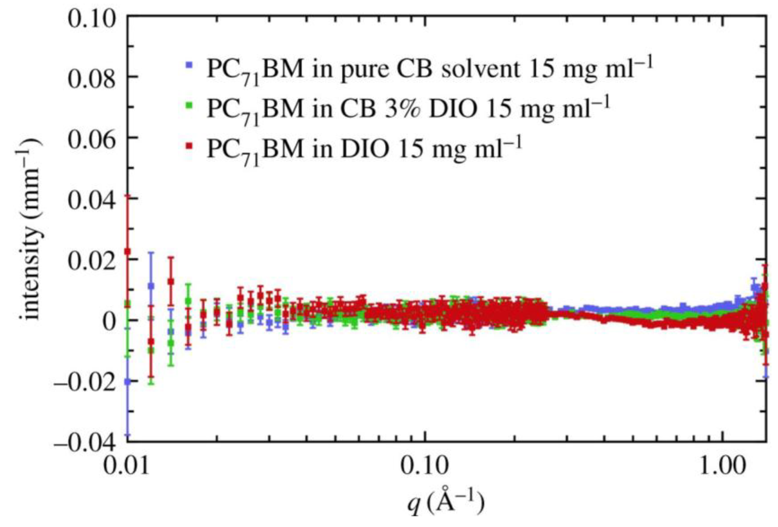
- Bernardo, G.; Washington, A.L.; Zhang, Y.; King, S.M.; Toolan, D.T.W.; Weir, M.P.; Dunbar, A.D.F.; Howse, J.R.; Dattani, R.; Fairclough, J.P.A.; et al. Does 1,8-diiodooctane affect the aggregation state of PC71BM in solution? R. Soc. Open Sci. 2018, 5, 180937. [Google Scholar] [CrossRef]
- Bernardo, G.; Washington, A.L.; Zhang, Y.; King, S.M.; Toolan, D.T.W.; Weir, M.P.; Dunbar, A.D.F.; Howse, J.R.; Dattani, R.; Fairclough, J.P.A.; et al. Data from: Does 1,8-Diiodooctane affect the aggregation state of PC71BM in solution? Dryad Dig. Repos. 2018. [Google Scholar] [CrossRef]
- Liang, Y.Y.; Xu, Z.; Xia, J.B.; Tsai, S.T.; Wu, Y.; Li, G.; Ray, C.; Yu, L.P. For the Bright Future-Bulk Heterojunction Polymer Solar Cells with Power Conversion Efficiency of 7.4%. Adv. Mater. 2010, 22, E135–E138. [Google Scholar] [CrossRef] [PubMed]
- Zhou, H.Q.; Zhang, Y.; Seifter, J.; Collins, S.D.; Luo, C.; Bazan, G.C.; Nguyen, T.Q.; Heeger, A.J. High-Efficiency Polymer Solar Cells Enhanced by Solvent Treatment. Adv. Mater. 2013, 25, 1646–1652. [Google Scholar] [CrossRef] [PubMed]
- He, Z.; Zhong, C.; Su, S.; Xu, M.; Wu, H.; Cao, Y. Enhanced power-conversion efficiency in polymer solar cells using an inverted device structure. Nat. Photonics 2012, 6, 591–595. [Google Scholar] [CrossRef]
- Li, M.; Zhang, W.; Tang, X.; Jin, J.; Wang, H.; Chen, L.; Lv, W.; Chen, R.; Huang, W. Bromine-Terminated Additives for Phase-Separated Morphology Control of PTB7:PC71BM-Based Polymer Solar Cells. ACS Sustain. Chem. Eng. 2017, 5, 11668–11675. [Google Scholar] [CrossRef]
- Oseni, S.O.; Mola, G.T. The effect of uni- and binary solvent additives in PTB7:PC61BM based solar cells. Sol. Energy 2017, 150, 66–72. [Google Scholar] [CrossRef]
- Zheng, Y.F.; Goh, T.; Fan, P.; Shi, W.; Yu, J.S.; Taylor, A.D. Toward Efficient Thick Active PTB7 Photovoltaic Layers Using Diphenyl Ether as a Solvent Additive. ACS Appl. Mater. Interfaces 2016, 8, 15724–15731. [Google Scholar] [CrossRef]
- Zheng, Y.; Wang, G.; Huang, D.; Kong, J.; Goh, T.; Huang, W.; Yu, J.; Taylor, A.D. Binary Solvent Additives Treatment Boosts the Efficiency of PTB7:PCBM Polymer Solar Cells to Over 9.5%. Sol. RRL 2018, 2, 1700144. [Google Scholar] [CrossRef]
- Zhao, X.; Xiang, J.; Liu, D.; Zhou, D.; Wang, G.; Zhou, G.; Alameh, K.; Ding, B.; Song, Q. Impact of alkyl chain length of 1,n-diiodoalkanes on PC71BM distribution in both bulk and air surface of PTB7:PC71BM film. Org. Electron. 2016, 37, 358–365. [Google Scholar] [CrossRef]
- Li, Y.; Xu, Z.; Zhao, S.; Huang, D.; Zhao, L.; Zhang, C.; Zhao, J.; Wang, P.; Zhu, Y. Enhanced carrier dynamics of PTB7:PC71BM based bulk heterojunction organic solar cells by the incorporation of formic acid. Org. Electron. 2016, 28, 275–280. [Google Scholar] [CrossRef]
- Chen, J.; Zhang, L.; Jiang, X.; Gao, K.; Liu, F.; Gong, X.; Chen, J.; Cao, Y. Using o-Chlorobenzaldehyde as a Fast Removable Solvent Additive during Spin-Coating PTB7-Based Active Layers: High Efficiency Thick-Film Polymer Solar Cells. Adv. Energy Mater. 2017, 7, 1601344. [Google Scholar] [CrossRef]
- Ciammaruchi, L.; Brunetti, F.; Visoly-Fisher, I. Solvent effects on the morphology and stability of PTB7:PCBM based solar cells. Sol. Energy 2016, 137, 490–499. [Google Scholar] [CrossRef]
- Dkhil, S.B.; Pfannmöller, M.; Saba, M.I.; Gaceur, M.; Heidari, H.; Videlot-Ackermann, C.; Margeat, O.; Guerrero, A.; Bisquert, J.; Garcia-Belmonte, G.; et al. Toward High-Temperature Stability of PTB7-Based Bulk Heterojunction Solar Cells: Impact of Fullerene Size and Solvent Additive. Adv. Energy Mater. 2017, 7, 1601486. [Google Scholar] [CrossRef]
- Bartesaghi, D.; Ye, G.; Chiechi, R.C.; Koster, L.J.A. Compatibility of PTB7 and [70]PCBM as a Key Factor for the Stability of PTB7:[70]PCBM Solar Cells. Adv. Energy Mater. 2016, 6, 1502338. [Google Scholar] [CrossRef]
- He, Y.J.; Shao, M.; Xiao, K.; Smith, S.C.; Hong, K.L. High-performance polymer photovoltaics based on rationally designed fullerene acceptors. Sol. Energy Mater. Sol. Cells 2013, 118, 171–178. [Google Scholar] [CrossRef]
- Karakawa, M.; Nagai, T.; Adachi, K.; Ie, Y.; Aso, Y. N-phenyl 60 fulleropyrrolidines: Alternative acceptor materials to PC61BM for high performance organic photovoltaic cells. J. Mater. Chem. A 2014, 2, 20889–20895. [Google Scholar] [CrossRef]
- Tseng, N.W.; Yu, Y.; Li, Y.K.; Zhao, J.B.; So, S.K.; Yan, H.; Ng, K.M. Isobenzofulvene-fullerene mono-adducts for organic photovoltaic applications. J. Mater. Chem. C 2015, 3, 977–980. [Google Scholar] [CrossRef]
- Huang, S.H.; Zhang, G.Y.; Knutson, N.S.; Fontana, M.T.; Huber, R.C.; Ferreira, A.S.; Tolbert, S.H.; Schwartz, B.J.; Rubin, Y. Beyond PCBM: Methoxylated 1,4-bisbenzyl 60 fullerene adducts for efficient organic solar cells. J. Mater. Chem. A 2016, 4, 416–424. [Google Scholar] [CrossRef]
- Nagarjuna, P.; Bagui, A.; Hou, J.H.; Singh, S.P. New Electron Acceptor Derived from Fluorene: Synthesis and Its Photovoltaic Properties. J. Phys. Chem. C 2016, 120, 13390–13397. [Google Scholar] [CrossRef]
- Nagarjuna, P.; Bagui, A.; Garg, A.; Gupta, V.; Singh, S.P. One-Step Synthesis of New Electron Acceptor for High Efficiency Solution Processable Organic Solar Cells. J. Phys. Chem. C 2017, 121, 26615–26621. [Google Scholar] [CrossRef]
- Roehling, J.D.; Baran, D.; Sit, J.; Kassar, T.; Ameri, T.; Unruh, T.; Brabec, C.J.; Moulé, A.J. Nanoscale Morphology of PTB7 Based Organic Photovoltaics as a Function of Fullerene Size. Sci. Rep. 2016, 6, 30915. [Google Scholar] [CrossRef] [PubMed] [Green Version]
- Cheng, P.; Li, Y.F.; Zhan, X.W. Efficient ternary blend polymer solar cells with indene-C-60 bisadduct as an electron-cascade acceptor. Energy Environ. Sci. 2014, 7, 2005–2011. [Google Scholar] [CrossRef]
- Ma, G.; Liu, Z.; Wang, N. Efficient ternary polymer solar cells with dihydronaphthyl-based C60 bisadduct as an third component material. Sol. Energy 2018, 170, 164–173. [Google Scholar] [CrossRef]
- Fernandes, L.; Gaspar, H.; Tome, J.P.C.; Figueira, F.; Bernardo, G. Thermal stability of low-bandgap copolymers PTB7 and PTB7-Th and their bulk heterojunction composites. Polym. Bull. 2018, 75, 515–532. [Google Scholar] [CrossRef]
- Zhang, S.Q.; Ye, L.; Zhao, W.C.; Liu, D.L.; Yao, H.F.; Hou, J.H. Side Chain Selection for Designing Highly Efficient Photovoltaic Polymers with 2D-Conjugated Structure. Macromolecules 2014, 47, 4653–4659. [Google Scholar] [CrossRef]
- Huang, W.C.; Gann, E.; Thomsen, L.; Dong, C.K.; Cheng, Y.B.; McNeill, C.R. Unraveling the Morphology of High Efficiency Polymer Solar Cells Based on the Donor Polymer PBDTTT-EFT. Adv. Energy Mater. 2015, 5, 11. [Google Scholar] [CrossRef]
- Wan, Q.; Guo, X.; Wang, Z.; Li, W.; Guo, B.; Ma, W.; Zhang, M.; Li, Y. 10.8% Efficiency Polymer Solar Cells Based on PTB7-Th and PC71BM via Binary Solvent Additives Treatment. Adv. Funct. Mater. 2016, 26, 6635–6640. [Google Scholar] [CrossRef]
- Fan, R.; Huai, Z.X.; Sun, Y.S.; Li, X.W.; Fu, G.S.; Huang, S.H.; Wang, L.X.; Yang, S.P. Enhanced performance of polymer solar cells based on PTB7-Th: PC71BM by doping with 1-bromo-4-nitrobenzene. J. Mater. Chem. C 2017, 5, 10985–10990. [Google Scholar] [CrossRef]
- Jagadamma, L.K.; Sajjad, M.T.; Savikhin, V.; Toney, M.F.; Samuel, I.D.W. Correlating photovoltaic properties of a PTB7-Th:PC71BM blend to photophysics and microstructure as a function of thermal annealing. J. Mater. Chem. A 2017, 5, 14646–14657. [Google Scholar] [CrossRef]
- Kobori, T.; Fukuda, T. Effect of optical intensity distribution on device performances of PTB7-Th:PC71BM-based organic photovoltaic cells. Org. Electron. 2017, 51, 76–85. [Google Scholar] [CrossRef]
- Jain, N.; Chandrasekaran, N.; Sadhanala, A.; Friend, R.H.; McNeill, C.R.; Kabra, D. Interfacial disorder in efficient polymer solar cells: The impact of donor molecular structure and solvent additives. J. Mater. Chem. A 2017, 5, 24749–24757. [Google Scholar] [CrossRef]
- Pearson, A.J.; Hopkinson, P.E.; Couderc, E.; Domanski, K.; Abdi-Jalebi, M.; Greenham, N.C. Critical light instability in CB/DIO processed PBDTTT-EFT:PC71BM organic photovoltaic devices. Org. Electron. 2016, 30, 225–236. [Google Scholar] [CrossRef]
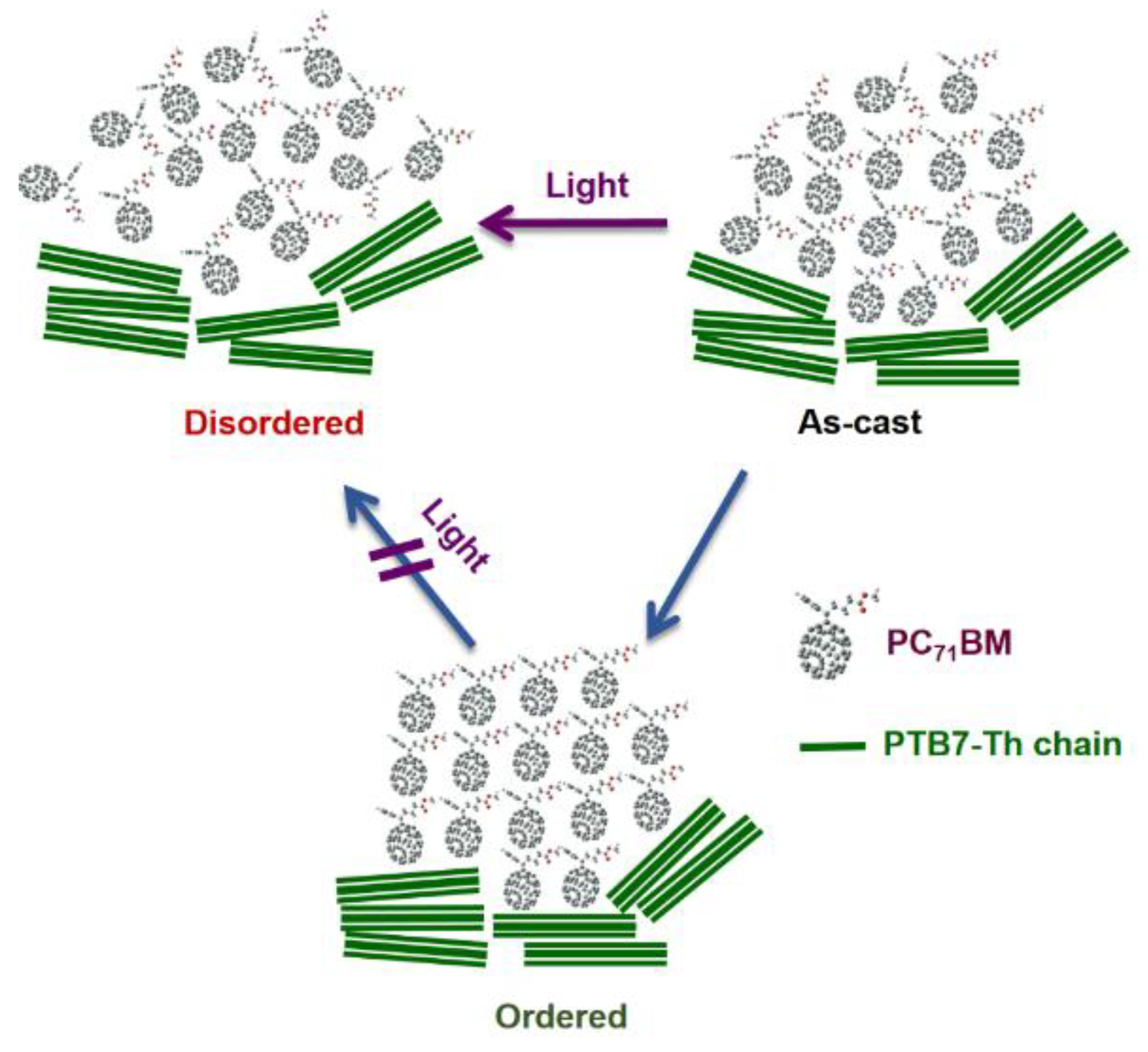
- Liu, Q.; Toudert, J.; Liu, F.; Mantilla-Perez, P.; Bajo, M.M.; Russell, T.P.; Martorell, J. Circumventing UV Light Induced Nanomorphology Disorder to Achieve Long Lifetime PTB7-Th:PCBM Based Solar Cells. Adv. Energy Mater. 2017, 7, 1701201. [Google Scholar] [CrossRef]
- Huang, W.C.; Gann, E.; Chandrasekaran, N.; Prasad, S.K.K.; Chang, S.Y.; Thomsen, L.; Kabra, D.; Hodgkiss, J.M.; Cheng, Y.B.; Yang, Y.; et al. Influence of Fullerene Acceptor on the Performance, Microstructure, and Photophysics of Low Bandgap Polymer Solar Cells. Adv. Energy Mater. 2017, 7, 10. [Google Scholar] [CrossRef]
- Zhang, C.H.; Langner, S.; Mumyatov, A.V.; Anokhin, D.V.; Min, J.; Perea, J.D.; Gerasimov, K.L.; Osvet, A.; Ivanov, D.A.; Troshin, P.; et al. Understanding the correlation and balance between the miscibility and optoelectronic properties of polymer-fullerene solar cells. J. Mater. Chem. A 2017, 5, 17570–17579. [Google Scholar] [CrossRef]
- Nagarjuna, P.; Bagui, A.; Gupta, V.; Singh, S.P. A highly efficient PTB7-Th polymer donor bulk hetero-junction solar cell with increased open circuit voltage using fullerene acceptor CN-PC70BM. Org. Electron. 2017, 43, 262–267. [Google Scholar] [CrossRef]
- Liu, Y.; Zhao, J.; Li, Z.; Mu, C.; Ma, W.; Hu, H.; Jiang, K.; Lin, H.; Ade, H.; Yan, H. Aggregation and morphology control enables multiple cases of high-efficiency polymer solar cells. Nat. Commun. 2014, 5, 5293. [Google Scholar] [CrossRef] [Green Version]
- Ma, W.; Yang, G.; Jiang, K.; Carpenter Joshua, H.; Wu, Y.; Meng, X.; McAfee, T.; Zhao, J.; Zhu, C.; Wang, C.; et al. Influence of Processing Parameters and Molecular Weight on the Morphology and Properties of High-Performance PffBT4T-2OD:PC71BM Organic Solar Cells. Adv. Energy Mater. 2015, 5, 1501400. [Google Scholar] [CrossRef]
- Zhang, X.; Zheng, D.; Xing, S.; Wang, H.; Huang, J.; Yu, J. Precisely control the morphology and crystallization of temperature-dependent aggregation bulk heterojunction by using co-solvent system for optimized light intensity distribution and its effect on thick active layer polymer solar cells. Sol. Energy 2017, 147, 106–112. [Google Scholar] [CrossRef]
- Zhao, J.; Zhao, S.; Xu, Z.; Qiao, B.; Huang, D.; Zhao, L.; Li, Y.; Zhu, Y.; Wang, P. Revealing the Effect of Additives with Different Solubility on the Morphology and the Donor Crystalline Structures of Organic Solar Cells. ACS Appl. Mater. Interfaces 2016, 8, 18231–18237. [Google Scholar] [CrossRef]
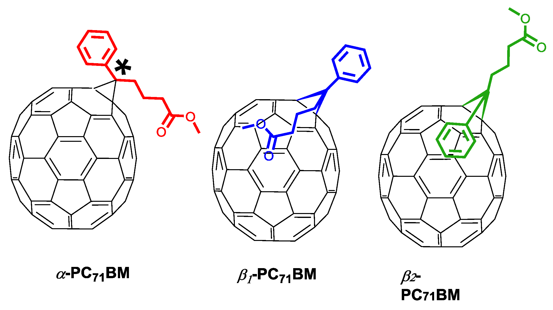
- Umeyama, T.; Igarashi, K.; Sakamaki, D.; Seki, S.; Imahori, H. Unique cohesive nature of the [small beta]1-isomer of [70]PCBM fullerene on structures and photovoltaic performances of bulk heterojunction films with PffBT4T-2OD polymers. Chem. Commun. 2018, 54, 405–408. [Google Scholar] [CrossRef] [PubMed]
- Vidal, S.; Izquierdo, M.; Law, W.K.; Jiang, K.; Filippone, S.; Perles, J.; Yan, H.; Martin, N. Photochemical site-selective synthesis of [70]methanofullerenes. Chem. Commun. 2016, 52, 12733–12736. [Google Scholar] [CrossRef] [PubMed] [Green Version]
- Li, W.; Cai, J.; Cai, F.; Yan, Y.; Yi, H.; Gurney, R.S.; Liu, D.; Iraqi, A.; Wang, T. Achieving over 11% power conversion efficiency in PffBT4T-2OD-based ternary polymer solar cells with enhanced open-circuit-voltage and suppressed charge recombination. Nano Energy 2018, 44, 155–163. [Google Scholar] [CrossRef]
- Zhang, Y.; Parnell, A.J.; Blaszczyk, O.; Musser, A.J.; Samuel, I.D.W.; Lidzey, D.G.; Bernardo, G. Effect of fullerene acceptor on the performance of solar cells based on PffBT4T-2OD. Phys. Chem. Chem. Phys. 2018, 20, 19023–19029. [Google Scholar] [CrossRef] [PubMed]


| Acceptor | D:A Wt. | Solvent | Additive | JSC (mA cm−2) | VOC (V) | FF (%) | PCE (%) Best (average) | Device Structure | Device Area (mm2) | Obs. | Ref |
|---|---|---|---|---|---|---|---|---|---|---|---|
| PC71BM | 1:1.5 | CB (100 vol %) | ------- | 10.20 | 0.76 | 50.52 | 3.92 | Standard ITO/PEDOT:PSS/BHJ/Ca/Al | 10.0 | ---- | [85] |
| CB (97 vol %) | DIO (3 vol %) | 14.50 | 0.74 | 68.97 | 7.40 | ||||||
| PC71BM | 1:1.5 | CB (97 vol %) | DIO (3 vol %) | 15.46 | 0.76 | 68 ± 1 | 7.94 | Standard ITO/PEDOT:PSS/BHJ/Ca/Al | 4.5 | (a) | [86] |
| PC71BM | 1:1.5 | o-DCB (100 vol %) | ------- | 18.51 | 0.76 | 60 | 8.50 | Standard ITO/PEDOT:PSS/BHJ/Ca/Al | 4.5 | (b) | [71] |
| PC71BM | 1:1.5 | CB (97 vol %) | DIO (3 vol %) | 15.4 | 0.759 | 70.6 | 8.24 | Standard ITO/PEDOT:PSS/BHJ/PFN/Ca/Al | 16 | (c) | [87] |
| 17.2 | 0.740 | 72.0 | 9.15 | Inverted ITO/PFN/BHJ/MoO3/Al | |||||||
| PC71BM | 1:1.5 | CB (100 vol %) | ------- | 11.43 | 0.70 | 46 | 3.99 (3.68) | Standard ITO/PEDOT:PSS/BHJ/Ca/Al | 7.5 | (d) | [61] |
| CB (97 vol %) | SH-na (3 vol %) | 15.67 | 0.79 | 70 | 8.75 (8.42) | Standard ITO/PEDOT:PSS/BHJ/Ca/Al | |||||
| PC71BM | 1:1.5 | CB (95 vol %) | DPE (2 vol %)+ DIO (3 vol %) | 18.1 | 0.72 | 71.0 | 9.55 (9.25) | Inverted ITO/ZnO/BHJ/MoO3/Ag | ----- | ---- | [91] |
| PC71BM | 1:1.5 | CB 97 vol % | DIO 3 vol % | 17.49 | 0.764 | 66.1 | 8.84 | Inverted ITO/PEIE/BHJ/MoO3/Ag | 9 | ---- | [92] |
| PC71BM | 1:1.5 | CB (91 vol %) | FA (6 vol %) + DIO (3 vol %) | 24.11 | 0.72 | 52.11 | 9.04 | Standard ITO/PEDOT:PSS/BHJ/Li/Al | 4 | (e) | [93] |
| PC71BM | 1:1.5 | CB (97 vol %) | DIO (3 vol %) | 15.2 | 0.73 | 67.8 | 7.53 (7.40) | Standard ITO/PEDOT:PSS/BHJ/PFN/Al | 16 | ---- | [94] |
| CB (95 vol %) | CBA (5 vol %) | 16.7 | 0.75 | 73.0 | 9.11 (8.99) | Standard ITO/PEDOT:PSS/BHJ/PFN/Al | |||||
| PC71BM | 1:1.5 | o-DCB (97 vol %) | DIO (3 vol %) | 14.2 | 0.74 | 60.0 | 6.30 | Standard ITO/PEDOT:PSS/BHJ/Ca/Al | 10 | ---- | [98] |
| ICBM | 15.4 | 0.79 | 55.0 | 6.67 | |||||||
| Fullerene 4 | 1:1.5 | CB (97 vol %) | DIO (3 vol %) | 15.48 | 0.749 | 63.3 | 7.34 | Inverted ITO/PFN/BHJ/MoOx/Al | 9 | ---- | [99] |
| Fullerene 5 | 14.21 | 0.760 | 67.3 | 7.27 | |||||||
| Fullerene 6 | 14.03 | 0.797 | 61.0 | 6.83 | |||||||
| PC61BM | 14.29 | 0.740 | 66.5 | 7.03 | |||||||
| IC60MA-2C | ----- | CB (97 vol %) | DIO (3 vol %) | 14.2 | 0.77 | 55 | 6.0 | Inverted ITO/ZnO/BHJ/MoO3/Al | 7 | ---- | [100] |
| IC60MA-3C | 12.9 | 0.79 | 50 | 5.1 | |||||||
| IC60MA-4C | 13.7 | 0.77 | 61 | 6.5 | |||||||
| PC61BM | 14.6 | 0.76 | 62 | 6.8 | |||||||
| Fullerene 1e | 1:1.5 | CB 95 vol % | DIO 5 vol % | 12.3 | 0.825 | 53.3 | 5.4 | Standard ITO/PEDOT:PSS/BHJ/Ca/Al | 7.2 | ---- | [101] |
| PC61BM | 12.1 | 0.760 | 64.4 | 5.9 | |||||||
| Fullerene N3 | 1:1.5 | o-DCB 97 vol % | DIO 3 vol % | 9.73 | 0.812 | 52.1 | 4.12 | Inverted ITO/ZnO/BHJ/MoO3/Ag | ----- | ---- | [102] |
| Fullerene N6 | 9.06 | 0.805 | 50.2 | 3.64 | |||||||
| DIF-ful-C60 | 1:1.5 | o-DCB 97 vol % | DIO 3 vol % | 15.97 | 0.82 | 51 | 6.8 (6.5) | Inverted ITO/ZnO/BHJ/MoO3/Ag | ----- | (f) | [103] |
| PC61BM | 15.40 | 0.70 | 58 | 6.2 (5.9) | |||||||
| PC71BM | 1:1.5 | CB (97 vol %) | DIO (3 vol %) | 14.99 | 0.701 | 68.8 | 7.35 (7.23) | Standard ITO/PEDOT:PSS/BHJ/Ca/Al | 4 | ---- | [105] |
| PC71BM(85%) + ICBA (15%) | 16.32 | 0.720 | 69.2 | 8.24 (8.13) | |||||||
| PC71BM | 1:1.5 | o-DCB (97 vol %) | DIO (3 vol %) | 17.4 | 0.76 | 64.8 | 8.57 | Inverted ITO/ZnO/BHJ/MoO3/Ag | 9 | ---- | [106] |
| PC71BM (85%) + NCBA (15%) | 18.6 | 0.78 | 67.9 | 9.85 |
| Acceptor | D:A (w/w) | Solvent | Additive | JSC (mA cm−2) | VOC (V) | FF (%) | PCE (%) Best (average) | Device Structure | Device Area (mm2) | Obs. | Ref. |
|---|---|---|---|---|---|---|---|---|---|---|---|
| PC71BM | 1:1.5 | o-DCB (99 vol %) | DIO (1 vol %) | 16.03 | 0.786 | 65.12 | 8.21 | Standard ITO/PEDOT:PSS/BHJ/Ca/Al | 4 | ---- | [108] |
| o-DCB (97 vol %) | DIO (3 vol %) | 16.86 | 0.784 | 68.16 | 9.00 | ||||||
| o-DCB (95 vol %) | DIO (5 vol %) | 14.59 | 0.779 | 64.73 | 7.35 | ||||||
| PC71BM | 1:1.5 | CB (100 vol %) | --------- | 16.2 | 0.80 | 49 | 6.4 (6.1) | Inverted ITO/PEIE/BHJ/MoO3/Ag | 4.5 | ---- | [109] |
| CB (97 vol %) | DIO (3 vol %) | 18.1 | 0.79 | 66 | 9.5 (9.3) | ||||||
| PC71BM | 1:1.5 | o-DCB (100 vol %) | --------- | 17.0 | 0.83 | 58.1 | 8.2 (8.1) | Standard ITO/PEDOT:PSS/BHJ/C60-N/Al | 4 | (a) | [110] |
| o-DCB (97 vol %) | NMP (3 vol %) | 18.0 | 0.82 | 62.1 | 9.2 (8.9) | ||||||
| o-DCB (97 vol %) | DIO (3 vol %) | 17.9 | 0.82 | 64.5 | 9.5 (9.2) | ||||||
| o-DCB (97 vol %) | DIO 1.5 vol % + NMP 1.5 vol % | 19.1 | 0.82 | 69.1 | 10.8 (10.4) | ||||||
| PC71BM | 1:1.5 | CB (97 vol %) | DIO (3 vol %) | 15.97 | 0.79 | 60.12 | 7.58 (7.51) | ITO/PEDOT:PSS/BHJ/BCP/Ag | 12.56 | (b) | [111] |
| 17.74 | 0.784 | 64.11 | 8.95 (8.89) | ||||||||
| PC71BM | 1:0.5 | o-DCB (100 vol %) | --------- | 6.69 | 0.78 | 31 | 1.60 | Standard ITO/PEDOT:PSS/BHJ/Ca/Al | 13 | (c) | [62] |
| 1:1 | 12.59 | 0.80 | 50 | 5.04 | |||||||
| 1:1.5 | 19.01 | 0.80 | 53 | 8.08 | |||||||
| 1:2 | 18.15 | 0.79 | 65 | 9.38 | |||||||
| 1:3 | 10.41 | 0.77 | 43 | 3.49 | |||||||
| PC71BM (0.45 wt) + COi8DFIC (1.05 wt) | 1:1.5 | CB (99 vol %) | DIO (1 vol %) | 28.20 | 0.70 | 71.0 | 14.08 | Inverted ITO/ZnO/BHJ/MoO3/Ag | 4 | ---- | [7] |
| PC71BM | 1:1.5 | CB (97 vol %) | DIO (3 vol %) | 16.6 | 0.77 | 71.3 | 9.1 (8.8) | Inverted ITO/ZnO/BHJ/MoO3/Ag | 8 | (d) | [112] |
| PC71BM | 1:1.5 | o-DCB (97 vol %) | DIO (3 vol %) | 16.55 | 0.80 | 71 | 9.68 (9.42) | Inverted ITO/ZnO/BHJ/MoO3/Ag | ---- | (e) | [59] |
| 1:3 | 14.53 | 0.80 | 73 | 8.73 (8.51) | |||||||
| PC71BM | 1:1.8 | CB (97 vol %) | DIO (3 vol %) | ---- | ---- | ---- | 9.25 | Standard ITO/PEDOT:PSS/BHJ/LiF/Al | 8 | (f) | [113] |
| ---- | ---- | ---- | 10.4 | Inverted ITO/ZnO/BHJ/MoO3/Ag | |||||||
| PC71BM | 1:1.5 | CB (100 vol %) | --------- | 9.7 | 0.83 | 47.5 | 3.8 (3.3) | Inverted ITO/PEIE/BHJ/MoO3/Ag | ---- | ---- | [114] |
| CB (97 vol %) | DIO (3 vol %) | 16.1 | 0.79 | 64.8 | 8.3 (8.1) | ||||||
| PC71BM | 1:1.5 | CB (97 vol %) | DIO (3 vol %) | Standard ITO/PEDOT:PSS/BHJ/Ca/Ag | 4.5 | ---- | [115] | ||||
| Inverted ITO/TiO2/BHJ/MoOx/Ag | |||||||||||
| PC71BM | 1:1.5 | CB (97 vol %) | DIO (3 vol %) | 16.85 | 0.801 | 70.27 | 9.72 (9.49) | Inverted ITO/ZnO/BHJ/MoO3/Ag | 6 | ---- | [116] |
| 1:1.5 | 1,2-DCB (100 vol %) | ----------- | 14.93 | 0.802 | 65.28 | 7.82 | Inverted ITO/PFN/BHJ/MoO3/Ag | ||||
| 1:2.0 | 16.01 | 0.802 | 72.28 | 9.59 (9.28) | |||||||
| PC61BM | 1:1.5 | CB (97 vol %) | DIO (3 vol %) | 14.6 | 0.81 | 64 | (7.6) | Inverted ITO/PEIE/BHJ/MoO3/Ag | 10 | ---- | [117] |
| PC71BM | 17.7 | 0.80 | 66 | (9.4) | |||||||
| ICBA | 13.3 | 1.0 | 53 | (7.1) | |||||||
| PC61BM | 1:1.5 | CB (97 vol %) | DIO (3 vol %) | 14.0 | 0.80 | 65 | 7.3 | Inverted ITO/ZnO/BHJ/MoOx/Ag | 10.4 | (g) | [118] |
| PyF5 | 1:2 | 13.7 | 0.84 | 56 | 6.5 | ||||||
| FAP1 | 1:2 | 12.7 | 0.87 | 55 | 6.1 | ||||||
| PC61BM | 1:1.5 | o-DCB (97 vol %) | DIO (3 vol %) | 15.14 | 0.84 | 62 | 7.9 (7.7) | Inverted ITO/ZnO/BHJ/MoO3/Ag | ---- | ---- | [103] |
| DIF-ful-C60 | 16.01 | 0.82 | 65 | 8.6 (8.4) | |||||||
| PC71BM | 1:1.5 | CB (97 vol %) | CLN (3 vol %) | 14.0 | 0.795 | 48.8 | 5.4 | Inverted ITO/ZnO/BHJ/MoO3/Ag | 10 | ---- | [119] |
| CN-PC71BM | 13.5 | 0.898 | 68.0 | 8.2 |
| Acceptor | D:A (w/w) | Solvent | Additive | JSC (mA cm−2) | VOC (V) | FF (%) | PCE (%) Best (Average) | Device Structure | Device Area (mm2) | Obs. | Ref. |
|---|---|---|---|---|---|---|---|---|---|---|---|
| PC71BM | 1:1.2 | CB (48.5 vol %) + DCB (48.5 vol %) | DIO (3 vol %) | 18.5 | 0.79 | 71 | 10.3 | Inverted ITO/ZnO/BHJ/MoO3/Al | 5.64 | (a) | [121] |
| PC71BM | 1:1.2 | CB (48.5 vol %) + DCB (48.5 vol %) | DIO (3 vol %) | 18.19 | 0.76 | 66.6 | 9.16 (9.07) | Inverted ITO/ZnO/BHJ/MoO3/Ag | 2 | (b) | [122] |
| PC71BM | 1:1.3 | CB (48.5 vol %) + DCB (48.5 vol %) | CLN (3 vol %) | 17.75 | 0.79 | 73.1 | 10.23 best | Standard ITO/PEDOT:PSS/BHJ/LiF/Al | 4 | (c) | [123] |
| PC71BM | 1:1.2 | CB (50 vol %) + DCB (50 vol %) | ----------- | 16.13 | 0.72 | 62.93 | 7.29 (7.08) | Standard ITO/PEDOT:PSS/BHJ/Ca/Al | 2.6 | (d) | [39] |
| CB (48.5 vol %) + DCB (48.5 vol %) | DIO (3 vol %) | 17.33 | 0.75 | 68.34 | 8.90 (8.73) | ||||||
| PC71BM | ------ | CB (48.5 vol %) + DCB (48.5 vol %) | DIO (3 vol %) | 19.5 | 0.75 | 72.2 | 10.57 (10.3) | Inverted ITO/TiO2/BHJ/MoO3/Ag | ----- | (e) | [126] |
| 18.8 | 0.79 | 74.7 | 11.17 (11.0) | ||||||||
| TC71BM | 1:1.2 | CB (48.5 vol %) + DCB (48.5 vol %) | DIO (3 vol %) | 18.8 | 0.77 | 75 | 10.8 (10.3) | Inverted ITO/ZnO/BHJ/MoO3/Al | 5.9 | ----- | [120] |
| PC71BM | 18.4 | 0.77 | 74 | 10.5 (10.2) | |||||||
| PC61PM | 17.7 | 0.77 | 76 | 10.4 (10.1) | |||||||
| ICMA | 16.4 | 0.78 | 77 | 9.8 (9.4) | |||||||
| TC61PM | 17.4 | 0.75 | 74 | 9.7 (9.3) | |||||||
| PC61BM | 17.1 | 0.77 | 73 | 9.6 (9.3) | |||||||
| PC71BM | 1:1.2 | CB (48.5 vol %) + DCB (48.5 vol %) | DIO (3 vol %) | 17.3 | 0.76 | 70 | 9.31 (8.93) | Standard ITO/PEDOT:PSS/BHJ/Ca/Al | 2.6 | ----- | [127] |
| PC61BM | 16.3 | 0.77 | 67 | 8.46 (8.15) | |||||||
| ICBA | 7.5 | 0.94 | 45 | 3.19 (2.78) |
© 2018 by the authors. Licensee MDPI, Basel, Switzerland. This article is an open access article distributed under the terms and conditions of the Creative Commons Attribution (CC BY) license (http://creativecommons.org/licenses/by/4.0/).
Share and Cite
Gaspar, H.; Figueira, F.; Pereira, L.; Mendes, A.; Viana, J.C.; Bernardo, G. Recent Developments in the Optimization of the Bulk Heterojunction Morphology of Polymer: Fullerene Solar Cells. Materials 2018, 11, 2560. https://doi.org/10.3390/ma11122560
Gaspar H, Figueira F, Pereira L, Mendes A, Viana JC, Bernardo G. Recent Developments in the Optimization of the Bulk Heterojunction Morphology of Polymer: Fullerene Solar Cells. Materials. 2018; 11(12):2560. https://doi.org/10.3390/ma11122560
Chicago/Turabian StyleGaspar, Hugo, Flávio Figueira, Luiz Pereira, Adélio Mendes, Júlio C. Viana, and Gabriel Bernardo. 2018. "Recent Developments in the Optimization of the Bulk Heterojunction Morphology of Polymer: Fullerene Solar Cells" Materials 11, no. 12: 2560. https://doi.org/10.3390/ma11122560
APA StyleGaspar, H., Figueira, F., Pereira, L., Mendes, A., Viana, J. C., & Bernardo, G. (2018). Recent Developments in the Optimization of the Bulk Heterojunction Morphology of Polymer: Fullerene Solar Cells. Materials, 11(12), 2560. https://doi.org/10.3390/ma11122560