4.2. Tensile Properties of DB Propellants
Table 1 shows the tensile performances of blank DB propellant (A) and PTFE-DB propellant (P6). The mechanical properties of the two artificial aged propellants were also determined as shown in
Table 1. The typical stress-strain curves of the two propellants can be found in
Figure S3 in supporting information. It is well known that DB propellant is brittle at low temperature due to the frozen rigid NC molecules. This is a fatal drawback of DB propellant restricting its application field. Generally, elongation of DB propellants at −40 °C largely depends on the mass ratio of NC/NG [
1,
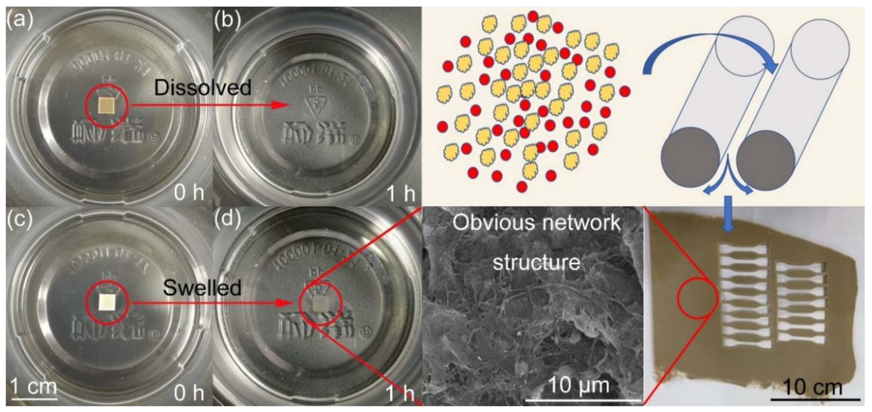
2]. In this paper, elongation at maximum strength of propellant A is only 6.34% at −40 °C. This is mainly due to the relatively lower NG concentration. However, it is quite different for PTFE-DB propellant. The elongation of PTFE-DB propellant was enhanced by 115% to 13.6%. In addition, the tensile strength was increased by 71.0% from 3.28 MPa to 5.61 MPa. Both strength and elongation were improved obviously. This is of practical importance for potential broadening the application field of DB propellant. PTFE deformed to “network structure” during process of propellant (see in
Figure 1). Thus, this promotion of propellant mechanical performance is mainly caused by the PTFE network structure since many works [
33,
36] have shown improved strength due to this kind of network.
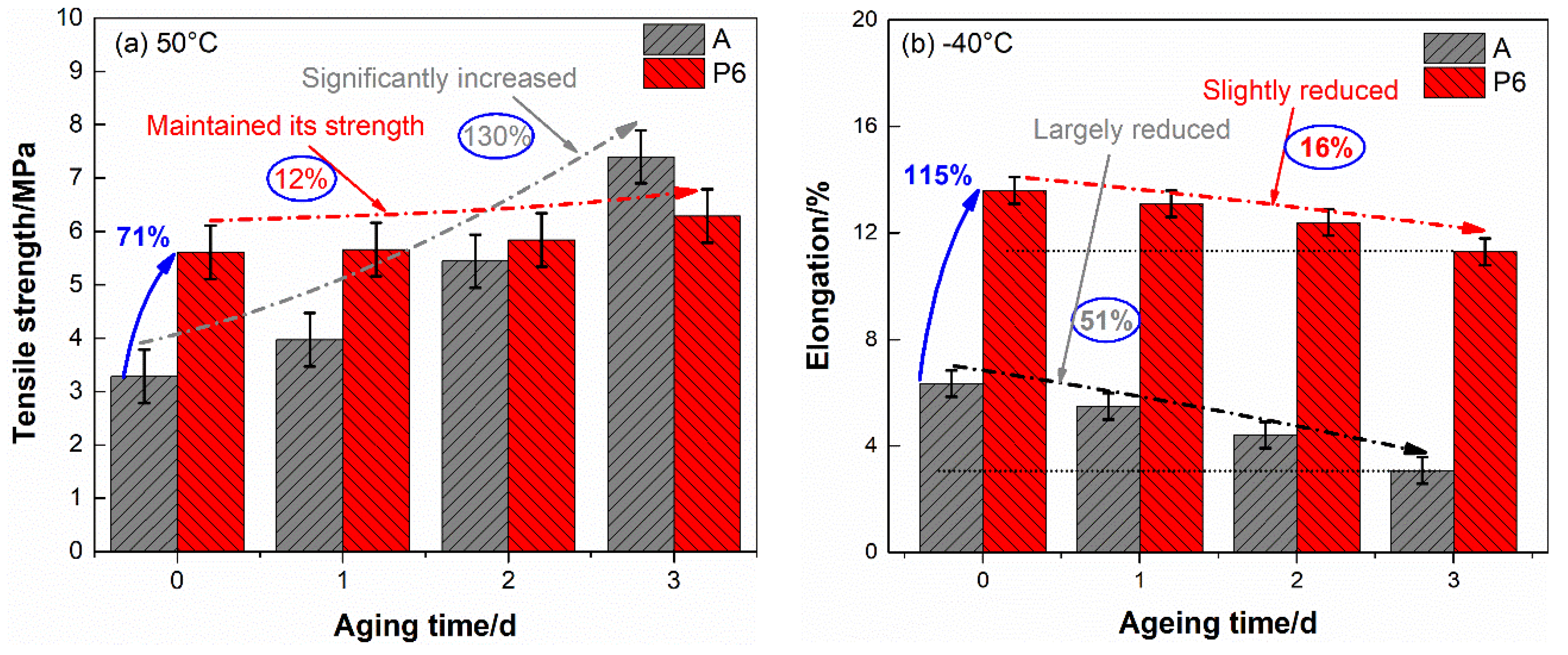
After aged, the tensile properties of the two propellants reduced to some extent. To achieve the trend of these alteration clearly, the most concerned tensile strength at 50 °C and elongation at −40 °C were drawn in
Figure 2 as a function of aging time.
From
Table 1 and
Figure 2 we can see that the mechanical properties of blank DB propellant are sensitive to aging time. The tensile strength and elongation present opposite trend along with aging of propellant. The tensile strength at 50 °C increased by 130% after aged three days, accompanied by a 43.1% reduction in the elongation. In addition, the elongation at −40 °C decreased by 51.4% to a very low level (3.08%). In view of the complex loadings in handling, transportation and launch mission, such a low elongation leads to structural failure readily, which may result in deadly accident in rocket motors. This is largely responsible for much decreased actual service lifetime than theoretical predicted safe storage life for DB propellant grain.
As for PTFE-DB propellant, the tensile strength at 50 °C and elongation at −40 °C after aged three days are 6.29 MPa and 11.4%, respectively. This means that the tensile strength maintained its level even after aged three days. Though the elongation at −40 °C slightly decreased by 16.2%, it is still at a high level which is even significantly superior than unaged DB propellant.
Some principal mechanisms [
7] may involve in the chemical changes that associated with mechanical performance of DB propellant along with aging. (1) Cross-linking hardening occurred and a three-dimensional (3D) structure was developed. During aging the decomposition of NC and NG could occur since they are intrinsic instable. Then many kinds of radicals were produced and they reacted in a complicated way [
8]. Chain termination reaction may occur between alkoxyl radicals or the radicals of its ramification in this process, resulting in cross-linking between NC binder molecules. The followed elimination of free volume and inhibition of segmental rotation could introduce an increase in both modulus and T
g. (2) Concentration profile of nitroglycerine changed. This may be due to the diffusion of NG from propellant center to its surface, as well as NG evaporation and decomposition. This reduction could also result in increasing in modulus and T
g; (3) Break of NC chain resulted in a reduction in its molecular weight. The depolymerization process could lead to decreasing in modulus and T
g due to the so called “self-plasticization” effects. Both (1) and (2) would result in the increase of tensile strength and reduction of elongation, while (3) would lead to opposite results. In view of the aged samples in this paper are relatively thin (2 mm), the decline of NG content may be the key factor contribute to the changes of propellant mechanical properties.
To verify this view, low field nuclear magnetic resonance was used to determine the crosslinking density of DB propellant as shown in
Figure S4. No obvious alternation (very slightly increased) of crosslinking density can be found for DB and PTFE-DB propellant. Thus, rare 3D structures were formed during aging. It proves that crosslinking is not a main factor leading to obvious decline of propellant mechanical properties. In addition, the molecular weight between crosslinking points varies little. This infers that there is no obvious break of NC chains as well. Thus, no obvious reduction in tensile strength was obtained due to depolymerization of binder.
Besides, the reduction of NG content was determined via a mass loss way. The results are shown in
Table S1 in supporting information. It can be found that the NG concentration reduced by 25.6% after aged 3 days for DB propellant. That is to say large amount of NG lost through evaporation. While it decreased by 14.0% for NG in PTFE-DB propellant. Thereby the NG content obvious differs between these two aged propellants, which would lead to different trend of mechanical properties to aging time. It is worth noting that a 14.0% reduction could also lead to obvious decline of propellant mechanical properties. However, the greatly enhanced performance is largely depending on the strong network structure. And it may be free of the influence caused by NG reduction since PTFE is stable to most of solvents. Thus, the mechanical performances were maintained for PTFE-DB propellant.
Based on mentioned above, we can conclude that (1) little three-dimensional structure was developed and little break of NC chain occurred in a relatively short aging time for both DB and PTFE-DB propellant. (2) a great deal of NG volatilized for the DB propellant sample with thick of 2 mm. Thereby, the alteration of mechanical properties of DB propellant depends on the reduction in NG content during aging. Largely reduced plasticizer decreased the free volume and inhibited the movement of NC chain segment. Thus, the tensile strength at 50 °C increased while the elongation decreased. (3) NG loss was largely reduced for PTFE-DB propellant. The strong network structure and decreased loss of plasticizer delayed the decline of propellant properties.
In a word, the mechanical properties and its stability is largely promoted due to PTFE. The improved performance may reduce the possibility of structural failure, which, as a consequence, is likely to prolong the practical application lifetime.
Though the conclusion that PTFE-DB propellant has a relatively lower volatilization is drawn, the molecular motion characteristics of NG in DB matrix is unknown. To investigate the influence of PTFE on NG diffusivity, thermal analysis was carried out as follows.
4.4. Kinetics of NG Evaporation
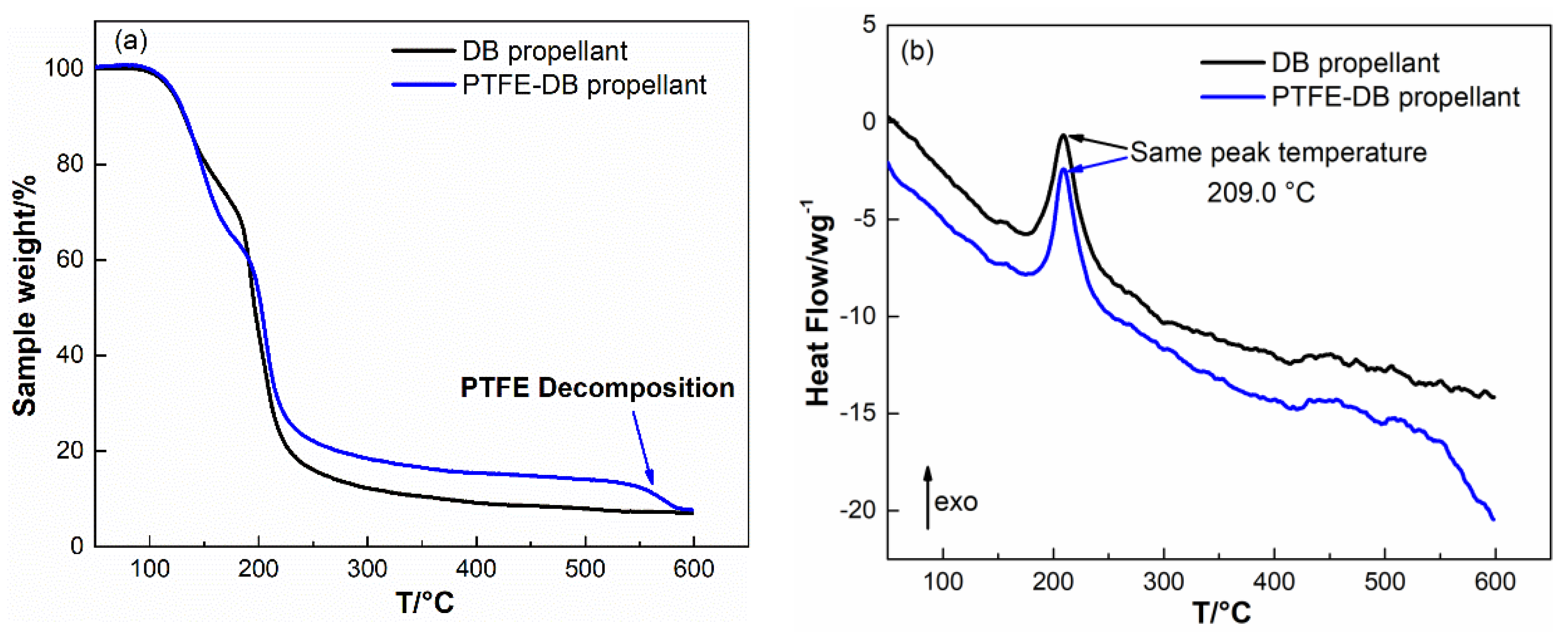
Thin plate samples with normalized size were heated at 50–100 °C with increment of 10 °C to investigate the kinetics of NG evaporation. The TGA results are shown in
Figure 4.
The obtained sample mass vs. time curve were converted to the conversion (α) vs. time according to Equation (1) [
29]:
where m
0 is the initial sample mass, m
f is the final sample mass (NG completely evaporated), and m
t is the instantaneous sample mass.
Then the obtained α were differentiated to time and plotted vs. α as shown in
Figure 5. In view of the early stage evaporation of NG in thin piece samples has been proved agree with zero order model, the curve of dα/dt vs. α could be described by the basic kinetic equation as Equation (2)
where k
vap is the evaporation rate constant, and f(α) is the function which describes the dependence of the differential conversion on conversion. In the case of plasticizer evaporation from double base propellant, f(α) could be simplified as (1 − α)
n meaning Equation (3) [
22,
31,
37]:
It is worth noting that the exponent n is influenced by the sample size and shape, thus, the normalized sample size and shape was used in isothermal thermogravimetry analysis. To reduce the influence of variation in NG concentration on the evaporation process, the α was limited to 0.2 during fitting to Equation (3).
The values of evaporation rate constant (k
vap) achieved by fitting to Equation (3) are shown in
Table 2.
From
Table 2 we can see that the k
vap of NG in PTFE-DB propellants is slightly less than that in DB propellants under the same temperature. It means that the evaporation of NG may be partly suppressed by PTFE. To determine the influence of PTFE on evaporation of NG, Arrhenius plots (ln k
vap vs. l/T) with good linearity was used to calculate the active energy of evaporation. The plots of DB and PTFE-DB propellants are shown in
Figure 6. The obtained kinetic parameters are shown in
Table 3.
For DB propellant: E
vap = 80.1 kJ·mol
−1 and A
vap = 2.50 × 10
9 s
−1, while for PTFE-DB propellant: E
vap = 83.0 kJ·mol
−1 and A
vap = 2.19 × 10
9 s
−1. The determined activation energy of NG evaporation in DB propellant is close to the results of Sućeska [
22]. The E
vap for PTFE-DB propellant slightly increased by 4% to 83.0 kJ·mol
−1 and A
vap was slightly reduced by 12.4%. However, the difference between the kinetic parameters for the two propellant is very small. Thereby, the introduced PTFE may just have little suppress action in early NG evaporation of DB propellant. It is also worth noting that the surface of DB propellant is occupied by propellant components. While for PTFE-DB propellant, PTFE could reduce the percentage of propellant surface for NC and NG, which is closely related to the evaporation rate. In this regard, the reduction in evaporation may due to the decreased surface area or concentration. However, the ratio of NC/NG in PTFE-DB propellant remain the same as that in DB propellant. And the mass loss percent of PTFE-DB propellant has been converted to the total mass of NC/NG components instead of the mass of PTFE-DB propellant. If the PTFE have no influence on NG evaporation, the α for PTFE-DB propellant would be the same as that of DB propellant. Thereby, the obtained suppress effect is attributed to the action of PTFE.
4.5. Kinetics of NG Diffusion
As well known that the migration of NG could be well described by the Fick’s second law, i.e.,
where C is concentration as a function of time ‘t’ and at distance ‘x’, D is diffusion coefficient. According to Cartwright [
31], early stage evaporation data in a semi-infinite solid slab could also be used to calculate the diffusion coefficient due to Equation (5) derived from Equation (4) since the actual evaporation process is diffusion-limited:
where k is (𝜋
2𝐷)/𝑙
2, in which 𝑙 is the thick of the solid slab. Thereby, we calculated the D at a relative early stage by fitting TGA data to model Equation (5). The data used here were chose in a way similar to that of Cartwright. The achieved D were listed in
Table 4.
It is visible from
Table 4 that all the determined D for PTFE-DB propellant is lower than that of DB propellant. It means that PTFE limited NG diffusion as we expected. This may be mainly caused by the barrier action from the crystal PTFE molecules.
In fact, the mass loss process is related to NG evaporation and NG diffusion. The isothermal thermogravimetry analysis shown in
Figure 4 has a former segment that is nonlinear with respect to time and a latter segment in which the mass of propellant decreases linearly. An analysis of these curves demonstrates that their complicated shape is due to the superposition of two processes, namely, NG evaporation and linear law NG diffusion from internal to surface at a constant rate that is zeroth order with respect to concentration. Thereby, only little fraction of TGA data could be used to fit Equation (5). In addition, Fick’s second law uses the assumption that the D is independence with NG concentration. However, D could be influenced by its concentration in practical. Thus, the calculated D with Equation (5) have some limitations.
At former segment (
Figure 4), the mass loss is associated with NG evaporation and diffusion. And the variation in NG concentration is obvious. Thus, it is complicated for the curves of isothermal thermogravimetry analysis. In the course of time, the concentration of NG in the surface layer of sample is reduced to a low level. At this time, NG diffusion from internal to propellant surface almost entirely controlled the mass loss rate. Consequently, in the latter segment of TGA curves mass of propellant decreases linearly. At this time k could be a constant related to diffusion coefficient. Usually, the Equation (2) for the α > 0.5–0.7 conditions, the following classical form Equation (6) is preferred to determine the D [
38]:
where 𝑙 is the thickness of the film. Taking the logarithm of this equation makes it possible to determine the diffusion coefficients due to Equation (7):
where k is (𝜋
2𝐷)/𝑙
2.
According this form, we calculated the diffusion rate constant and the corresponding diffusion coefficient D at different temperature. The results are listed in
Table 5.
It is worth noting that the time for isothermal thermogravimetry analysis was limited to 1000 min by the instrument. The α for samples determined below 80 °C could not reach 0.6. Thus, some more tests at 110 and 120 °C were conducted to achieve more information associated with the influence of PTFE on NG diffusion. The isothermal TGA curves and corresponding plots of α vs. t for the two propellants were given in
Figures S5 and S6, respectively.
It is visible from
Table 5 that the order of magnitudes of diffusion coefficient of NG is 10
−13–10
−14 m
2·s
−1, agreeing with the values elsewhere [
31]. The D of NG in PTFE-DB propellant is lower than that in DB propellant which is consistent with results in
Table 4. This confirms that PTFE could limit NG diffusion. However, the D
1 (calculated from early stage evaporation as shown in
Table 4) is one order of magnitude larger than D
2 (calculated from later segment TGA data as shown in
Table 5) for both DB and PTFE-DB propellant. This is mainly due to the variation of NG concentration. It is well known that diffusivity is assumed independent with concentration when using Fick’s second law. While it is a function of concentration in practice. Thereby the difference between the two Ds may be mainly caused by the reduced concentration of NG, since the initial content of NG is higher than that in later segment evaporation process. From this point of view, the results of simulations may be comparable with D
1.
In addition, the reduction of D
2 due to PTFE is lager for the value calculated from D
1. This is mainly caused by the inclusion of evaporation when determine the D
1 from early stage TGA data. As mentioned above, the complicated curve shape implies the superposition of two processes. Though the diffusion of NG could be decreased by PTFE, the early stage evaporation could not be influenced obviously as shown in
Table 2 and
Table 3. While in the later segment of TGA data, the concentration of NG is relatively low. The mass loss rate of propellant sample in this time is almost entirely determined by NG diffusion. Thus, the calculated suppress action of PTFE due to D
1 is weakened. The reduction of D
1 and D
2 imply that PTFE could suppress NG diffusion from internal to surface, which may enhance DB propellant storage performance.
4.6. MD Simulation
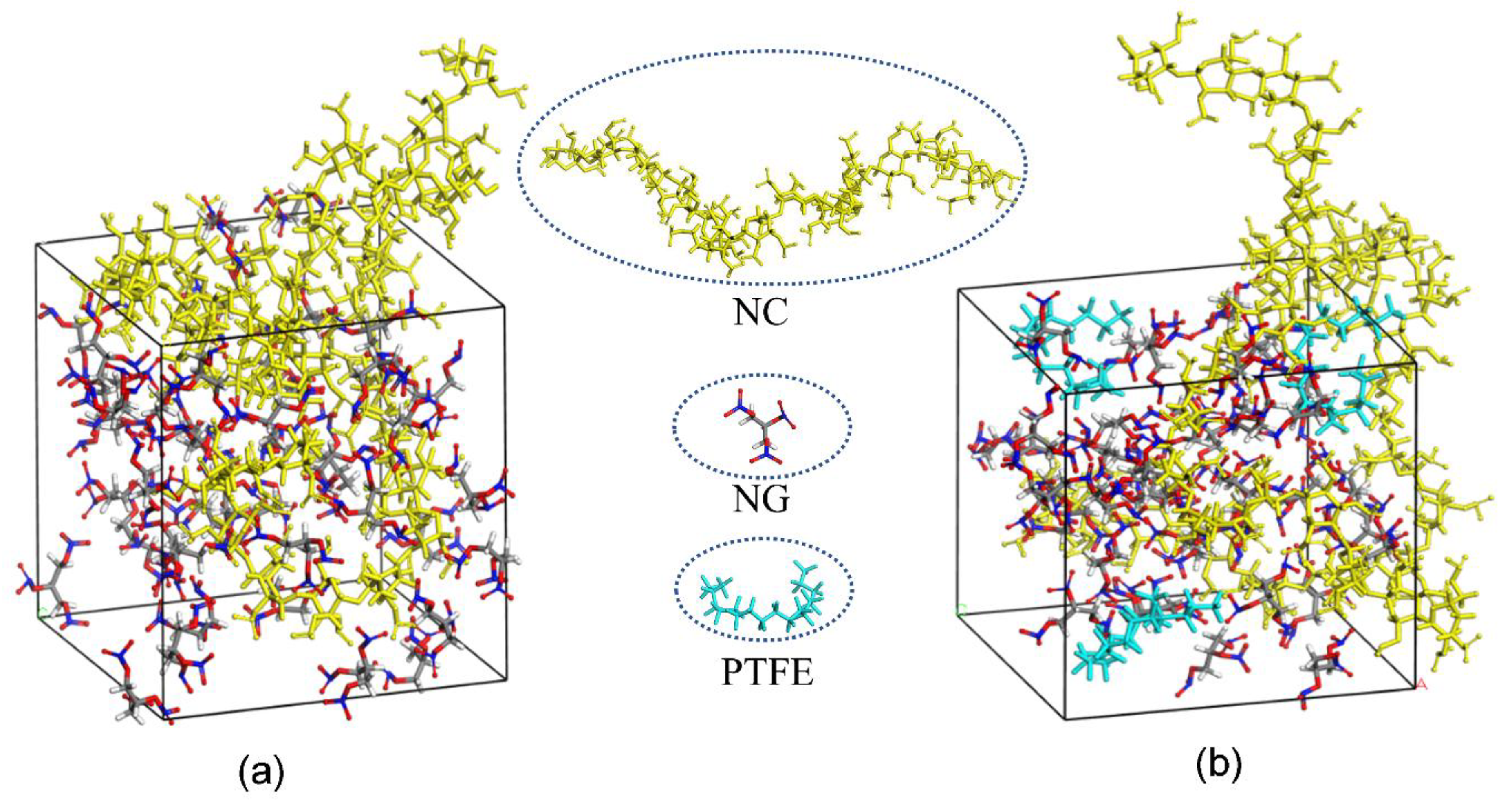
Based on the MD simulation results, modeling for the amorphous cells of NC/NG and PTFE/NC/NG are shown in
Figure 7. The diffusion coefficient (D) of NG can be obtained through linear regressions on the MSD vs. t curve (one-sixth the slope of the fitted regression line) [
39]. The detailed results are shown in
Table 6.
It can be found that the D of NG in DB propellant is a little faster than that in PTFE-DB propellant from
Table 6. It indicates that the NG motion could be suppressed by PTFE in DB propellant. This may be mainly caused by the interaction between NC/NG and PTFE molecules. Since the polarity of PTFE is almost completely counteracted due to the symmetrical structure, this interaction may be mainly dispersion forces resulting from instantaneous dipoles. The simulated results infer that the interaction between PTFE and NC/NG molecules could result in an 9–21% reduction in D.
It is worth noting that the distribution of PTFE in experimental sample is different to that in simulated sample. The fundamental purpose of simulation in this paper is to study the effect of PTFE molecules on the heat diffusion of NG. Thereby, we put PTFE in the built cell in molecule scale. While in experimental sample, there are many interfaces between nano PTFE fibers and NC/NG components. From this point of view, the reduction in D may be decreased to a large extent. However, the reduction of D from TGA data was not decreased obvious as shown in
Table 4 and
Table 5. Thereby, there may be some other factors limiting the migration of NG in experimental sample. Based on the fact that PTFE at the inner of the fibers cannot influence the NG molecules directly, we believe that the crystal PTFE fibers could act as inhibitions in a sense which has been proved could obvious limit NG diffusion in propellant. In summary, PTFE fibers could not only obvious improve propellant mechanical properties but also reduce the loss of NG during aging in a facile way. It is of practical importance for prolonging the service life of DB propellant and potentially expanding its application field.


