Article

Thermal and Mechanical Properties of Expanded Graphite/Paraffin Gypsum-Based Composite Material Reinforced by Carbon Fiber

1
Guangdong Provincial Laboratory of Durability for Marine Civil Engineering, Shenzhen University, Shenzhen 518060, China
2
Department of Architectural and Civil Engineering, City University of Hong Kong, Hong Kong 518000, China
*
Author to whom correspondence should be addressed.
Materials 2018, 11(11), 2205; https://doi.org/10.3390/ma11112205
Submission received: 5 October 2018 / Revised: 1 November 2018 / Accepted: 4 November 2018 / Published: 7 November 2018
(This article belongs to the Section Energy Materials)

Abstract

:
Phase change material (PCM) is a kind of thermal energy storage material. Solid-liquid PCM composite materials must overcome the issues of material leakage and low thermal conductivity before they are suitable for widespread use in the fields of building and industry. In this study, porous expanded graphite (EG) is used as a carrier, which absorbs the PCM to fabricate EG/paraffin composites (EG/P) containing 90.6% paraffin, and a latent heat of up to 105.3 J/g was measured. Because gypsum board is widely used in buildings, therefore, EG/P composites are suitable to be integrated into gypsum to develop expanded graphite/paraffin gypsum-based composite material (EGPG) for thermal energy storage. In order to optimize the performance of EGPG, carbon fiber (CF) is used to reinforce their thermal and mechanical properties. The test results show that when 1 wt % CF is incorporated into the EGPG, the thermal conductivity increased 36.0%, and thus EGPG shows superior thermal control through the significantly increased efficiency of heat transfer. After 1 wt % CF was added, the flexural and compressive strength of EGPG were increased by 65.6% and 6.4%, respectively. The improved thermal and mechanical performance of EGPG modified by CF demonstrates that it is a structural-functional integrated building material suitable for building envelope system.

1. Introduction

Energy consumption in the construction industry accounts for 40% of the total energy consumption and 30% of the annual greenhouse gas emissions [1]. Global energy reserves are becoming increasingly overwhelmed, thus energy-saving and environmentally friendly materials must be used to reduce the consumption of energy. This has motivated research into the development of thermal energy storage solutions, including sensible heat storage, latent heat storage, and electrochemical energy storage [2,3,4]. Latent heat storage is widely used in various fields, such as solar thermal energy storage and industrial waste heat recovery, due to its high energy storage density and isothermal phase transition temperature [5,6]. Additionally, the use of air-conditioners has increased as the thermal comfort index increases to meet the demand of higher living standards. Therefore, the use of latent heat storage materials, such as phase change materials (PCMs), combined with air conditioning systems in buildings may be used to significantly reduce energy consumption.
PCMs include both organic and inorganic PCMs. So far, inorganic PCMs are restricted in practical applications due to supercooling and phase segregation [7]. Organic PCMs are chemically inert and have good stability and corrosion resistance [8,9]. Paraffin, a typical organic phase change material, has been widely used because of its many advantages, including non-toxicity, stable chemical properties, no phase separation, low volume change during the phase change process, high enthalpy, and low cost [10]. However, the low thermal conductivity (about 0.24 W/m·K) of paraffin limits its widespread application because of inefficient heat transfer when absorbing or releasing thermal energy. In order to improve the thermal performance of paraffin as a PCM, its low conductivity should be modified.
Carbon-based materials are widely used for their high thermal conductivity or excellent mechanical properties. To improve the thermal management of insulated gate bipolar transistors (IGBT), Chang et al. [11] investigated the effects of nano-graphite sheet loading on paraffin to the thermal conductivity and shape-stability. They reported that the thermal conductivity of paraffin mixed with 15 wt % nano-graphite sheets was improved by five times compared to that of pure paraffin, and paraffin/nano-graphite sheets demonstrated greater shape stabilized properties. In addition, expanded graphite (EG) has been recognized for its low density, high porosity, high thermal conductivity, low price, and compatibility with organic phase change materials [12,13]. Hence, incorporating EG into paraffin could significantly increase its thermal conductivity and improve thermal transfer efficiency. Also, porous EG could be used as a carrier to absorb PCM to form a stabilized-shape phase change material (SSPCM), which could then prevent leakage of the paraffin during the process of melting. According to the research of Yang et al. [14], EG could absorb about 93.1% paraffin and the latent heat of the EG/paraffin was up to 152.8 J/g, which has potential for thermal energy storage applications. However, a cement paste containing 10 wt % EG/paraffin was found to have a compressive strength of 14.6 MPa, a reduction in compressive strength of 77.9% compared with pure cement paste. In practice, structural-functional integrated building materials are not only required to meet energy storage performance, but also must have a higher mechanical performance.
Carbon fiber has been used to reinforce composite materials due to its high tensile strength and thermal conductivity [15,16]. For example, Han et al. [17] proposed that after mixing 0.8 wt % CF into cement, the flexural strength is increased by 14.6% relative to a control sample without fiber. They explained that CF with high tensile strength could restrain the growth of cracks and it bonds well with hydration products, and thus it could enhance the flexural strength of cement by absorbing energy. However, they also mentioned that the addition of carbon fiber would cause a decrease of compressive strength due to the generation of a larger air void inside the matrix. Similar to Han et al. [17], Cui et al. [18] also found that CF helped to retrain crack pulling and thus improved the mechanical strength of cement. They presented, in that study, that the flexural strength of cement paste and alkali-activated slag mixed with 1 wt % CF was increased by 130.8% and 302.6%, respectively, after 28 days, compared with a control. The above research both illustrate that CF can be used to solve the matter of thermal energy storage building materials with low strengths. Apart from the reinforcement of mechanical strengths, Jiang et al. [19] used carbon fiber to prepare carbon bonded carbon fiber monoliths/PCM, and found that the in-plane thermal conductivity of the PCM composites was improved by 57 times over pure PCM, while the out-of-plane thermal conductivity was increased by 5.5 times. In addition, they showed that there was a linear relationship between the volume fractions of CF in the PCM composite with the improvement of thermal conductivity. Further improvement of thermal conductivity could achieve a higher heat transfer efficiency of PCM. In a word, CF is a promising candidate for enhancing the thermal and mechanical properties of structural-functional integrated building material.
Gypsum board usually was used as interior walls and ceiling board, while it does not have an energy storage function. If PCM was successfully integrated with the gypsum matrix, a structural-functional integrated gypsum board might be obtained and its application in building can be very wide-ranging [20,21]. Therefore, in this study, EG is used as a carrier to contain paraffin to fabricate EG/P with the aim of minimizing leakage and improving the thermal conductivity of paraffin. Besides, the morphology, thermal performance, and chemical structure of EG/P are characterized by scanning electron microscopy (SEM), differential scanning calorimeter (DSC), thermogravimetric analysis (TGA), and Fourier transform infrared (FT-IR) spectroscopy accordingly before it is incorporated into the gypsum matrix. Finally, the thermo-regulated performance and mechanical strengths of EGPG with or without CF was tested by means of a self-designed room model testing system.

2. Experimental

2.1. Materials

The paraffin used in the experiment, shown in Figure 1a, was purchased from Sinopec Group and has a latent heat of approximately 116.2 J/g. The melting and freezing temperatures are 20.8 °C and 19.4 °C, respectively, which is within the human comfort level (16–26 °C) [22]. The expanded graphite (EG), shown in Figure 1b, was supplied by Teng-sheng-da Carbon Machinery Co., Ltd. (Qingdao, China), and has an expansion ratio of 300. Polyacrylonitrile-based short carbon fibers (PAN-CF, 700SC-12K), shown in Figure 1c, with an average diameter of 7 μm and length of 3 mm, were purchased from Guangzhou Kaben Composite Materials Co., Ltd. (Guangzhou, China). The gypsum powder, shown in Figure 1d, was super hard gypsum with an initial setting time of 8–10 min and was purchased from Guangzhou Bosheng Gypsum Products Co., Ltd. (Guangzhou, China).

2.2. The Preparation and Characterization of EG/P

In this experiment, EG is used as a carrier for the paraffin. Firstly, the vacuum impregnation method [23] was used to press liquid paraffin into the mesopores of EG, then the mixture of EG/paraffin (EG/P) composite and liquid paraffin was filtered to remove excess paraffin. After filtering the solution, EG/P was drained on high adsorptive paper, and the paper placed in the oven at 60 °C. The paper was replaced frequently until the excess paraffin was removed and EG/P became a constant mass. Then, the EG/P (as shown in Figure 2a) could be collected.
To investigate fully the performance of the EG/P, many tests were conducted. DSC (Differential Scanning Calorimeter, DSC-200F3, Selb, Germany) was used to measure the melting and freezing temperature and enthalpy of the paraffin and EG/P. The temperature range of the measurement process was 0 °C to 60 °C, with a heating/cooling rate of 1 °C/min. A continuous nitrogen flow passes though the measurement system at a rate of 50 mL/min. The thermal stability of EG/P was determined by TGA (Thermal Analysis System, TGA Q50, New Castle, DE, USA). The sample was tested in a nitrogen atmosphere in a temperature range of 0–600 °C, using a heating rate of 10 °C/min. The chemical structure of paraffin and EG/P was detected by FT-IR (Fourier Transform Infrared Spectrometer, Perkin Elmer Spectrum 100, Toronto, ON, Canada), and the test wavelength ranged from 500 to 4000 cm−1. The microstructure of EG and EG/P was observed by FESEM (Field emission scanning electron microscope, SU-70, Tokyo, Japan) in the secondary electron mode.

2.3. The Preparation and Characterization of EGPG

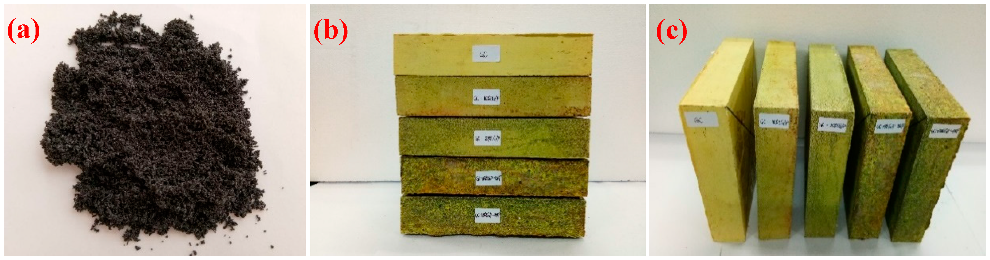
2.3.1. The Sample Preparation of EGPG

The mix proportion of EGPG is shown in Table 1. The procedures of sample preparation are as follows: Firstly, gypsum powder and EG/P were mixed and stirred for two minutes to ensure even dispersion of EG/P before water and CF were added into the stirring pot. The mixture was then stirred for 3 min at low-speed and a further 1 min at high-speed. After mixing, the EGPG was poured into one of three steel molds measuring either 40 mm × 40 mm × 160 mm to test the mechanical strength, 40 mm × 200 mm × 200 mm to test the thermos-regulated performance (shown in Figure 2b,c), or Φ30 mm × 40 mm to test the thermal conductivity. After 1 h, the samples were removed from the mold and then were kept indoors in a temperature and humidity-controlled environment (20 ± 1 °C and 60% RH) for 7 days before testing.

2.3.2. Thermal Conductivity Test

Thermal conductivity is one of the most important parameters for any PCM because it determines the heat transfer efficiency of the PCM. The thermal conductivity of EGPG were investigated using a thermal conductivity tester (XIATECH, TC3000, Xian, China) based on the hot wire method [24]. Each reported value was the average of three samples, and the maximum standard deviation measured was less than 0.002 W/(m·K). The measurement temperature ranged from 19 °C to 21 °C.

2.3.3. Thermo-Regulated Performance Test

The thermal-regulated performance of EGPG was measured through a self-designed room model [25], as shown in Figure 3a. A foam environmental chamber, as shown in Figure 3b, with internal dimensions of 1000 mm × 1000 mm × 1000 mm, was made to create a uniform temperature environment surrounding the small test room during heating and cooling. A small test room 290 mm × 290 mm × 285 mm in size was built. The test panel of EGPG with a size of 40 mm × 200 mm × 200 mm was placed on the top, acting as a ceiling panel. All sidewalls were made of polystyrene foam sheeting with a thickness of 45 mm. The internal dimension of the room was 200 mm × 200 mm × 200 mm, as shown in Figure 3c. The internal room temperature was recorded in real-time using a data-logger and thermocouples (Type K, ±0.3 °C), which were placed in the center of the small test room.
In this experiment, a fan heater was used for heating, while cooling was controlled by the air conditioning system programmed to maintain an ambient temperature at 17 °C. The top EGPG panel was heated for a period of 2.5 h and was then cooled down for another 3.5 h.

2.3.4. Temperature Cycling Test

To test the leakage behavior of EG/P, the thermal cycling chamber was used to accelerate the process of phase change. EG/P was enveloped between two filter paper sheets and compressed by 1 kPa static load as mentioned by Aydın et al. [26], and the samples then suffered different thermal cycles from 0 °C to 40 °C with 2 °C/min heating/cooling rate.
In addition, to know the change of mechanical strength after thermal cycling, the flexural and compressive strength of EGPG was evaluated again. After 7 days curing time in an indoor environment, the samples with a size of 40 mm × 40 mm × 160 mm were placed in the thermal cycling chamber for 500 thermal cycles from 10 °C to 40 °C with a 2 °C/min heating/cooling rate.

2.3.5. Strength Tests

After 7 days curing time and 500 thermal cycles (from 10 °C to 40 °C), the 40 mm × 40 mm × 160 mm samples were tested according to the requirements of the China national standard of GB/T 176167.3-1999 (test methods of strength of gypsum). Mechanical loading rates for flexural strength and compressive strength tests were 50 ± 10 N/s and 2.4 ± 0.2 KN/s, respectively.

2.3.6. Chemical Structure Tests

X-ray diffraction (XRD, Bruker D8 Advance, Karlsruhe, Germany) was using an angle range from 5° to 80° was used to measure any change in the material phase of the gypsum after thermal cycling.

3. Results and Discussion

3.1 Characterization of EG/P

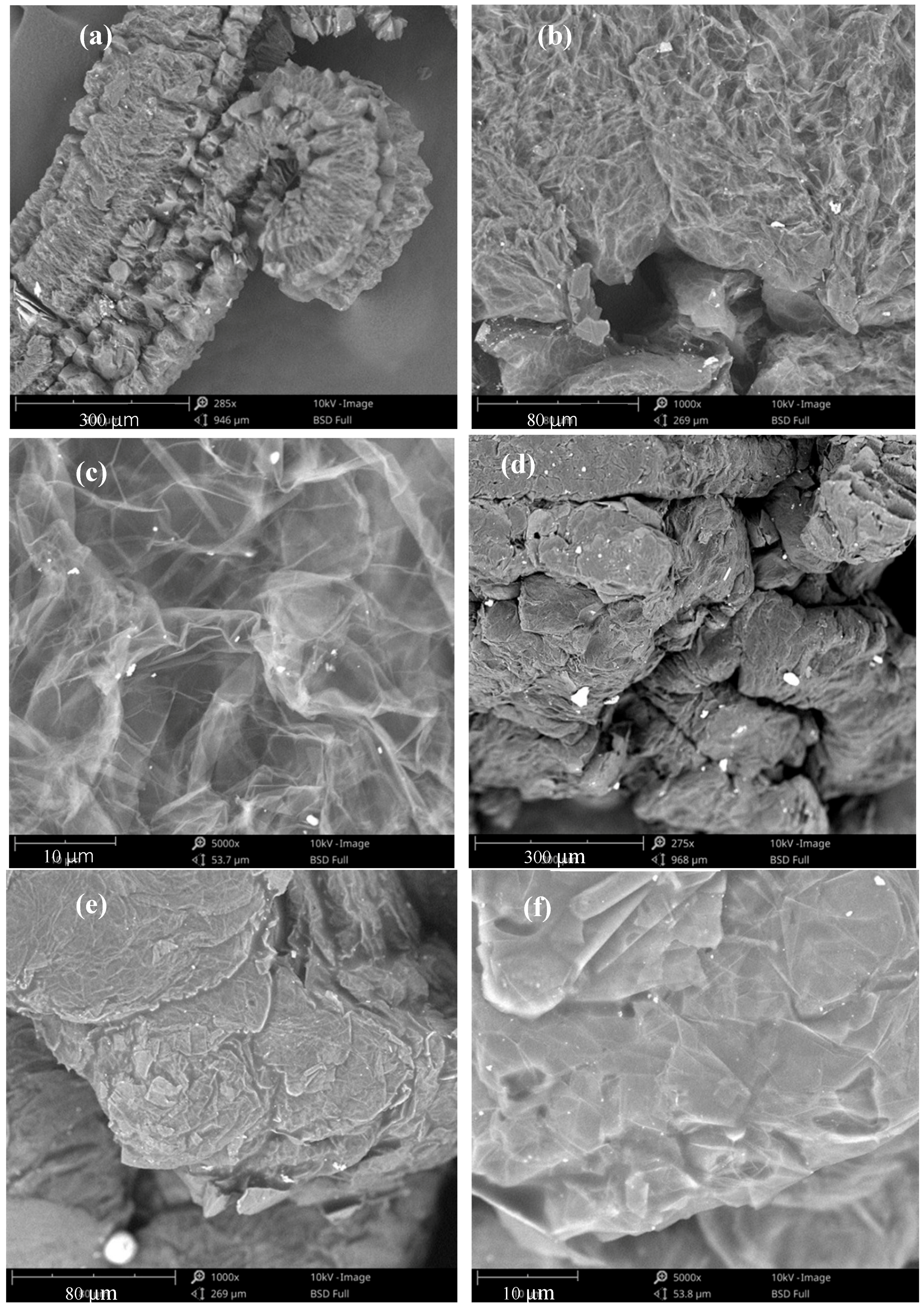
3.1.1. The Microstructure of EG and EG/P

Figure 4 shows the SEM images of EG and EG/P at different magnifications. The pores observed in the EG can be classified into one of three categories: (1) Interconnected and worm-like macrospores; (2) fractured pores on the surface; and (3) internal mesopores. Figure 4a shows a worm-like shape of EG and the pores on the surface are seen to be loose under a magnification of 285×. At a magnification of 1000 times, a large number of pores can be seen on the surface, as in Figure 4b. The network of mesopores in the EG are made by transparent and lamellar graphite, and can be observed at 5000 times magnification, as shown in Figure 4c. These large volume mesopores are able to absorb a large quantity of paraffin, which does not leak when in the liquid phase because of capillary action and surface tension [9,27].
Figure 4d shows the microstructure of EG/P magnified 280 times. From Figure 4d, it can be seen that the surface of EG is more compacted and the EG is stuck together after it absorbs paraffin. This may be due to residual paraffin on the surface of the EG, which acts as a binder to stick adjacent EG pieces together. Higher resolution images of EG are shown in Figure 4e,f, with a magnification of 1000× and 5000×. Compared with Figure 4b,c, the larger scale mesopores disappear and the denser microstructure is observed, indicating that the interior pores play a primary role on the absorption capacity. These results were consistent with Ren et al. [28], who presented that the mesopore sizes of EG is typically in the range of 3–5 nm, which could generate high capillary force and tension force. Thus, the PCM tends to adhere to the internal mesopore of EG. Additionally, they also demonstrated that there was little change on the enthalpy of EG/Ca(NO3)2-NaNO3 after 500 thermal cycles, indicating it has good thermal reliability for a long term period. It can be deducted that the leakage of paraffin from the interior of EG would not occur.

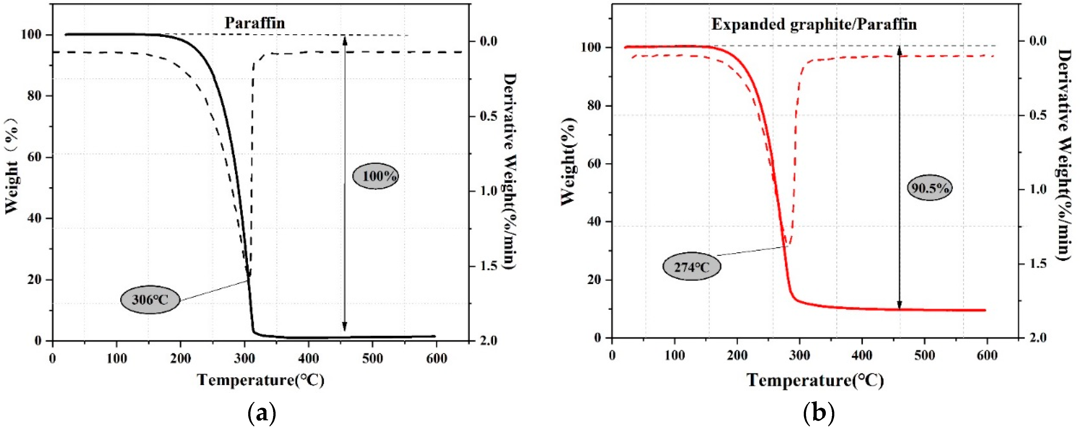
3.1.2. The Thermal Properties of EG/P

The thermo-physical properties of paraffin and EG/P were determined by DSC. As can be seen from Figure 5, the onset melting temperature of paraffin and EG/P are 20.8 °C and 22.3 °C, while its latent heat values are 110.7 J/g and 105.0 J/g, respectively. It can also see that the EG/P had a relatively higher onset melting temperature than that of pure paraffin. That may be explained by the Clapeyron-Clausius equation [29]:
ln T 2 T 1 = Δ α β V m Δ α β H m ( P 2 P 1 )
where, T1 and T2 represent the phase change temperature; Δ α β V m and Δ α β H m are the volume change and enthalpy change during the phase change from α-phase (solid state) to β-phase (liquid state); and P1 and P2 are the ambient pressures during the phase change. When the paraffin is melted, the enthalpy ( Δ s l H m ) and volume ( Δ s l V m ) of the paraffin would increase and pressure (P2 > P1) also increases [30], thus leading to an increase of the melting temperature.
With respect to the cooling process, it can be found from Figure 5 that the enthalpy of paraffin and EG/P are 121.6 J/g and 105.5 J/g, respectively. Meanwhile, the onset freezing temperature of EG/P shifted upward to 19.9 °C compared with that of pure paraffin by 19.4 °C. This result can be explained by the crystallization-promoting effect that the network of inner EG performed as a heterogeneous nucleation center to promote the crystallization reaction of paraffin during the crystallization process, resulting in the increase of onset crystallization [31].
In addition, according to the calculation method of Bao et al. [32], the encapsulation efficiency of EG was measured to be 90.6% by comparing the enthalpy of paraffin (116.2 J/g) and EG/P (105.3 J/g). In comparison to the works of Ramakrishnan et al. and Wen et al. [33,34], a higher value of latent heat of EG/P was obtained from this research. In research conducted by Ramakrishnan et al. [33], they prepared a form-stable phase change materials expanded perlite/paraffin and found that its enthalpy just had 80.1 J/g. Wen et al. [34] used diatomite as carrier and capric-lauric acid as PCM to fabricate the diatomite/capric-lauric acid. Although the enthalpy of capric-lauric acid was 141.5 J/g, diatomite/capric-lauric acid only owned 87.3 J/g. Therefore, it could be summarised that the high value of enthalpy achieved here demonstrates the potential of EG/P materials in building energy applications.
The thermal decomposition behavior of paraffin and EG/P were evaluated using TGA analysis. As shown in Figure 6, the weight-loss ratio of EG/P is approximately 90.5%, which is roughly equivalent to the mass ratio of paraffin calculated from DSC. This indirectly proves the homogeneity of the samples and the accuracy of the measurement techniques.
It can be seen that both paraffin and EG/P started to decompose at approximately 180 °C. That implies the thermal stability of paraffin is not changed despite being incorporated into EG, and the decomposition temperature was suitable for the engineering application. However, a significant difference between paraffin and EG/P can also be found in Figure 6. When the EG/P is heated to 274 °C, the paraffin inside the EG is completely decomposed, while pure paraffin must be heated to 306 °C. A similar result can be found by the research of Zhang et al. [31]. In their study, it can be found that polyethylene glycol started to decompose at 409 °C, while the decomposition temperature of EG/polyethylene glycol occurred at 391 °C. This phenomenon can be explained by the mechanism that EG could provide an enhancement in the thermal conductivity of the material, resulting in a faster response to applied heat and a higher heat transfer efficiency. Based on the above discussion, EP/G, which has a suitable phase change temperature, high enthalpy, and good thermal stability, can be used as an energy storage material for buildings.

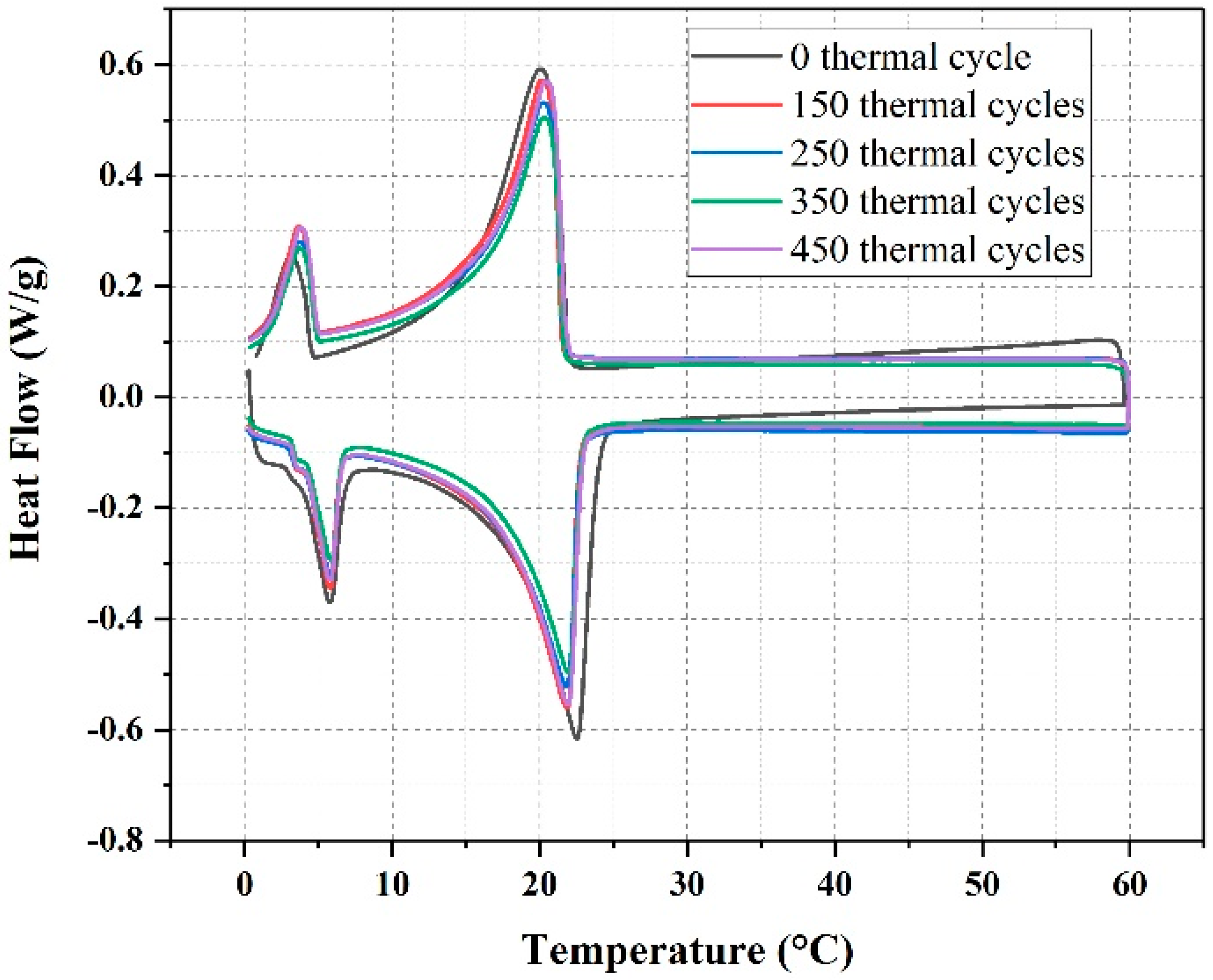
3.1.3. The Thermal Reliability of EG/P

The thermal reliability of EG/P was evaluated using DSC analysis by comparing before and after thermal cycles. As shown in Figure 7 and Table 2, the average enthalpy of EG/P with 150, 250, 350, and 450 thermal cycles are 105.1 J/g, 103.9 J/g, 103.2 J/g, and 103.0 J/g accordingly, which are roughly equivalent to that enthalpy without any thermal cycles. Although the enthalpy of EG/P has a few decreases under thermal cycles, these results can still confirm that the enthalpy of EG/P is guaranteed. Besides, from Table 2, it is clear that the onset melting temperature drops and onset freezing temperature rises after thermal cycles, but are not significant, indicating EG/P has stable melting and freezing points. Therefore, it can be concluded that the newly developed EG/P has excellent thermal reliability.

3.1.4. The Chemical Structure of EG/P

The FT-IR spectrum of paraffin, EG, and EG/P between 4000 cm−1 to 500 cm−1 are shown in Figure 8. The characteristic peak at 719 cm−1 that is observed for paraffin, EG, and EG/P is related to the rocking vibration of CH2 [35]. The peak observed at 1380 cm−1 for EG and EG/P samples is related to the symmetric deformation of CH3, and the absorption peak at 1473 cm−1 is caused by the asymmetric stretching vibration of the CH2 group [36]. A further two strong absorption peaks (2350 cm−1 and 2360 cm−1) are observed in the EG and EG/P samples, which is due to the stretching vibration of the C–C skeleton in EG [37]. Figure 8 also shows oscillating bands at 2849 cm−1 and 2918 cm−1 that are linked to the stretching vibrations of CH2 and CH3, respectively [36]. However, there are no new characteristic absorption bands in the EG/P sample, indicating that the absorption process of paraffin into EG is a physical interaction only with no chemical reaction.

3.2. Thermal Conductivity of EGPG

As shown in Table 3, it can be seen that the thermal conductivity of GC increases with an increasing concentration of EG/P. Compared with GC, when 10 wt % and 20 wt % of EG/P are added into GC, the thermal conductivity of GC-10%EG/P and GC-20%EG/P increases by 33.7% and 53.2%, respectively. This improvement was attributed to the high thermal conductivity of EG/P (about 5 W/m·K) [35], and it could improve the thermal conductivity of EGPG. In addition, incorporating CF into the GC also improved thermal conductivity. The thermal conductivity of GC-10%EG/P and GC-20%EG/P was increased by 36.0% and 28.6%, respectively, with the addition of 1 wt % of CF. It can also be expected that the thermal exchange rate of GC-10%EG/P and GC-20%EG/P will also improve significantly with the inclusion of CF because of the high thermal conductivity that is achieved.

3.3. The Thermo-Regulated Performance of EGPG

According to Equation (2), the energy storage capacity of EGPG can be calculated, and Table 3 shows the results for each gypsum board.
Δ H E G P G = Δ H E G / P ×   m E G / P m g y p s u m +   m w a t e r + m E G / P + m C F
where ΔHEGPG and ΔHEG/P represent the energy storage capacity of EGPG and EG/P, respectively; and mEG/P, mgypsum, mwater, and mCF present the weight of EG/P, gypsum, water, and CF accordingly.
The thermo-regulated performance of EGPG is evaluated through a self-designed room model. As seen in Figure 9, a similar trend of the temperature variation with time is observed for all EGPG groups. It also can observed that GC has a faster heating and cooling process compared with the other groups. This implies that the GC group had a poor energy storage capacity. However, the test panels containing EG/P show improved temperature regulation properties when compared to GC. That is due to the inclusion of EG/P, which has a high energy storage capacity and is able to absorb a significant amount of heat during the heating phase (0 to 150 min). The heat stored by the EG/P is then released to slow the rate of decreasing temperatures during the cooling phase. Moreover, the thermo-regulated performance of the EGPG was even more effective with an increase in EG/P content. For example, when the highest measured temperature of GC is reached at 26.7 °C (maximum temperature, 159 min), the temperature of GC-10%EG/P and GC-20%EG/P were measured to be 25.4 °C and 24.3 °C, respectively. This represents an improvement compared with the reference GC for a GC-10%EG/P and GC-20%EG/P of 1.3 °C and 2.4 °C, respectively. According to the research of Mourid et al. [38], a PCM coating of 5.3 mm thickness on a standard wall could lead to a temperature increase of about 6 °C during the night and reduce energy consumption by 20% compared to the reference case. In addition to reducing the energy consumption, our previous research [39] shows that a 4 mm thick PCM panel integrated into a wall could improve the energy efficiency rate by 65.3%, and it is equivalent to reducing CO2 greenhouse gases emissions by 65.28%. This indicates that EGPG materials are able to reduce temperature fluctuations, resulting in reduced electricity consumption of heating and cooling systems, which has the effect of improving the power generation management and reducing environmental pollution to achieve an improved economic outcome.
The effect of adding CF to EGPG can also be seen in Figure 9. GC-10%EG/P-1%CF and GC-20%EG/P-1%CF show an improved thermo-regulated performance than that of GC-10%EG/P and GC-20%EG/P. Based on the results of Section 3.2, it can be deduced that CF increases the thermal conductivity of GC-10%EG/P and GC-20%EG/P, and thus improves the heat transfer rate of EG/P within the EGPG matrix. Specifically, the maximum temperature of GC-10%EG/P-1%CF and GC-20%EG/P-1%CF decreased by 0.6 °C and 0.8 °C compared with GC-10%EG/P and GC-20%EG/P, respectively. Hence, it can be concluded that the matrix with the highest thermal conductivity provides the greatest increase in the heat transfer rate to the PCM, thus improving the thermo-regulated performance of structural-functional integrated building materials.

3.4. The Mechanical Properties of EGPG

The mechanical properties of EGPG were tested after seven days curing time under ambient conditions, and the results are shown in Figure 10. It was found that with an increasing EG/P content, a decreasing trend in the flexural and compressive strength was observed. For example, when 10 wt % and 20 wt % of EG/P were mixed with GC, the flexural strength of GC-10% EG/P and GC-20% EG/P was reduced by 36.0% and 50.0% compared with the reference GC material, respectively. The compressive strength of GC-10%EG/P and GC-20%EG/P was found to decrease by 61.2% and 72.8%. This result may be due to the fact that a higher total porosity can be generated due to the addition of EG/P, which leads to the observed reduction in mechanical strength [40]. In the research conducted by Pilehvar et al. [41], the compressive strength of cement had a large reduction from 60 MPa to 35 MPa at 28 days when 20% microencapsulted PCM was incorporated. They explained that this pheromone is because the lower stiffness and strength of EG/P could weaken the mechanical strength of GC. However, 1 wt % CF has been found to improve the mechanical strength of EGPG. The flexural strength of GC-10%EG/P-1%CF is 12.4 MPa, which is 51.6% higher than that of GC-10%EG/P, while no change in compressive strength was observed. These results were consistent with Zhu et al. [42], who reported that the fibers with high bond strength increase the brittleness of plaster gypsum-based materials. In their study, the flexural strength of gypsum increased by 91.5% from 2.1 MPa to 4.04 MPa as the addition of 1.2% polyvinyl alcohol fiber with the length of 12 mm.
A temperature cycling test was used to measure the change in mechanical strength of EGPG materials under service conditions. Figure 11 shows the results of the mechanical strength after 500 heating/cooling cycles from 10 to 40 °C. It is seen that the flexural and compressive strengths of EGPG are doubled after temperature cycling compared with samples after seven days curing at room temperature. Based on the results of SEM and XRD, dehydration of the gypsum is identified as the main cause of the higher mechanical strength. The morphology of gypsum before temperature cycling, as shown in Figure 12a, is calcium sulfate dihydrate (CaSO4·2H2O), which has rod and thick plate-like crystals measuring 6–15 μm. In comparison, irregular block crystals (calcium sulfate hemihydrate-CaSO4·0.5H2O, 2–10 μm) are observed after thermal cycling as shown in Figure 12b, which has a positive effect on improving the mechanical strength. Figure 13 shows that CF distributes in the cracks and on the surface of EGPG, which contributes to the higher mechanical strength. Besides, XRD results also have confirmed that CaSO4·2H2O transformed to CaSO4·0.5H2O after thermal cycling, as shown in Figure 14. As shown from the sample before thermal cycling (black curve), the characteristic peaks are mainly generated at 11.7°, 20.6°, 23.6°, 29.2°, 31.1°, and 33.4°, which belong to CaSO4·2H2O [43]. However, in the sample after thermal cycling (red curve), the characteristic peaks are identified at 14.9°, 25.8°, 29.7°, and 32.0°, corresponding to the peak of CaSO4·0.5H2O.

4. Conclusions

In this study, EG/P was developed for use in a gypsum-based thermal energy storage material for application as interior partitions or building envelope materials. Carbon fiber (CF) was used to improve the thermal conductivity and mechanical strength of the gypsum matrix to increase the rate of heat exchange of EG/P and allow its use in a wide range of building applications. The following conclusions can be drawn from the experimental findings:
  • EG/P was prepared successfully by the vacuum impregnation method, which produces material with a latent heat storage capacity of 105.3 J/g and phase change temperature of 22.28 °C. The results of FT-IR reveal that the components within EG/P are chemically compatible, and TGA proves that EG/P can meet the requirements for thermal stability. As a result, EG/P is demonstrated as a potential candidate for buildings as part of overall efficient energy management scheme.
  • Both EG/P and CF improved the thermal conductivity of gypsum (GC). Compared with GC, the thermal conductivity of the GC-10%EG/P and GC-20%EG/P was improved by 33.7% and 53.2%, respectively. When 1 wt % CF was added, the thermal conductivity of GC-10%EG/P and GC-20%EG/P further increases by 36.0% and 28.6%, respectively.
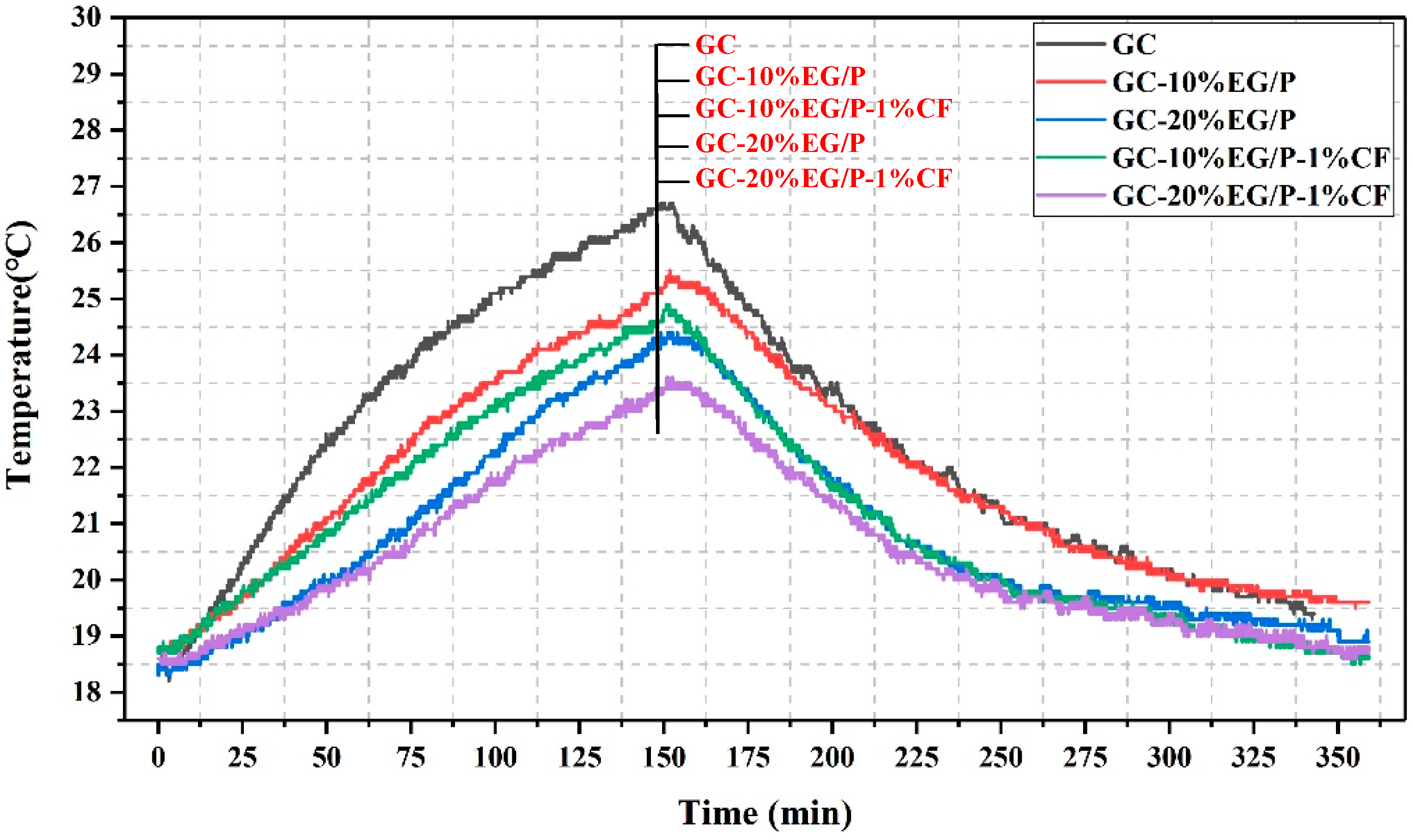
  • EG/P can significantly reduce temperature fluctuations. The maximum temperature of indoor center position decreased by 2.4 °C with the addition of 20 wt % EG/P into GC. CF also has a role in increasing the rate of heat transfer to EG/P within gypsum, and thus the greatest improvement in temperature was 3.2 °C, observed between GC-20%EG/P-1%CF and GC.
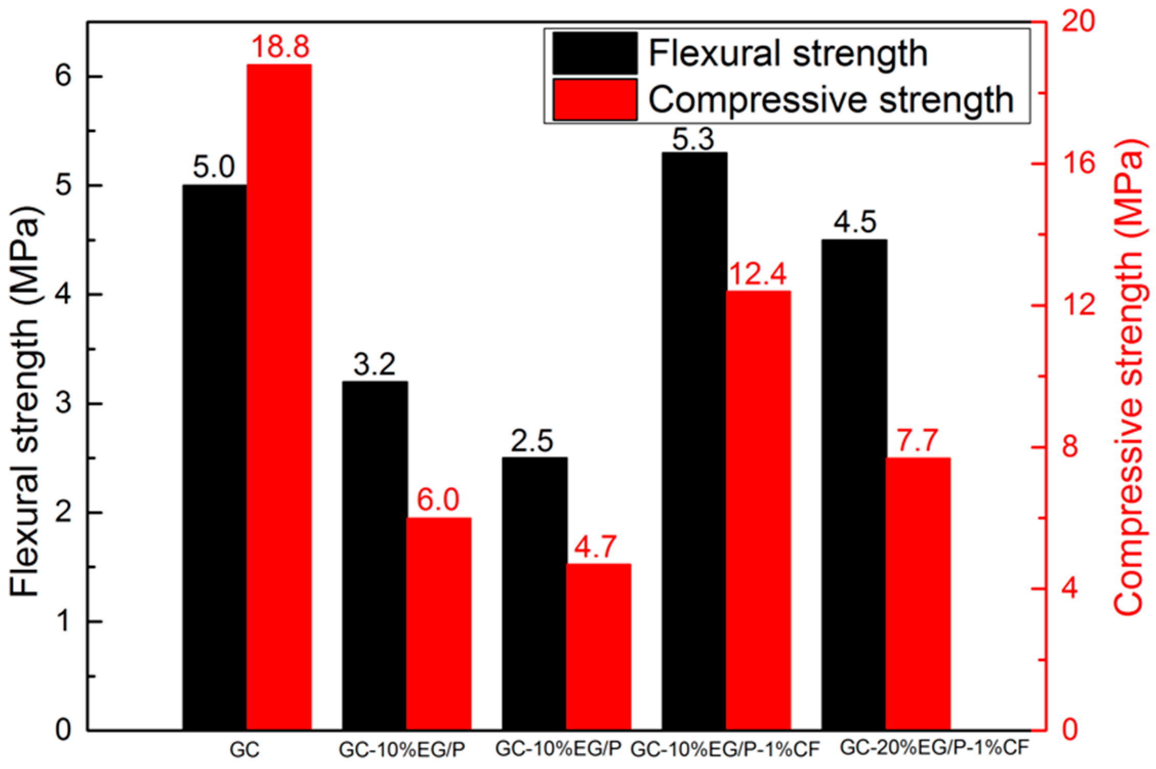
  • With the increase of EG/P content, the flexural and compressive strengths of EGPG demonstrate a dramatically decreasing trend. However, the presence of CF can improve the flexural strength of GC-20%EG/P by 51.6%, with no change in compressive strength.
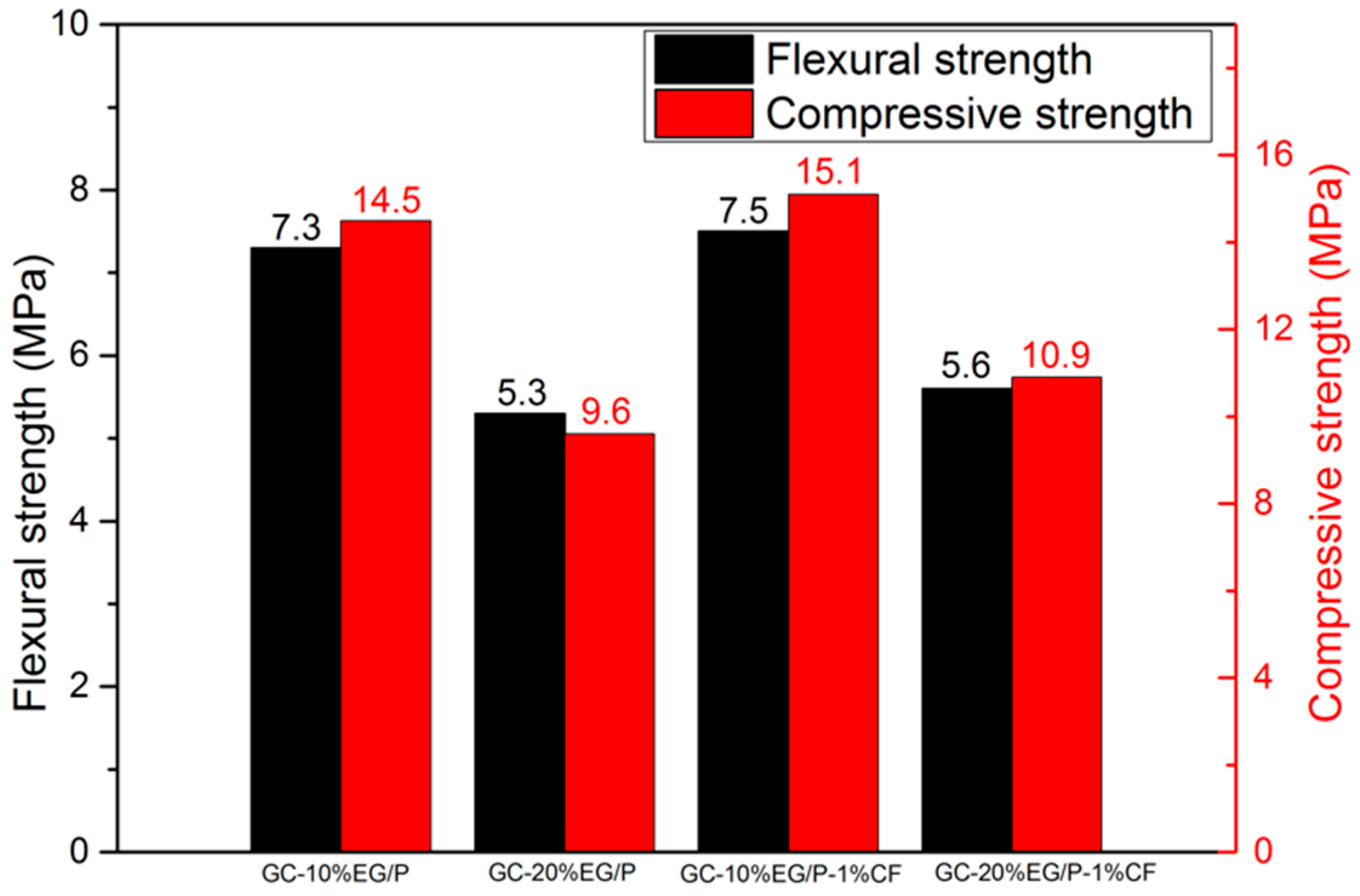
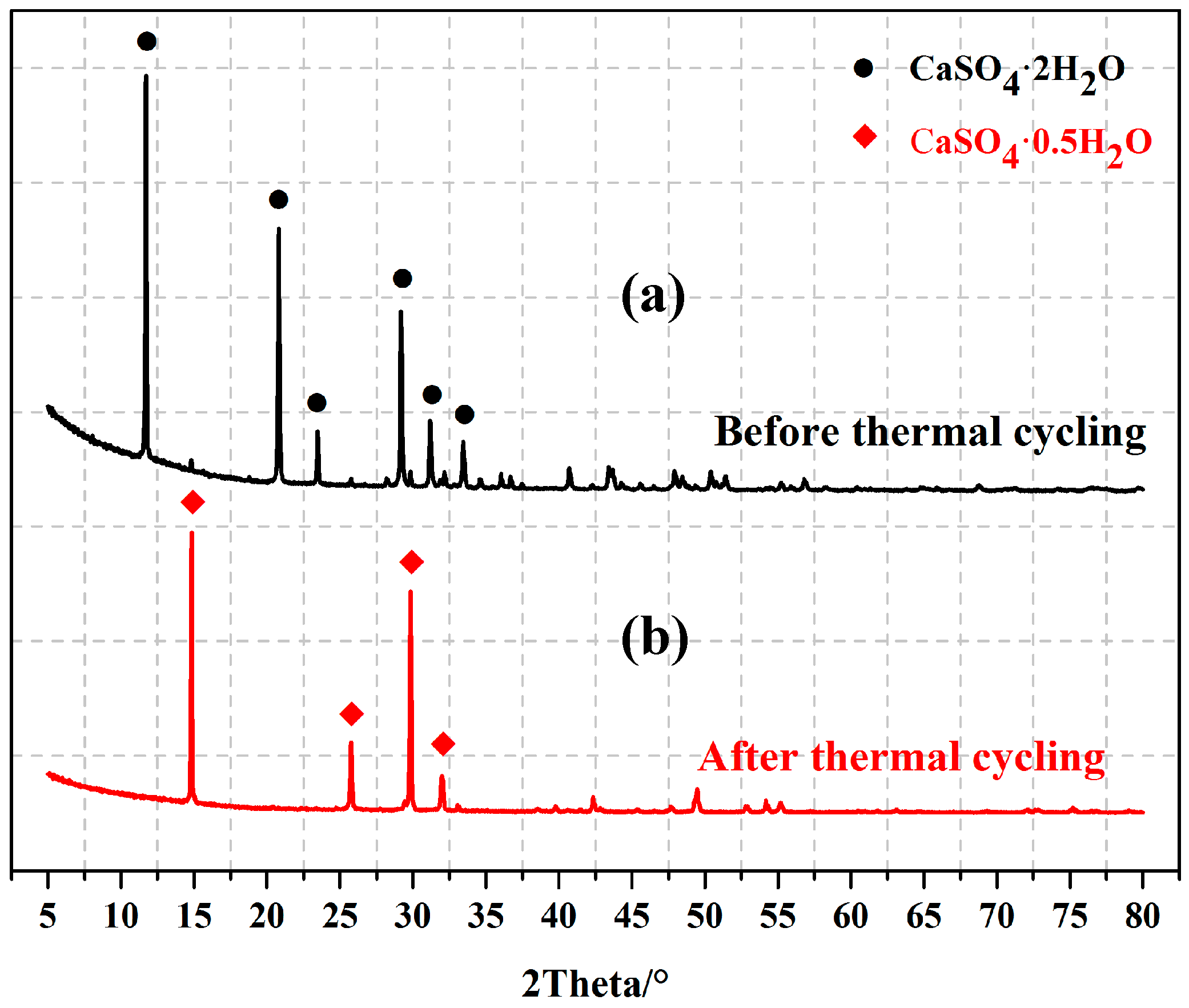
  • After 500 heating/cooling cycles, the mechanical properties of EGPG increased by about 100%, which is attributed to the dehydration of calcium sulfate dihydrate.

Author Contributions

B.Z. did the experiments and data analysis and wrote part of this paper. Y.T. did the experiments and data analysis and wrote part of this paper. X.J. did the data analysis. T.Y.L. wrote part of this paper. H.C. provided the original ideas and did the experiments and data analysis.

Funding

This research received no external funding.

Acknowledgments

The work described in this paper was fully supported by grants from Natural Science Foundation of China (51678367).

Conflicts of Interest

The authors declare no conflict of interest.

Abbreviations

PCMsPhase Change Materials
EGExpanded graphite
EG/PExpanded graphite/Paraffin composites
SSPCMStabilized-shape Phase Change Material
EGPGExpanded graphite/paraffin gypsum-based composite material
CFCarbon Fiber

References

  1. Rao, V.V.; Parameshwaran, R.; Ram, V.V. PCM-mortar based construction materials for energy efficient buildings: A review on research trends. Energy Build. 2018, 158, 95–122. [Google Scholar] [CrossRef]
  2. Stritih, U.; Tyagi, V.V.; Stropnik, R.; Paksoy, H.; Haghighat, F.; Joybari, M.M. Integration of passive PCM technologies for net-zero energy buildings. Sustain. Cities Soc. 2018, 41, 286–295. [Google Scholar] [CrossRef]
  3. Fernandes, D.; Pitié, F.; Cáceres, G.; Baeyens, J. Thermal energy storage: “How previous findings determine current research priorities”. Energy 2012, 39, 246–257. [Google Scholar] [CrossRef]
  4. Bhale, P.V.; Rathod, M.K.; Sahoo, L. Thermal Analysis of a Solar Concentrating System Integrated with Sensible and Latent Heat Storage. Energy Procedia 2015, 75, 2157–2162. [Google Scholar] [CrossRef]
  5. Memon, S.A.; Lo, T.Y.; Cui, H.; Barbhuiya, S. Preparation, characterization and thermal properties of dodecanol/cement as novel form-stable composite phase change material. Energy Build. 2013, 66, 697–705. [Google Scholar] [CrossRef]
  6. Şahan, N.; Paksoy, H. Novel shapeable phase change material (PCM) composites for thermal energy storage (TES) applications. Sol. Energy Mater. Sol. Cells 2018, 174, 380–387. [Google Scholar] [CrossRef]
  7. Xu, X.; Cui, H.; Memon, S.A.; Yang, H.; Tang, W. Development of novel composite PCM for thermal energy storage using CaCl2·6H2O with graphene oxide and SrCl2·6H2O. Energy Build. 2017, 156, 163–172. [Google Scholar] [CrossRef]
  8. Liu, L.; Su, D.; Tang, Y.; Fang, G. Thermal conductivity enhancement of phase change materials for thermal energy storage: A review. Renew. Sustain. Energy Rev. 2016, 62, 305–317. [Google Scholar] [CrossRef]
  9. Yang, Y.; Pang, Y.; Liu, Y.; Guo, H. Preparation and thermal properties of polyethylene glycol/expanded graphite as novel form-stable phase change material for indoor energy saving. Mater. Lett. 2018, 216, 220–223. [Google Scholar] [CrossRef]
  10. Li, L.; Wang, G.; Guo, C. Influence of intumescent flame retardant on thermal and flame retardancy of eutectic mixed paraffin/polypropylene form-stable phase change materials. Appl. Energy 2016, 162, 428–434. [Google Scholar] [CrossRef]
  11. Chang, T.-C.; Lee, S.; Fuh, Y.-K.; Peng, Y.-C.; Lin, Z.-Y. PCM based heat sinks of paraffin/nanoplatelet graphite composite for thermal management of IGBT. Appl. Therm. Eng. 2017, 112, 1129–1136. [Google Scholar] [CrossRef]
  12. Zhang, Z.; Fang, X. Study on paraffin/expanded graphite composite phase change thermal energy storage material. Energy Convers. Manag. 2006, 47, 303–310. [Google Scholar] [CrossRef]
  13. Karaipekli, A.; Biçer, A.; Sarı, A.; Tyagi, V.V. Thermal characteristics of expanded perlite/paraffin composite phase change material with enhanced thermal conductivity using carbon nanotubes. Energy Convers. Manag. 2017, 134, 373–381. [Google Scholar] [CrossRef]
  14. Yang, H.; Memon, S.; Bao, X.; Cui, H.; Li, D. Design and Preparation of Carbon Based Composite Phase Change Material for Energy Piles. Materials 2017, 10, 391. [Google Scholar] [CrossRef] [PubMed]
  15. Chuang, W.; Geng-Sheng, J.; Bing-Liang, L.; Lei, P.; Ying, F.; Ni, G.; Ke-Zhi, L. Dispersion of carbon fibers and conductivity of carbon fiber-reinforced cement-based composites. Ceram. Int. 2017, 43, 15122–15132. [Google Scholar] [CrossRef]
  16. Hou, L.G.; Wu, R.Z.; Wang, X.D.; Zhang, J.H.; Zhang, M.L.; Dong, A.P.; Sun, B.D. Microstructure, mechanical properties and thermal conductivity of the short carbon fiber reinforced magnesium matrix composites. J. Alloys Compd. 2017, 695, 2820–2826. [Google Scholar] [CrossRef]
  17. Han, B.; Zhang, L.; Zhang, C.; Wang, Y.; Yu, X.; Ou, J. Reinforcement effect and mechanism of carbon fibers to mechanical and electrically conductive properties of cement-based materials. Constr. Build. Mater. 2016, 125, 479–489. [Google Scholar] [CrossRef]
  18. Cui, H.; Feng, T.; Yang, H.; Bao, X.; Tang, W.; Fu, J. Experimental study of carbon fiber reinforced alkali-activated slag composites with micro-encapsulated PCM for energy storage. Constr. Build. Mater. 2018, 161, 442–451. [Google Scholar] [CrossRef]
  19. Jiang, Z.; Ouyang, T.; Yang, Y.; Chen, L.; Fan, X.; Chen, Y.; Li, W.; Fei, Y. Thermal conductivity enhancement of phase change materials with form-stable carbon bonded carbon fiber network. Mater. Des. 2018, 143, 177–184. [Google Scholar] [CrossRef]
  20. Oliver, A. Thermal characterization of gypsum boards with PCM included: Thermal energy storage in buildings through latent heat. Energy Build. 2012, 48, 1–7. [Google Scholar] [CrossRef]
  21. Karaipekli, A.; Sarı, A. Development and thermal performance of pumice/organic PCM/gypsum composite plasters for thermal energy storage in buildings. Sol. Energy Mater. Sol. Cells 2016, 149, 19–28. [Google Scholar] [CrossRef]
  22. Ali Memon, S.; Yiu Lo, T.; Shi, X.; Barbhuiya, S.; Cui, H. Preparation, characterization and thermal properties of Lauryl alcohol/Kaolin as novel form-stable composite phase change material for thermal energy storage in buildings. Appl. Therm. Eng. 2013, 59, 336–347. [Google Scholar] [CrossRef]
  23. Zhang, X.; Wen, R.; Huang, Z.; Tang, C.; Huang, Y.; Liu, Y.; Fang, M.; Wu, X.; Min, X.; Xu, Y. Enhancement of thermal conductivity by the introduction of carbon nanotubes as a filler in paraffin/expanded perlite form-stable phase-change materials. Energy Build. 2017, 149, 463–470. [Google Scholar] [CrossRef]
  24. Rao, Z.; Zhang, G.; Xu, T.; Hong, K. Experimental study on a novel form-stable phase change materials based on diatomite for solar energy storage. Sol. Energy Mater. Sol. Cells 2018, 182, 52–60. [Google Scholar] [CrossRef]
  25. Cui, H.; Tang, W.; Qin, Q.; Xing, F.; Liao, W.; Wen, H. Development of structural-functional integrated energy storage concrete with innovative macro-encapsulated PCM by hollow steel ball. Appl. Energy 2017, 185, 107–118. [Google Scholar] [CrossRef]
  26. Aydın, A.A.; Okutan, H. Polyurethane rigid foam composites incorporated with fatty acid ester-based phase change material. Energy Convers. Manag. 2013, 68, 74–81. [Google Scholar] [CrossRef]
  27. Yuan, Y.; Yuan, Y.; Zhang, N.; Du, Y.; Cao, X. Preparation and thermal characterization of capric–myristic–palmitic acid/expanded graphite composite as phase change material for energy storage. Mater. Lett. 2014, 125, 154–157. [Google Scholar] [CrossRef]
  28. Ren, Y.; Xu, C.; Yuan, M.; Ye, F.; Ju, X.; Du, X. Ca(NO3)2-NaNO3/expanded graphite composite as a novel shape-stable phase change material for mid- to high-temperature thermal energy storage. Energy Convers. Manag. 2018, 163, 50–58. [Google Scholar] [CrossRef]
  29. Xia, L.; Zhang, P.; Wang, R.Z. Preparation and thermal characterization of expanded graphite/paraffin composite phase change material. Carbon 2010, 48, 2538–2548. [Google Scholar] [CrossRef]
  30. Zhang, D.; Zhou, J.; Wu, K.; Li, Z. Granular phase changing composites for thermal energy storage. Sol. Energy 2005, 78, 471–480. [Google Scholar] [CrossRef]
  31. Zhang, D.; Chen, M.; Wu, S.; Liu, Q.; Wan, J. Preparation of expanded graphite/polyethylene glycol composite phase change material for thermoregulation of asphalt binder. Constr. Build. Mater. 2018, 169, 513–521. [Google Scholar] [CrossRef]
  32. Bao, X.; Memon, S.; Yang, H.; Dong, Z.; Cui, H. Thermal Properties of Cement-Based Composites for Geothermal Energy Applications. Materials 2017, 10, 462. [Google Scholar] [CrossRef] [PubMed]
  33. Ramakrishnan, S.; Wang, X.; Sanjayan, J.; Wilson, J. Assessing the feasibility of integrating form-stable phase change material composites with cementitious composites and prevention of PCM leakage. Mater. Lett. 2017, 192, 88–91. [Google Scholar] [CrossRef]
  34. Wen, R.; Zhang, X.; Huang, Z.; Fang, M.; Liu, Y.; Wu, X.; Min, X.; Gao, W.; Huang, S. Preparation and thermal properties of fatty acid/diatomite form-stable composite phase change material for thermal energy storage. Sol. Energy Mater. Sol. Cells 2018, 178, 273–279. [Google Scholar] [CrossRef]
  35. Xu, T.; Li, Y.; Chen, J.; Wu, H.; Zhou, X.; Zhang, Z. Improving thermal management of electronic apparatus with paraffin (PA)/expanded graphite (EG)/graphene (GN) composite material. Appl. Therm. Eng. 2018, 140, 13–22. [Google Scholar] [CrossRef]
  36. Xu, B.; Li, Z. Paraffin/diatomite/multi-wall carbon nanotubes composite phase change material tailor-made for thermal energy storage cement-based composites. Energy 2014, 72, 371–380. [Google Scholar] [CrossRef]
  37. Han, X.; Zhao, T.; Gao, X.; Li, H. Preparation and characterization of high-temperature non-flowing SiO2/EG/paraffin composites by high-temperature refining. Colloids Surf. A Physicochem. Eng. Asp. 2018, 542, 1–7. [Google Scholar] [CrossRef]
  38. Mourid, A.; El Alami, M.; Kuznik, F. Experimental investigation on thermal behavior and reduction of energy consumption in a real scale building by using phase change materials on its envelope. Sustain. Cities Soc. 2018, 41, 35–43. [Google Scholar] [CrossRef]
  39. Cui, H.; Memon, S.A.; Liu, R. Development, mechanical properties and numerical simulation of macro encapsulated thermal energy storage concrete. Energy Build. 2015, 96, 162–174. [Google Scholar] [CrossRef]
  40. Liu, Y.; Xie, M.; Gao, X.; Yang, Y.; Sang, Y. Experimental exploration of incorporating form-stable hydrate salt phase change materials into cement mortar for thermal energy storage. Appl. Therm. Eng. 2018, 140, 112–119. [Google Scholar] [CrossRef]
  41. Pilehvar, S.; Cao, V.D.; Szczotok, A.M.; Valentini, L.; Salvioni, D.; Magistri, M.; Pamies, R.; Kjøniksen, A.-L. Mechanical properties and microscale changes of geopolymer concrete and Portland cement concrete containing micro-encapsulated phase change materials. Cem. Concr. Res. 2017, 100, 341–349. [Google Scholar] [CrossRef]
  42. Zhu, C.; Zhang, J.; Peng, J.; Cao, W.; Liu, J. Physical and mechanical properties of gypsum-based composites reinforced with PVA and PP fibers. Constr. Build. Mater. 2018, 163, 695–705. [Google Scholar] [CrossRef]
  43. Tan, H.; Dong, F.; Liu, J. Morphology control of calcium sulfate hemihydrates and application in size screening iron/sulfur of jarosite sediment. J. Phys. Chem. Solids 2018, 112, 239–245. [Google Scholar] [CrossRef]
Figure 1. The morphology of the raw materials: (a) Paraffin; (b) EG (Expanded Graphite); (c) carbon fiber; (d) gypsum.
Materials 11 02205 g001
Figure 2. The morphology of the prepared materials: (a) Appearance of the prepared EG/P; (b,c) prepared gypsum board.
Materials 11 02205 g002
Figure 3. Schematic diagrams of thermal performance testing: (a) Testing system; (b) section of the testing system; (c) small house model.
Materials 11 02205 g003
Figure 4. SEM images of EG and EG/P: (a) 285× magnification of EG; (b) 1000× magnification of EG; (c) 5000× magnification of EG; (d) 280× magnification of EG/P; (e) 1000× magnification of EG/P; (f) 5000× magnification of EG/P.
Materials 11 02205 g004
Figure 5. DSC (Differential Scanning Calorimeter) curves of paraffin and expanded graphite/paraffin.
Materials 11 02205 g005
Figure 6. TGA (Thermal Analysis System) and DTG (Derivative Thermogravimetric Analysis) curves of (a) paraffin and (b) expanded graphite/paraffin.
Materials 11 02205 g006
Figure 7. DSC curves of expanded graphite/paraffin under different thermal cycles.
Materials 11 02205 g007
Figure 8. FT-IR spectrum of paraffin, EG, and expanded graphite/paraffin.
Materials 11 02205 g008
Figure 9. Temperature curves of center point of five small house models.
Materials 11 02205 g009
Figure 10. The mechanical strength of EGPG after seven days curing time.
Materials 11 02205 g010
Figure 11. The mechanical strength of EGPG after thermal cycling.
Materials 11 02205 g011
Figure 12. The morphology of gypsum: (a) Before thermal cycling; (b) after thermal cycling.
Materials 11 02205 g012
Figure 13. The microstructure of EGPG with CF (Carbon Fiber): (a) CF in the cracks of EGPG; (b) the surface of EGPG with CF after fracture.
Materials 11 02205 g013
Figure 14. The XRD pattern of gypsum: (a) Before thermal cycling; (b) after thermal cycling.
Materials 11 02205 g014
Table 1. The mix proportions of EGPG (expanded graphite/paraffin gypsum-based composite materials).
No.Gypsum (g)Water (g)EG/P (g)CF (g)
GC36001300----
GC-10%EG/P36001300360--
GC-20%EG/P36001300720--
GC-10%EG/P-1%CF3600130036036
GC-20%EG/P-1%CF3600130072036
Note: GC represents the gypsum control group; GC-10%EG/P represents gypsum mixed with 10%EG/P; GC-10%EG/P-1%CF represents gypsum mixed with 10%EG/P and 1%CF.
Table 2. The thermal properties of expanded graphite/paraffin under different thermal cycles.
CyclesMelting Temperature (°C)Melting Enthalpy (J/g)Freezing Temperature (°C)Freezing Enthalpy (J/g)
022.3105.019.9105.5
15022.0104.920.2105.2
25022.0103.320.2104.5
35022.1102.720.3103.8
45022.1101.820.3104.1
Table 3. The thermal conductivity of EGPG.
No.Thermal Conductivity (W/m·K)Energy Storage Capacity (J/g)
GC0.7420
GC-10%EG/P0.9927.25
GC-20%EG/P1.13713.65
GC-10%EG/P-1%CF1.3507.20
GC-20%EG/P-1%CF1.46213.57

