Effects of CTCP Modification on Microstructure and Wear Behavior of CTCP-NiCrBSi/Heat Resistant Steel Composite Layer

1
Key Laboratory of Fluid and Power Machinery, Ministry of Education, School of Materials Science and Engineering, Xihua University, Chengdu 610039, China
2
Material Corrosion and Protection Key Laboratory of Sichuan Province, Sichuan University of Science & Engineering, Zigong 643000, China
3
College of Mechanical Engineering, Sichuan University of Science & Engineering, Zigong 643000, China
*
Authors to whom correspondence should be addressed.
Materials 2018, 11(11), 2202; https://doi.org/10.3390/ma11112202
Submission received: 23 September 2018
/
Revised: 2 November 2018
/
Accepted: 2 November 2018
/
Published: 7 November 2018
(This article belongs to the Section Advanced Composites)
Abstract
:A CTCP-NiCrBSi/heat resistant steel composite layer was designed and fabricated by vacuum fusion sintering. The structure of the composite layer was similar to reinforced concrete. Numerous reinforced regions with a cylindrical shape were evenly distributed in the heat resistant steel. Modified cast tungsten carbide particles (CTCP) reinforced NiCrBSi matrix composite constituted the reinforced region (CTCP-NiCrBSi). The microstructure of the composite layers was investigated by scanning electron microscope (SEM), energy dispersive x-ray spectrometer (EDS), and image analysis. The wear behavior of the composite layer was estimated on the ring-on-disc rig at a temperature range of room temperature (RT) to 800 °C in air. The microstructure and wear behavior of the composite layer with modified CTCP were compared with those with primary CTCP. The results showed that the poor chemical resistance of W2C and the interdiffusion of elements were responsible for the dissolution of unmodified CTCP in the molten NiCrBSi alloy. A WC outer shell formed on the surface of the CTCP after surface carburizing modification. The WC outer shell could effectively resist the dissolution of CTCP in NiCrBSi during the sintering process. The content of WC/W2C in modified CTCP-NiCrBSi increased by about 12.0 vol. % when compared with that in the primary CTCP-NiCrBSi. The wear rate of the composite layer with modified CTCP was lower than that with primary CTCP between RT and 700 °C. The wear rates of the composite layer decreased with increasing temperature from RT to 700 °C and increased above 700 °C.
1. Introduction
Crushing, compacting, classifying, or delivering of hot minerals often lead to the severe wear of the structural parts of machines [1]. Hard-particle reinforced metal matrix composite (HPRMMC) is widely used to increase the lifetime of machinery equipment exposed to severe wear conditions [2,3,4,5]. The HPRMMC layer is the application of a hard, wear resistant HPRMMC to the surface of a softer metal substrate performed by surface technologies like laser cladding, surface overlaying, and fusion sintering. The HPRMMC layer usually has a whole layer structure. It is an effective method to reduce wear caused by abrasion or impact. Embedded particles increase hardness and improve the abrasion resistance of the layers, while seriously deteriorating the ductility and impact resistance of the layers. Moreover, the residual stress resulting from the mismatch in the thermal expansion coefficients and Young’s modulus between the layer and the substrate reduces the fracture toughness of the bimaterial. Therefore, the layers often crack and even peel off along the joint interface during preparation and application [6,7,8]. These disadvantages have restricted the extensive application of HPRMMC layers in industry. Traditional methods for improving the toughness of the HPRMMC layers rely on controlling parameters such as size, volume fraction, and the distribution of particles as well as the properties of the matrix. So far, it has not provided the necessary level of toughness enhancement while retaining the abrasion resistance of the layers [9]. Published experimental results indicate that local particle reinforcement distribution patterns can play a very significant role in controlling HPRMMC properties as well as damage tolerance [10,11,12]. This method may provide a reference for the toughness improvement of HPRMMC layers.
HPRMMC layers consisting of cast tungsten carbide particles (CTCP) and NiCrBSi matrix (CTCP-NiCrBSi) are commonly employed. In the group of tungsten carbides, tungsten monocarbide (WC) and cast tungsten carbide (CTC) are used industrially. CTC is a eutectic mixture of WC and W2C (WC/W2C). CTC exhibits distinctly higher hardness and toughness when compared with WC. A major disadvantage of CTC lies in the fact that during the deposition of layers, the CTCP are partly or even completely dissolved by the molten NiCrBSi matrix. The dissolution inevitably influences the wear resistance of the CTCP-NiCrBSi composite layers. In order to reduce or eliminate the dissolution of CTCP during deposition, a patent process has been employed which modifies the CTCP by carburizing [13]. Jones et al. studied the effects of CTCP modification on the erosion–corrosion properties of the CTCP-NiCrBSi composite layer. The results showed that the rate of the modified CTCP-NiCrBSi composite layer was approximately a third of the rate of the unmodified CTCP-NiCrBSi composite layer [14]. However, few publications have reported on the effects of CTCP modification on the wear behavior of the CTCP-NiCrBSi composite layer.
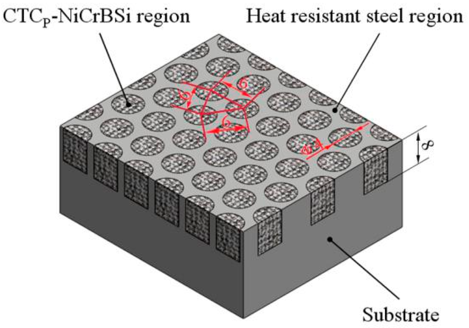
In the present work, a CTCP-NiCrBSi/heat resistant steel composite layer similar to concrete in architecture was designed and fabricated by vacuum fusion sintering. Figure 1 presents the schematic diagram of the composite layer. The CTCP-NiCrBSi/heat resistant steel composite layer was composed of many discrete circular reinforced regions distributed uniformly in the heat resistant steel region. The discrete reinforced region was comprised of the CTCP-NiCrBSi composite. The continuous heat resistant steel region extended down into substrate. In this architectural structure, the discrete CTCP-NiCrBSi regions could better strengthen the layer and the softer continuous heat resistant steel region could better toughen the layer, simultaneously. The effects of CTCP modification on the microstructures and wear behaviors of the CTCP-NiCrBSi/heat resistant steel composite layers are carried out below.
2. Materials and Experimental Procedure
2.1. Raw Materials
Heat resistant steel with a composition of 0.45 wt. % C, 23.50 wt. % Cr, 19.21 wt. % Ni, 1.58 wt. % Si, 1.24 wt. % Mn, and balance Fe was used as the substrate. The matrix of the reinforced regions used was self-fluxing NiCrBSi alloy powder with a size less than 25 μm, whose chemical composition was 0.06 wt. % C, 6.52 wt. % Cr, 3.28 wt. % B, 4.62 wt. % Si, 2.71 wt. % Fe, and Ni in balance. The solidus temperature of the NiCrBSi alloy was 980 °C, and its liquidus temperature was 1050 °C. Typical crushed CTCP with sizes ranging from 40 to 100 μm were used as reinforcement. Some of the CTCP were modified by the carburizing process that involved mixing CTCP with carbon black and heating the mixture at 1550 °C for 90 min in vacuum.
2.2. Fabrication of the Composite Layer
The heat resistant steel substrate with blind holes was machined according to a predetermined design. In the surface layer of the substrate, there were ordered blind holes of 4 mm in diameter, 8 mm in depth and with a fix distance of 6 mm between the holes. Meanwhile, the NiCrBSi alloy powder with 40 vol. % CTCP (unmodified or modified) was mixed for 4 h in a tumbling mixer. Then, the powder mixture was filled in the holes of the substrate and compacted under pressure. Finally, the assembled specimen was put in the vacuum furnace and sintered according to the heating process as follows. First, the specimen was heated to 900 °C with a heating rate of 10 °C/min. Second, the temperature was held for about 30 min to reduce the temperature gradient of the specimen. Third, heating was resumed to the sintered temperature of 1100 °C with a heating rate of 5 °C/min. Finally, the specimen was processed at 1100 °C for 20 min followed by slow cooling within 8 h to room temperature. From Figure 1, it can be seen that the CTCP-NiCrBSi regions occupied about 40 vol. % of the CTCP-NiCrBSi/heat resistant steel composite layer.
2.3. Microstructure Characterization
The microstructures of the CTCP-NiCrBSi regions were observed by means of scanning electron microscope (SEM). Chemical compositions of the phases and elemental distributions of the interfaces were analyzed by utilizing an energy dispersive x-ray spectrometer (EDS, TESCAN, Brno, Czech).
Quantitative image analysis was carried out to measure the area fractions of the microstructure constituents (such as dissolution zone, residual WC/W2C, WC shell, and precipitates) in the CTCP-NiCrBSi regions. Surface areas used for image analysis were randomly chosen, and more than 30 CTCP were included in the selected area to provide statistically meaningful data. The magnification of the images was 500× and the measuring field was 450 × 340 μm in size. Each constituent analysis was repeated four times and the results were averaged. The constituent volume fraction was considered equal to the constituent area fraction determined by image analysis.
To determine the microhardness of different microstructure constituents, HV0.05 (Vickers microhardness tester using a 50-g load for 10 s) was used. The hardness tester was equipped with an optical microscope to allow the user to evaluate in which microstructure constituent the measurement was conducted. The measurement of the hardness values was conducted automatically, but sometimes needed manual adjustment if the indention was not properly detected. At least 16 measurements were conducted on each microstructure constituent at random positions, providing the microhardness values of the different microstructure constituents.
2.4. Abrasion Test
Abrasion tests were conducted in a ring-on-disc rig with interfacial abrasive particles at a temperature range of room temperature (RT) to 800 °C in air. The schematic diagram of the abrasion test rig and the specimens are shown in Figure 2.
The ring material used in this study was high Cr white cast iron with a hardness of HRC55. The disc specimens were made from the CTCP-NiCrBSi/heat resistant steel composite layers. Angular quartz sand (HV980~1100) [15] with a grain size between 180 and 380 μm was used as the abrasive. The ring and disc rotated with a relative speed of 50 rpm (giving a linear speed of 0.04579 m/s) under a load of 20 N. After a wear distance of 82.422 m, the tests were stopped and the mass losses of the disc were measured using an electronic balance with an accuracy of 0.0001 g. From the mass loss of the disc and the length of wear path, wear rate Wa was derived according to the following equation:
where 𝜟m represents the mass loss of the disc; ρp, ρb, and ρm represent the densities of CTCP, NiCrBSi, and heat resistant steel, respectively; α and β represent the volume fraction of CTCP in the CTCP-NiCrBSi region and CTCP-NiCrBSi regions in the composite layer, respectively; and l represents the length of the wear path. Each abrasion test was repeated three times and the wear rate value was averaged.
After the wear tests, the worn surfaces and cross sections of the discs were examined using SEM and EDS.
3. Results and Discussion
3.1. Microstructure of the CTCP-NiCrBSi Region
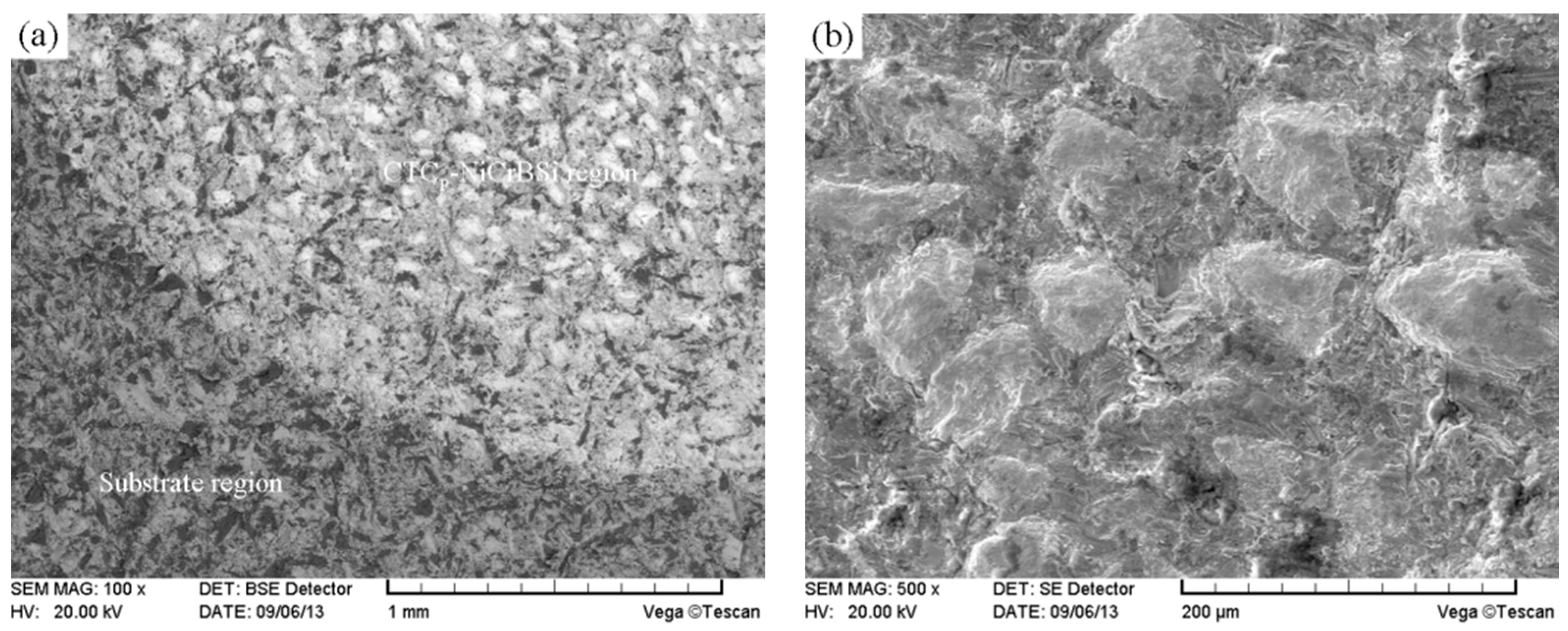
Shrinkage of the powder mixture in the holes led to a wavy surface of the CTCP-NiCrBSi/heat resistant steel composite layer during fusion sintering. Figure 3 shows the macrograph of the CTCP-NiCrBSi/heat resistant steel composite layer fabricated in this study after the wavy surface was planned. It can be seen that the CTCP-NiCrBSi/heat resistant steel composite layer had no obvious defects such as cracks and pores.
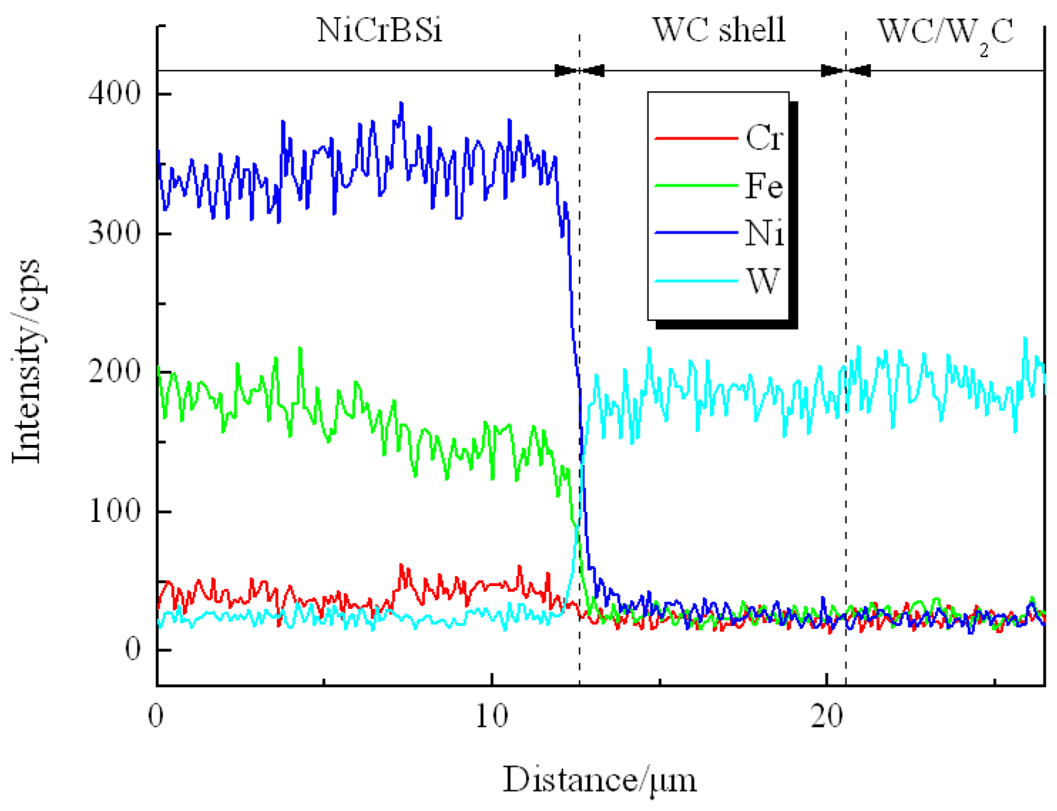
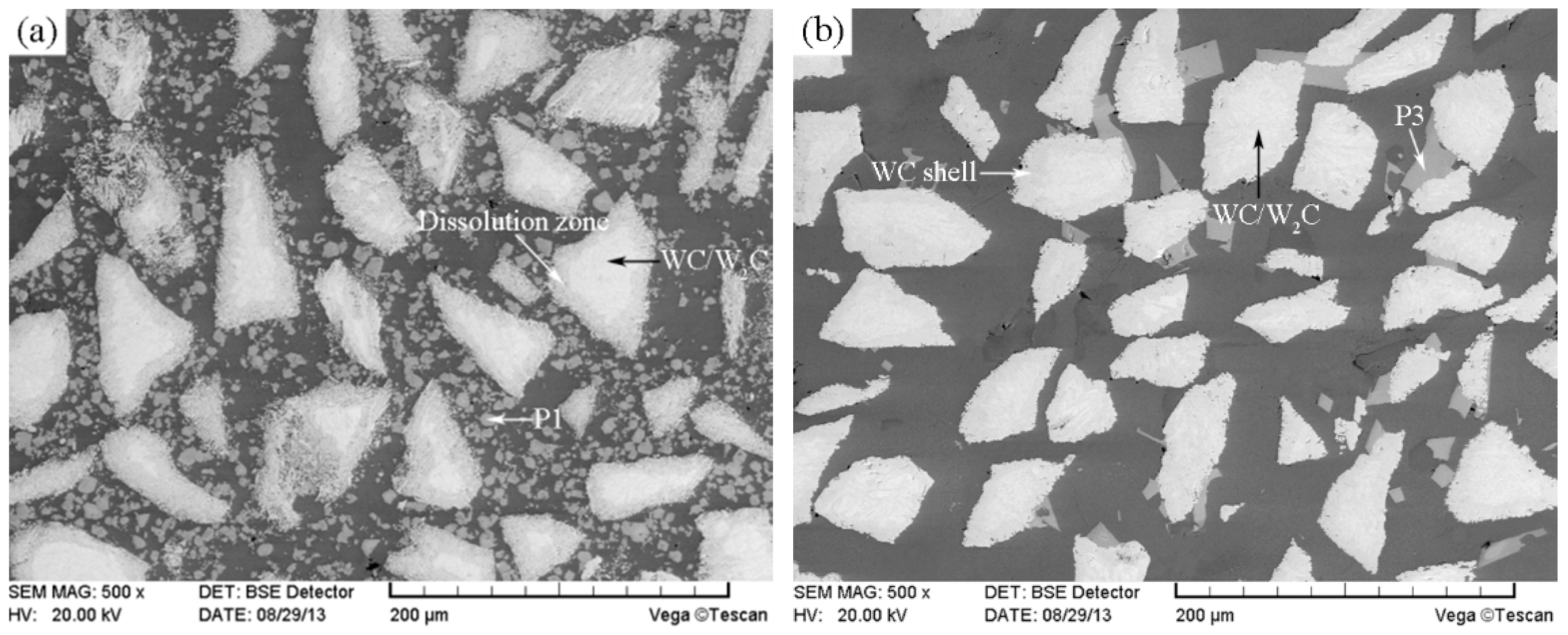
Figure 4 shows the SEM images of the unmodified CTCP-NiCrBSi region in the unmodified CTCP-NiCrBSi/heat resistant steel composite layer. It is evident that the unmodified CTCP displayed considerable dissolution and a small amount of primary CTC was left in the core. A considerable number of blocky precipitates (marked as P1) away from the CTC were formed in the NiCrBSi matrix (Figure 4a). EDS spot analysis confirmed that they were (W, Ni, Cr)-rich carbides. The magnified image shows more details of the CTC and the dissolution zone (Figure 4b). The lamellar dual-phase structure of the CTC can be clearly distinguished where the brighter phase containing approximately 66 at. % W was W2C; and the slightly darker phase containing approximately 50 at. % W was WC. In the dissolution zone, the slightly darker strip phase containing approximately 50 at. % W was WC, which should be the residual phase from the CTC; the darker phase (marked as P2) was (W, Ni)-rich carbide, which should be the reaction product of W2C with a NiCrBSi matrix. The result of the EDS line scan through the dissolution zone is shown in Figure 5 (scanning line see Figure 4a). It can clearly be seen that in the dissolution zone, the Ni, Fe, and Cr contents increased and the W content decreased from CTC to the NiCrBSi matrix and the gradient of concentration was gradual, which indicates that strong elemental diffusion occurred in the dissolution zone.
In the following, we would like to explain the dissolving behavior of CTCP in the NiCrBSi matrix. Figure 6 describes the dissolution mechanism according to the above results. Before vacuum fusion sintering, the CTCP was surrounded by NiCrBSi alloy powder (Figure 6a). During the sintering, the NiCrBSi alloy powder became a liquid phase because of its low melting point, and element interdiffusion occurred between molten NiCrBSi and CTCP. Elements such as Ni, Cr, and Fe diffused from the molten NiCrBSi to CTCP while the W and C diffused in the opposite direction. In the diffusion process, the W2C phase in CTCP reacted with Ni, Cr, and other elements diffusing from the molten matrix to form (W, Ni)-rich carbide, while the WC phase remained mostly intact (Figure 6b). Elements such as Ni, Cr, and Fe in molten NiCrBSi reacted with W and C diffusing from CTCP to form (W, Ni, Cr)-rich carbides, which were precipitated from the melt during subsequent cooling (Figure 6c). This diffusion reaction is similar to the work of Molina [16].
Based on the above analysis, the poor chemical resistance of the W2C phase is responsible for the dissolution of CTCP. The WC phase has a higher chemical resistance than the W2C phase. This suggests that CTCP could be modified by carburizing to produce an outer shell of WC to prevent or reduce dissolution during the deposition. Figure 7 shows the SEM image of the modified CTCP according to the carburizing process mentioned previously. It can be seen that the particle had a core of WC/W2C eutectic surrounded by a slightly darker shell approximately 8 μm in thickness. EDS analysis confirmed that the shell was WC. During the carburizing, the carbon black reacted with the W2C in the CTC, and the W2C was converted to WC which could no longer be distinguished from the original WC phase. Thus, a dense WC shell formed on the CTCP surface.
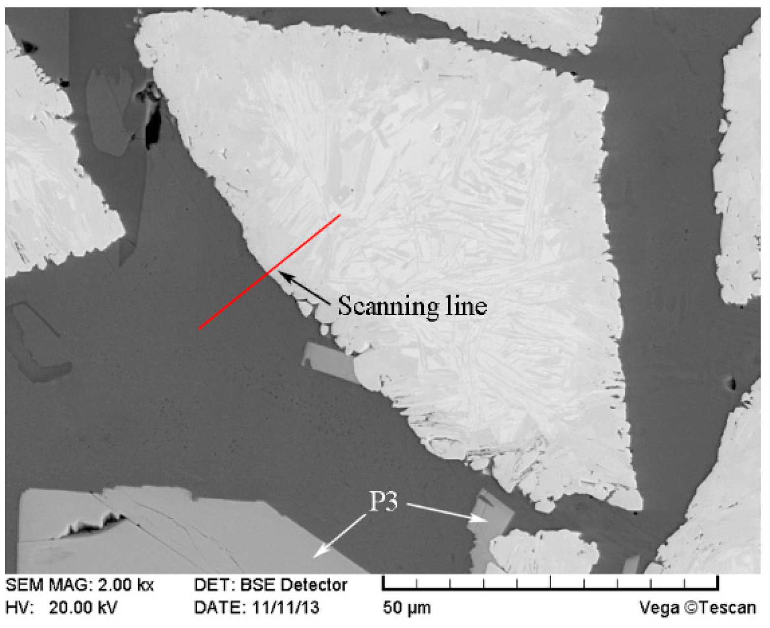
The SEM image of the modified CTCP-NiCrBSi region in the modified CTCP-NiCrBSi/heat resistant steel composite layer is shown in Figure 8. It is evident that the dissolution of the CTCP was largely suppressed. The result of the EDS line scan through the interface between the modified CTCP and NiCrBSi matrix is shown in Figure 9 (scanning line see Figure 8). It is evident that both the outer shell and inner core of the modified CTCP were W-rich with no evidence of nickel. There was a clear boundary between the modified CTCP and the NiCrBSi matrix due to the steep decline in Ni, Fe, and Cr contents and the sharp rise in W content at the interface. A small amount of blocky precipitates (marked as P3) still formed in the matrix. EDS analysis showed that they were also (W, Ni, Cr)-rich carbides which contained more Cr and less W, Ni when compared with that of P1. The formation of P3 might be related to free carbon increasing in the modified CTCP during the carburizing process.
3.2. Volume Fraction and Microhardness of the Microstructure Constituent
The volume fraction and microhardness of the microstructure constituent in CTCP-NiCrBSi region were determined as they are key factors affecting the abrasion resistance of the CTCP-NiCrBSi/heat resistant steel composite layers. Figure 10 shows typical SEM images of the unmodified and the modified CTCP-NiCrBSi regions, which were used for image analysis. It can be seen that the unmodified CTCP displayed excessive dissolution. The microstructure of the unmodified CTCP-NiCrBSi was composed of WC/W2C, dissolution zone, precipitate P1, and the NiCrBSi matrix (Figure 10a). The modified CTCP were not affected by dissolution. The microstructure of the modified CTCP-NiCrBSi was composed of WC/W2C, WC shell, precipitate P3, and the NiCrBSi matrix (Figure 10b). The volume fraction measurement results of the microstructure constituents are listed in Table 1. In the unmodified CTCP-NiCrBSi region, the dissolution zone of the CTCP reached 32.7 vol. % and the residual WC/W2C eutectic left in the cores was only 7.5 vol. % and the blocky precipitate P1 was up to 18.2 vol. %. In the modified CTCP-NiCrBSi region, the WC shell took up 20.1 vol. % and the WC/W2C eutectic occupied 19.5 vol. % and the blocky precipitate P3 was only 3.2 vol. %. Compared with the unmodified CTCP-NiCrBSi region, an increase of about 12.0 vol. % was achieved in the content of the WC/W2C eutectic remaining in the modified CTCP-NiCrBSi region.
The microhardness measurement results of the microstructure constituents are listed in Table 2. It can be observed that the mean microhardness of the WC/W2C eutectic was over HV2200, which was much higher than that of the dissolution zone (HV1488) and the WC shell (HV1577). The mean microhardness of the precipitate P3 was slightly higher than that of the precipitate P1, which may be related to more Cr element in them.
3.3. Interface between CTCP-NiCrBSi and Substrate
Figure 11 shows the SEM images of the interface between the unmodified CTCP-NiCrBSi and the substrate. It can be seen that a transition layer consisting of three zones formed, which indicates the existence of metallurgical bonding in the interface. From the element distribution profile of the interface in Figure 12 (scanning line see Figure 11a), it is clear that there was a gradual increase in the Fe and Cr contents and a gradual decrease in the W content when the location transited from the unmodified CTCP-NiCrBSi to the substrate. This indicates that the dissolution of the substrate and the interdiffusion of elements might take place in the interface. Starting from the unmodified CTCP-NiCrBSi and crossing the transition layer, the first zone (labeled as I) was characterized by the unmodified CTCP being completely dissolved where not only the W2C, but also the WC in CTCP was dissolved. The excessive dissolution of the unmodified CTCP in this zone might have been caused by the increasing content of Cr and Fe elements which are relatively strong carbide formers. The second zone (labeled as I) was narrower and was constituted by a single phase. EDS analysis results indicated that it was a layer of γ-Ni solid solution rich in Fe, Cr. Therefore, the second zone should belong to the isothermally solidified zone. The third zone (labeled as II) was characterized by many precipitating fine granules (Figure 11b). The fine granules were rich in Cr and Fe elements and their microhardness reached HV900. The fine granules could be (Fe, Cr)B precipitates [17]. So, the third zone should belong to the diffusion affected zone. Figure 13 shows the SEM image of the interface between the modified CTCP-NiCrBSi and substrate. It can be seen that the interface also consisted of three zones, but the first zone narrowed down a lot as the modified CTCP had a higher chemical resistance.
Figure 14 describes the physical model of the interface microstructure formation mechanism. The mixture of NiCrBSi and CTCP filled the holes of the substrate and compacted under pressure before the vacuum fusion sintering (Figure 14a). During heating to the sintering temperature, the mixture shrank toward the midsection due to the sintering effects, leaving behind a relatively large channel adjoining the faying surface of the substrate. When the NiCrBSi powder deposited at the mouth of the hole became molten, it was drawn into the gap and flowed toward the bottom of the hole preferentially through the capillary passages in the partially sintered mass of mixture. The large channel adjacent to the faying surface of the substrate was filled after the fine capillary passages in the mixture were filled (Figure 14b). In its wake, the molten NiCrBSi dissolved some of the substrate and element interdiffusion occurred in the interface (Figure 14c). In the CTCP-NiCrBSi zone near the interface, the Fe and Cr elements resulted from the dissolution of the substrate and the diffusion could promote the dissolution of unmodified CTCP, which led to the formation of zone I. As the melting point decreased, elements Si and B diffused outward from the molten NiCrBSi to the substrate, and the melting point of the liquid near the substrate increased, which induced the isothermal solidification resulting in the formation of γ-Ni solid solution layer (zone Ⅱ). Si and B preferred to diffuse along the grain boundaries in the substrate. However, due to the small size of B atoms, the intragranular diffusion of B was essential [18]. As the diffusion continued, the substrate near the interface was enriched with Fe, Cr, and B, so the diffusion affected zone Ⅲ consisting of (Fe,Cr)B precipitates was formed (Figure 14d).
4. Wear Behavior
The wear rates of the CTCP-NiCrBSi/heat resistant steel composite layers investigated at different temperatures are given in Figure 15. It can be seen that the wear rate of the modified CTCP-NiCrBSi/heat resistant steel composite layer was lower than that of the unmodified CTCP-NiCrBSi/heat resistant steel composite layer between RT and 700 °C, and almost equal above 700 °C. The wear rates of both layers decreased with increasing temperature from RT to 700 °C, and increased above 700 °C.
The worn surfaces were observed after the wear tests. As previously mentioned, there were two kinds of regions distributed in the composite layer, namely the continuous substrate region and the discrete CTCP-NiCrBSi regions (Figure 16a). During the abrasion process below 700 °C, the hardness of the substrate region was far lower than that of abrasive and the abrasion loss of the substrate region was larger. In contrast, the abrasion loss of the CTCP-NiCrBSi regions was lower because of the existence of high-hardness CTCP. The abrasive was unable to scratch the CTCP and the wear was concentrated on the NiCrBSi matrix, which led to the protruded CTCP. The protruded CTCP had a protective effect on the NiCrBSi matrix, further on the substrate region (Figure 16b).
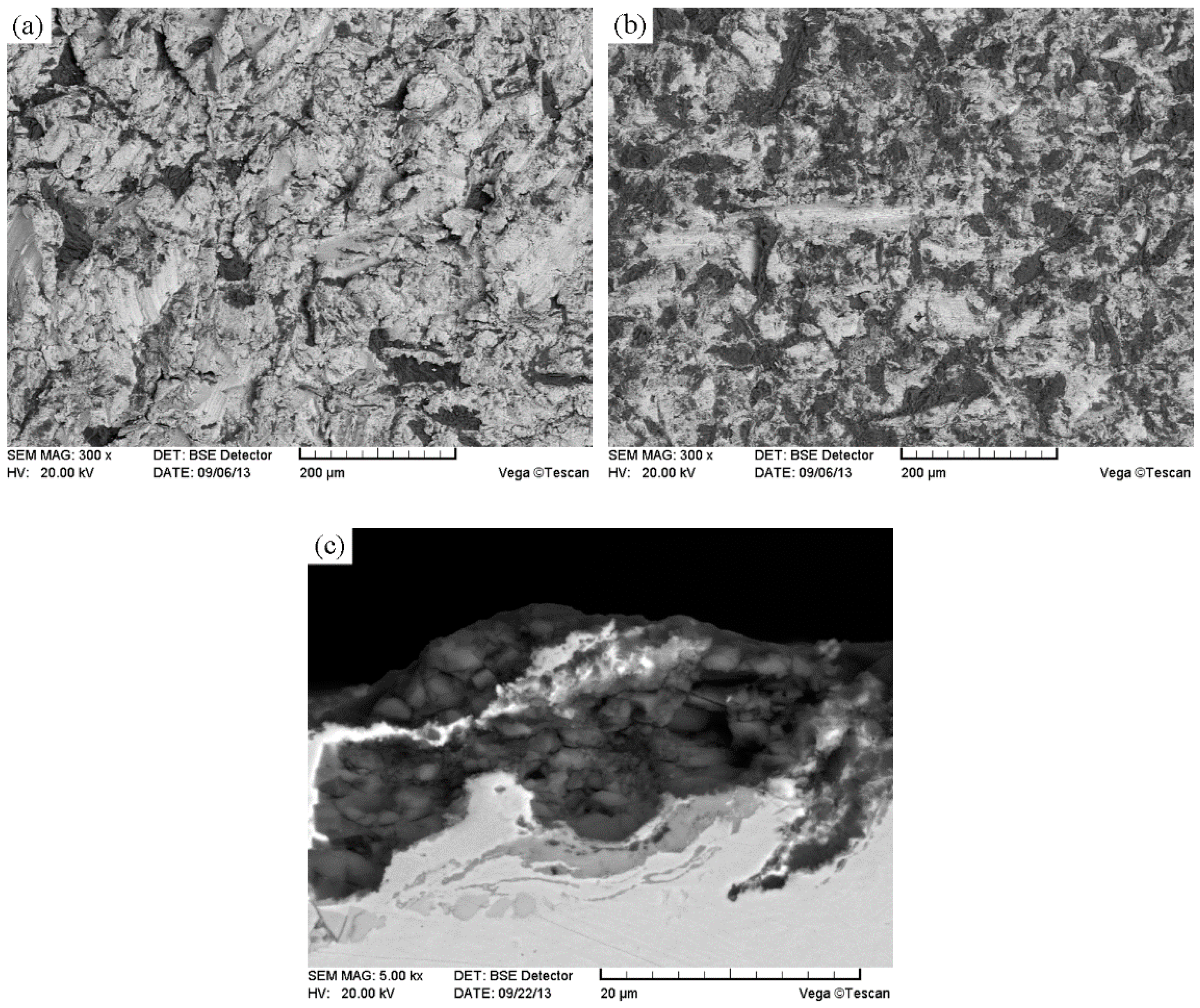
Figure 17 shows typical cross-sections of the CTCP-NiCrBSi regions in composite layers at RT. Similar features were also observed after tests from 200 °C to 700 °C. It can be seen that the unmodified CTCP did not obviously protrude out of the NiCrBSi matrix as there was less WC/W2C left in the core as well as the lower hardness and toughness of the dissolution zone (Figure 17a). Therefore, the protective effect of the unmodified CTCP on the NiCrBSi matrix and substrate region deteriorated. Though a lot of carbides (P1) precipitated in the NiCrBSi matrix because of the dissolution of the CTCP, the carbides in size were too small to reduce abrasion. The modified CTCP obviously protruded out of the NiCrBSi matrix and had a better protective effect on the NiCrBSi matrix and substrate region because more fraction of high hardness WC/W2C was retained (Figure 17b). Therefore, the wear rate of the modified CTCP-NiCrBSi/heat resistant steel composite layer was lower than that of the unmodified CTCP-NiCrBSi/heat resistant steel composite layer between RT and 700 °C.
Comparing the worn surfaces of substrate regions in the composite layers after tests from RT to 700 °C, it can be seen that the amount of attaching abrasive fragments rose with increasing temperature (Figure 18a,b) and laminated structures consisting of abrasive fragments and wear chips formed on the worn surfaces above 400 °C (Figure 18c). These observed features were in agreement with other studies [19,20]. The higher the temperature, the softer the substrate and the more abrasive fragments penetrated the worn surfaces. The formation of the laminated structures could be due to metal chips formed by cutting, which were then compacted back on to the disc [21]. In the CTCP-NiCrBSi regions, only a few abrasive fragments and laminated structures formed in the NiCrBSi areas between the protruding CTCP, which may be due to a higher hot hardness of the NiCrBSi matrix. The abrasive fragments and laminated structures act like hard phases and protect the surfaces against wear. In addition, when the fragments are loose, they may act as a fluidized bed that also reduces friction and wear [22]. Therefore, the wear rates of both composite layers decreased with increasing temperature from RT to 700 °C.
Typical worn surfaces of the modified CTCP-NiCrBSi/heat resistant steel composite layer at 800 °C are illustrated in Figure 19. Similar features were also observed for the unmodified CTCP-NiCrBSi/heat resistant steel composite layer. It can be seen that the white flakes were generated due to CTCP fracture. These wear debris were randomly distributed on the worn surface. The CTCP in SEM high magnification mode showed cracks and pores (Figure 19a). EDS analysis showed that the oxygen concentrated on the surfaces of the CTCP was up to 68.73 at. %, which indicates that excessive oxidation of CTCP occurred. In addition, massive grooves formed on the worn surface of the substrate region (Figure 19b). Below 600 °C, the oxidation of CTCP during the abrasion process in air was moderate [23] so they provided good wear protection. While above 600 °C, the oxidation of CTCP increased rapidly with temperature. The porous oxides offered no resistance to abrasion in air. Additionally, as the depth of the grooves produced by the abrasive particles was larger than the thickness of the laminated structures and the sizes of the abrasive fragments, they were moved from the surface. Therefore, above 700 °C, both the degradation of the CTCP by oxidation and the massive ploughing effects resulting from the softening of the matrix were responsible for the increase of wear rates in Figure 15.
5. Conclusions
1. A CTCP-NiCrBSi/heat resistant steel composite layer with architecture similar to concrete was designed for the toughening layer and fabricated by vacuum fusion sintering, which contained no obvious defects such as cracks and pores.
2. The poor chemical resistance of W2C and the interdiffusion of elements were responsible for the dissolution of unmodified CTCP in the molten NiCrBSi alloy. The W2C in CTCP reacted with Ni and Cr diffusing from molten NiCrBSi to form (W,Ni)-rich carbides, while WC remained mostly intact. Ni, Cr, and Fe in NiCrBSi reacted with W and C diffusing from CTCP to form (W,Ni,Cr)-rich carbides. These (W,Ni,Cr)-rich carbides precipitated from the melt during cooling.
3. The carburized WC outer shell of the modified CTCP could effectively resist the dissolution during vacuum fusion sintering. Compared with unmodified CTCP-NiCrBSi, an increase of about 12.0 vol. % in the content of WC/W2C eutectic remaining in the modified CTCP-NiCrBSi was achieved.
4. The wear rate of the modified CTCP-NiCrBSi/heat resistant steel composite layer was obviously lower than that of the unmodified CTCP-NiCrBSi/heat resistant steel composite layer between RT and 700 °C, and almost equal above 700 °C. The wear rates of both composite layers decreased with increasing temperature from RT to 700 °C and increased above 700 °C.
Author Contributions
Conceptualization, J.Z. and S.H.; Methodology, S.H.; Software, J.Z.; Validation, J.Z. and S.H.; Formal Analysis, J.Z.; Investigation, S.H.; Resources, S.H.; Data Curation, S.H.; Writing—Original Draft Preparation, J.Z.; Writing—Review & Editing, J.Z.; Visualization, S.H.; Supervision, J.Z. and S.H.; Project Administration, J.Z. and S.H.; Funding Acquisition, J.Z. and S.H.
Funding
The authors would like to thank the financial support received for this work by the Chunhui Plan of the Ministry of Education of China under Grant (Z2016127), the Scientific Research Fund of Sichuan Education Department (18ZA0445), the Opening Project of Material Corrosion and Protection Key Laboratory of Sichuan Province (2017CL22), and by the Key Science and Technology Projects of Zigong City (2017XC21).
Conflicts of Interest
The authors declare no conflict of interest.
References
- Berns, H.; Koch, S. Influence of Abrasive Particles on Wear Mechanism and Wear Resistance in Sliding Abrasion Tests at Elevated Temperatures. Wear 1999, 233–235, 424–430. [Google Scholar] [CrossRef]
- Gassmann, R.C. Laser Cladding with (WC+W2C)/Co-Cr-C and (WC+W2C)/Ni-B-Si Composites for Enhanced Abrasive Wear Resistance. Mater. Sci. Technol. 1996, 12, 690–696. [Google Scholar] [CrossRef]
- Harsha, S.; Dwivedi, D.K.; Agarwal, A. Performance of Flame Sprayed Ni-WC Coating under Abrasive Wear Conditions. J. Mater. Eng. Perform. 2008, 17, 104–109. [Google Scholar] [CrossRef]
- Fu, S.; Xu, H. Microstructure and Wear Behavior of (Ti,V)C Reinforced Ferrous Composite. J. Mater. Eng. Perform. 2010, 19, 825–827. [Google Scholar] [CrossRef]
- Garcia-Cordovilla, C.; Narciso, J.; Louis, E. Abrasive Wear Resistance of Aluminium Alloy/ceramic Particulate Composites. Wear 1996, 192, 170–177. [Google Scholar] [CrossRef]
- Zheng, K.; Gao, Y.; Tang, S.; Li, Y.; Ma, S.; Yi, D.; Zhang, Z. Interface Structure and Wear Behavior of Cr26 Ferrous Matrix Surface Composites Reinforced with CTCP. Tribol. Lett. 2014, 54, 15–23. [Google Scholar] [CrossRef]
- Zhou, S.; Dai, X. Laser Induction Hybrid Rapid Cladding of WC Particles Reinforced NiCrBSi Composite Layers. Appl. Surf. Sci. 2010, 256, 4708–4714. [Google Scholar] [CrossRef]
- Zhou, S.; Zeng, X.; Hu, Q.; Huang, Y. Analysis of Crack Behavior for Ni-based WC Composite Layers by Laser Cladding and Crack-free Realization. Appl. Surf. Sci. 2008, 255, 1646–1653. [Google Scholar] [CrossRef]
- Pandey, A.B.; Majumdar, B.S.; Miracle, D.B. Laminated Particulate-reinforced Aluminum Composites with Improved Toughness. Acta. Mater. 2001, 49, 405–417. [Google Scholar]
- Qin, S.; Zhang, G. Preparation of High Fracture Performance SiCp-6061A1/6061A1 Composite. Mater. Sci. Eng. A 2000, 279, 231–236. [Google Scholar] [CrossRef]
- Jamali, M.; Farokhzadeh, K.; Bagheri, R.; Seyed Reihani, S.M. Architecturally Modified Al-DRA Composites: The Effect of Size and Shape of the DRA Rods on Fracture Behavior. J. Mater. Sci. 2010, 45, 2852–2861. [Google Scholar] [CrossRef]
- Hou, S.; Bao, C.; Zhang, Z.; Bai, Y. Microstructure and Wear Behavior of High-Cr WCI Matrix Surface Composite Reinforced with Cemented Carbide Rods. J. Mater. Eng. Perform. 2013, 22, 2064–2072. [Google Scholar] [CrossRef]
- Gerk, C.; Wernicke, K.-D. Dual-phase Hard Material Comprising Tungsten Carbide, Process for the Production Thereof and Its Use. U.S. Patent 7541090B2, 2 June 2009. [Google Scholar]
- Jones, M.; Waag, U. The Influence of Carbide Dissolution on the Erosion-corrosion Properties of Cast Tungsten Carbide/Ni-based PTAW Overlays. Wear 2011, 271, 1314–1324. [Google Scholar] [CrossRef]
- Yi, D.; Xing, J.; Ma, S.; Fu, H.; Chen, W.; Li, Y.; Yan, J.; Zhang, J.; Liu, Z.; Zhu, J. Three-body Abrasive Wear Behavior of Low Carbon Fe-B Cast Alloy and Its Microstructures under Different Casting processes. Tribol. Lett. 2011, 42, 67–77. [Google Scholar] [CrossRef]
- Molina, J.M.; Saravanan, R.A.; Narciso, J.; Louis, E. Surface Modification of 2014 Aluminium Alloy–Al2O3 Particles Composites by Nickel Electrochemical Deposition. Mater. Sci. Eng. A 2004, 383, 299–306. [Google Scholar] [CrossRef]
- Wu, N.; Li, Y.; Wang, J. Microstructure of Ni-NiCr Laminated Composite and Cr18-Ni8 steel Joint by Vacuum Brazing. Vacuum 2012, 86, 2059–2063. [Google Scholar] [CrossRef]
- Yuan, X.; Kang, C.Y.; Kim, M.B. Microstructure and XRD Analysis of Brazing Joint for Duplex Stainless Steel Using a Ni-Si-B Filler Metal. Mater. Charact. 2009, 60, 923–931. [Google Scholar] [CrossRef]
- Fischer, A. Mechanisms of High Temperature Sliding Abrasion of Metallic Materials. Wear 1992, 152, 151–159. [Google Scholar] [CrossRef]
- Winkelmann, H.; Badisch, E.; Varga, M.; Danninger, H. Wear Mechanisms at High Temperatures. Part 3: Changes of the Wear Mechanism in the Continuous Impact Abrasion Test with Increasing Testing Temperature. Tribol. Lett. 2010, 37, 419–429. [Google Scholar] [CrossRef]
- Venicatesan, K.; Subramanian, C.; Surnmerville, E. Three-body Abrasion of Surface Engineered Die Steel at Elevated Temperatures. Wear 1997, 203–204, 129–138. [Google Scholar] [CrossRef]
- Duarte, M.; Vragovic, I.; Molina, J.M.; Prieto, R.; Narciso, J.; Louis, E. 1/f Noise in Sliding Friction under Wear Conditions: The Role of Debris. Phys. Rev. Lett. 2009, 102, 045501. [Google Scholar] [CrossRef] [PubMed]
- Berns, H.; Koch, S. High Temperature Sliding Abrasion of a Nickel-base Alloy and Composite. Wear 1999, 225–229, 154–162. [Google Scholar] [CrossRef]
Figure 1.
Schematic diagram of the CTCP-NiCrBSi/heat resistant steel composite layer (Dimensions are in mm).
Figure 1.
Schematic diagram of the CTCP-NiCrBSi/heat resistant steel composite layer (Dimensions are in mm).

Figure 2.
Schematic diagram of the abrasion test rig and the specimens (Dimensions are in mm).
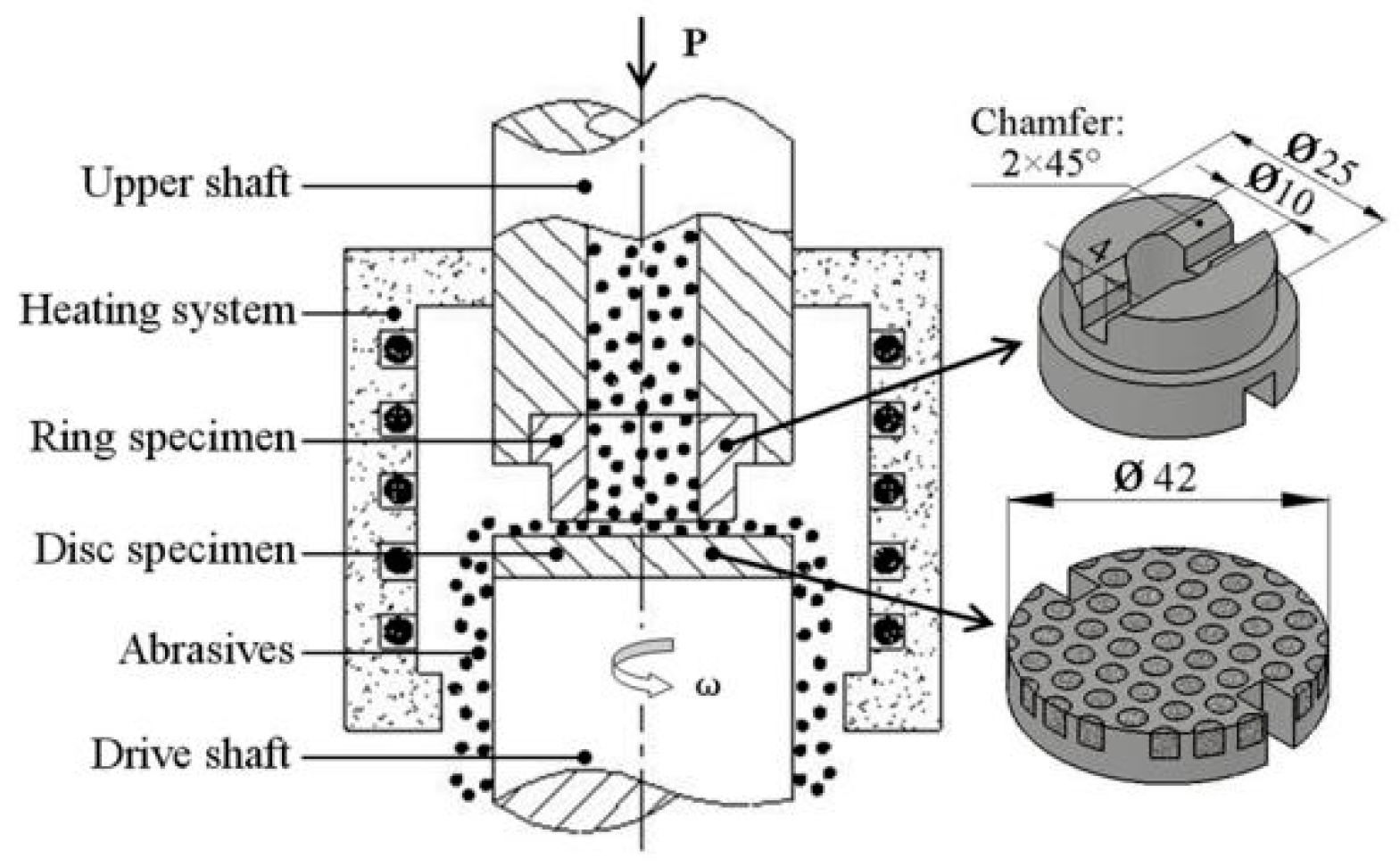
Figure 3.
Macrograph of the CTCP-NiCrBSi/heat resistant steel composite layer fabricated.

Figure 4.
(a) SEM image of the unmodified CTCP-NiCrBSi, and (b) magnified SEM image of the zone “A” in (a).
Figure 4.
(a) SEM image of the unmodified CTCP-NiCrBSi, and (b) magnified SEM image of the zone “A” in (a).
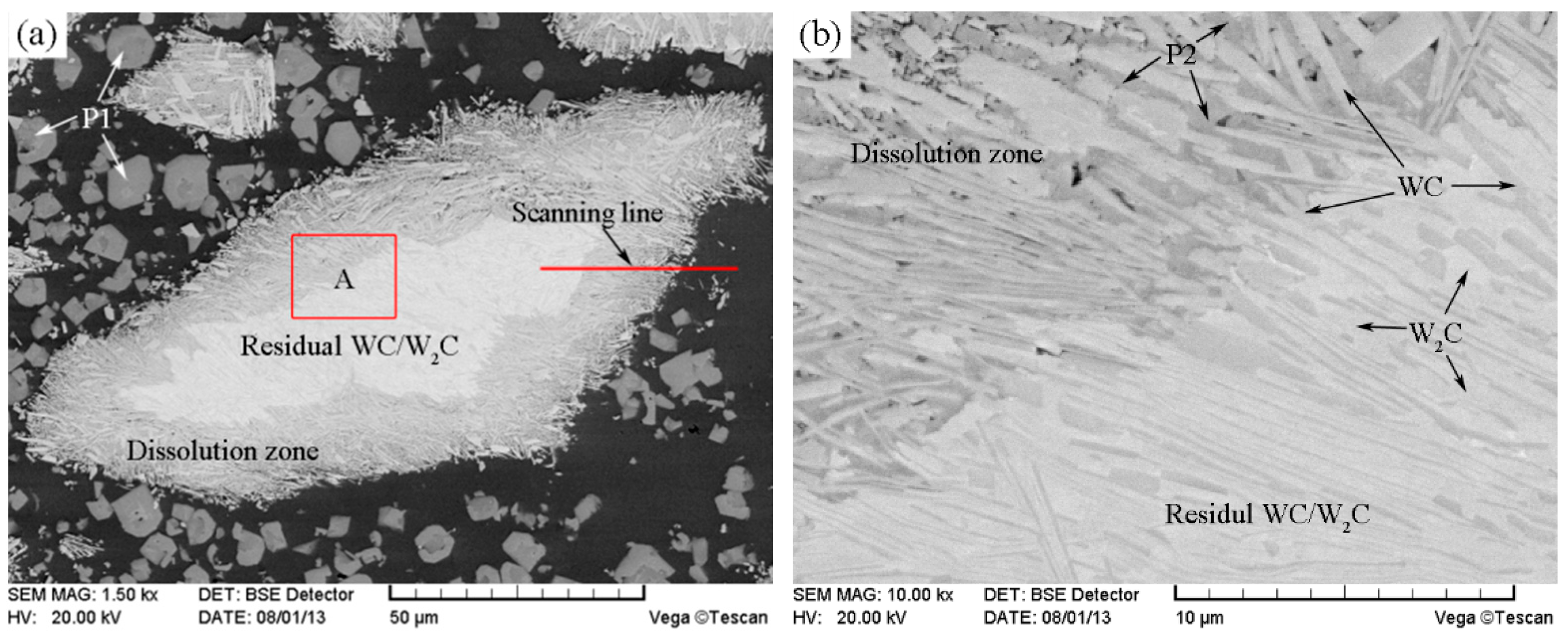
Figure 5.
EDS line scan from unmodified CTCP to NiCrBSi.
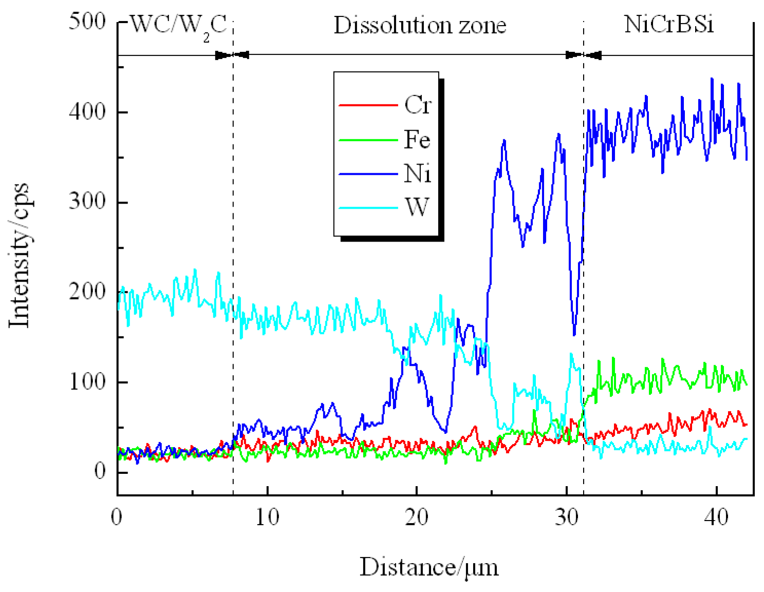
Figure 6.
Dissolution schematic diagram of the unmodified CTCP in NiCrBSi alloy: (a) Before sintering; (b) Interdiffusion of elements and (W, Ni)-rich carbide forming; (c) (W, Ni, Cr)-rich carbide precipitating.
Figure 6.
Dissolution schematic diagram of the unmodified CTCP in NiCrBSi alloy: (a) Before sintering; (b) Interdiffusion of elements and (W, Ni)-rich carbide forming; (c) (W, Ni, Cr)-rich carbide precipitating.
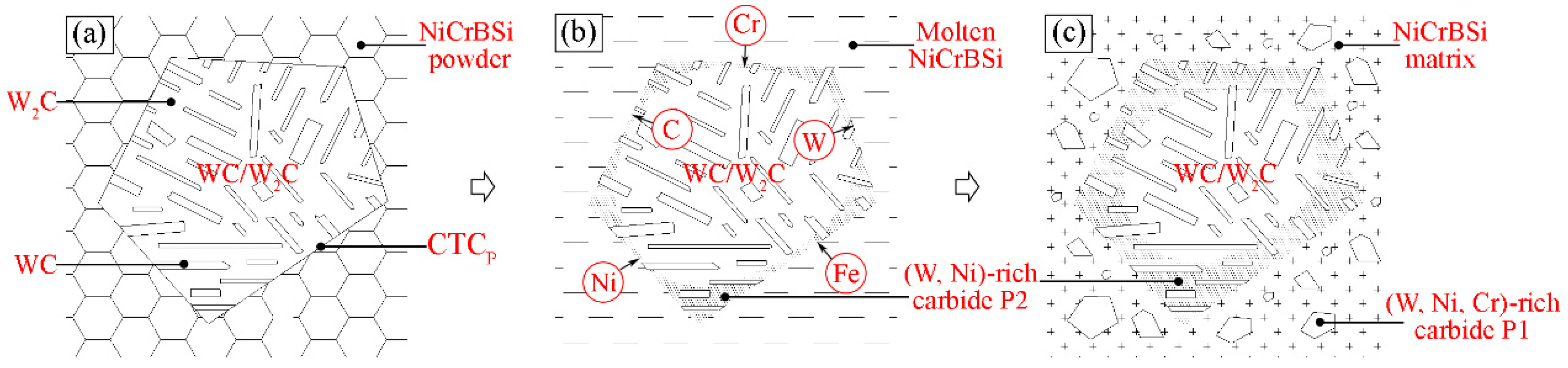
Figure 7.
SEM image of the modified CTCP.
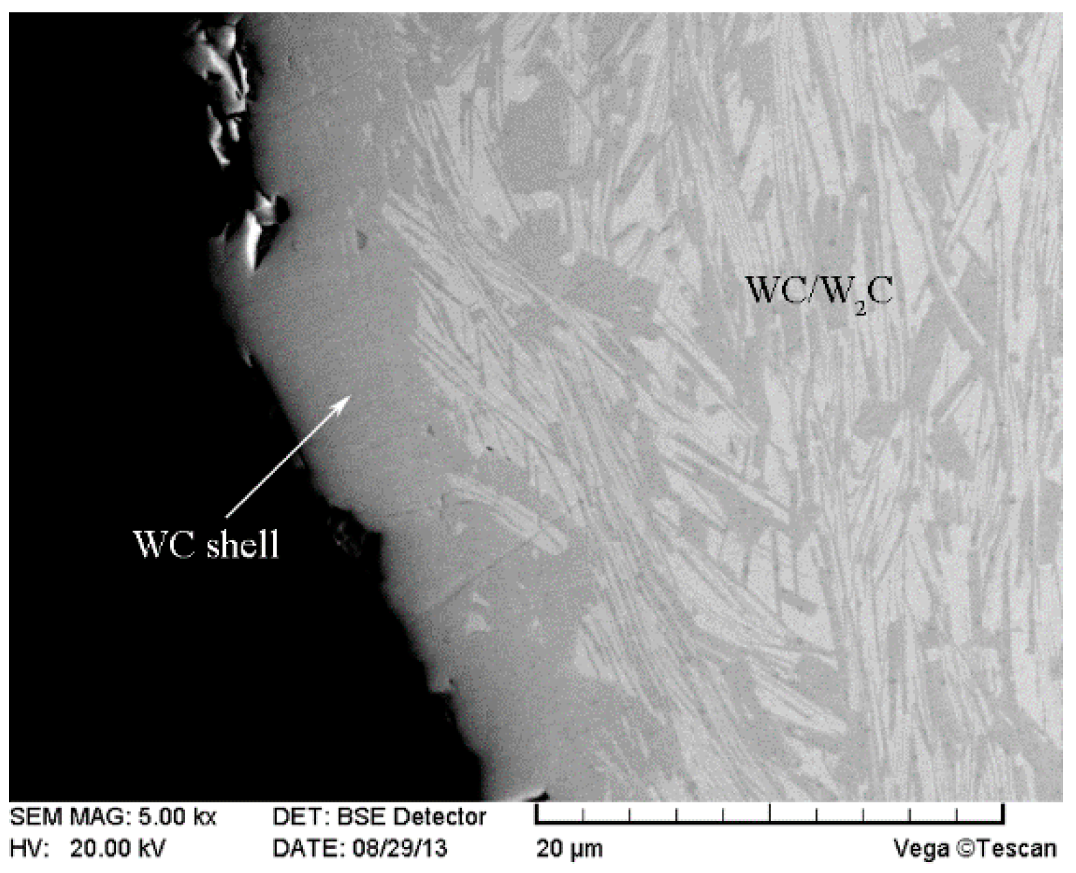
Figure 8.
SEM image of the modified CTCP-NiCrBSi.

Figure 9.
EDS line scan from NiCrBSi to the modified CTCP.

Figure 10.
Typical SEM images of (a) the unmodified, and (b) the modified CTCP-NiCrBSi used for quantitative image analysis.
Figure 10.
Typical SEM images of (a) the unmodified, and (b) the modified CTCP-NiCrBSi used for quantitative image analysis.

Figure 11.
(a) SEM image of the interface between unmodified CTCP-NiCrBSi and substrate and (b) magnified SEM image of the zone “A” in (a).
Figure 11.
(a) SEM image of the interface between unmodified CTCP-NiCrBSi and substrate and (b) magnified SEM image of the zone “A” in (a).
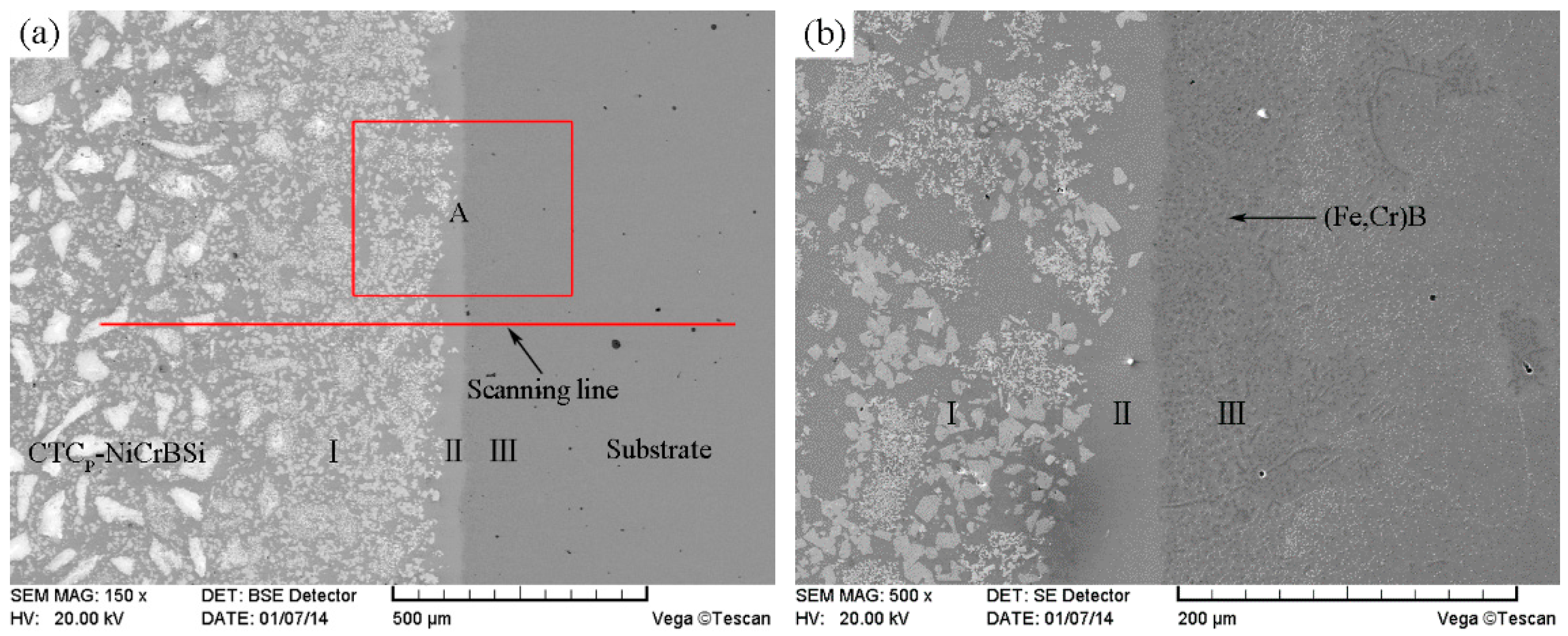
Figure 12.
EDS line scan from unmodified CTCP-NiCrBSi to substrate.

Figure 13.
SEM image of the interface between modified CTCP-NiCrBSi and substrate.
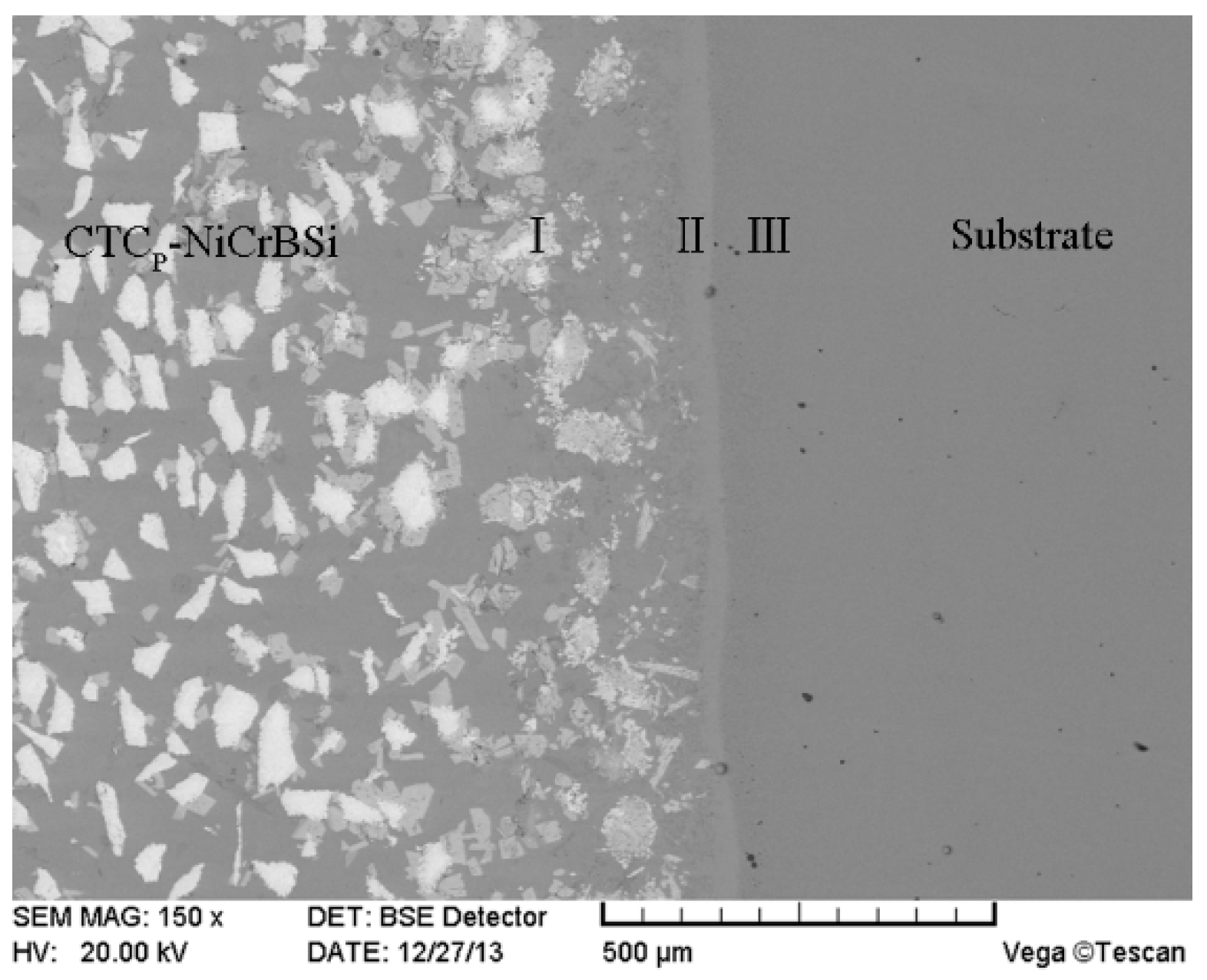
Figure 14.
Formation schematic diagram of the interface between CTCP-NiCrBSi and substrate: (a) before sintering; (b) sintering shrinkage and molten NiCrBSi filling channel; (c) elements interdiffusion, CTCP dissolution, isothermal solidification, and (Fe,Cr)B precipitation; and (d) interface formation.
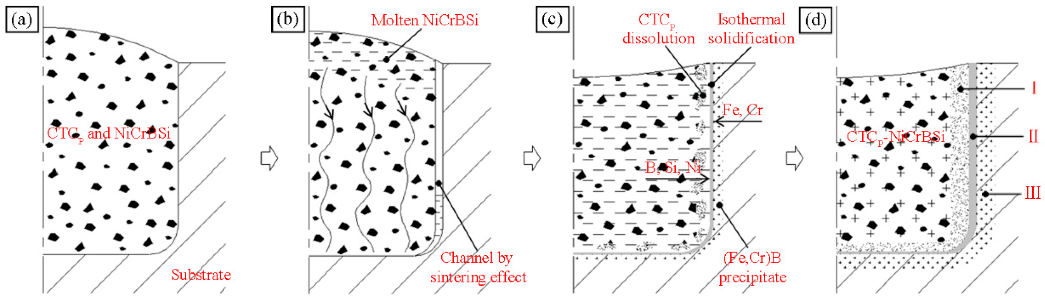
Figure 15.
Wear rates of the CTCP-NiCrBSi/heat resistant steel composite layers as a function of testing temperature.
Figure 15.
Wear rates of the CTCP-NiCrBSi/heat resistant steel composite layers as a function of testing temperature.
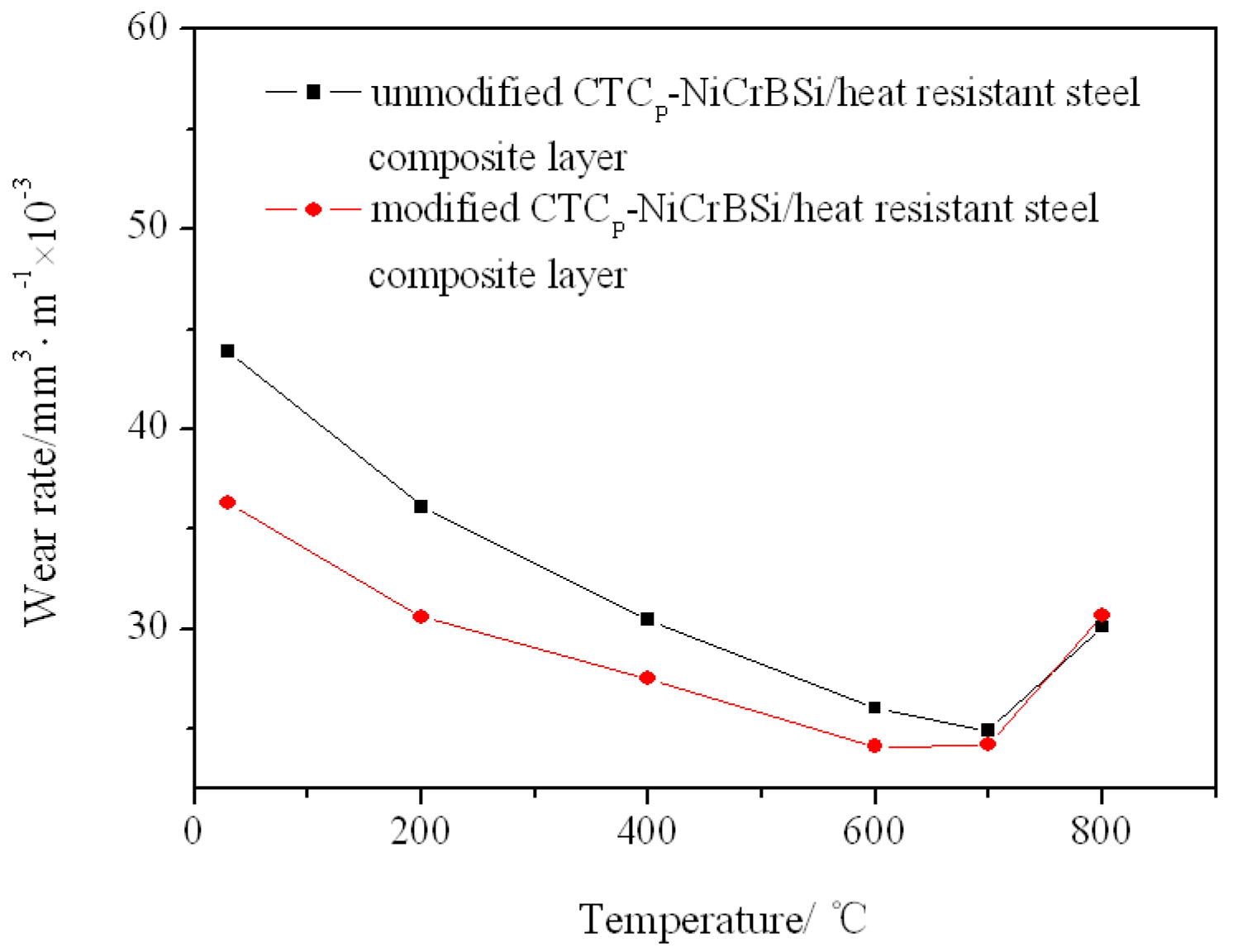
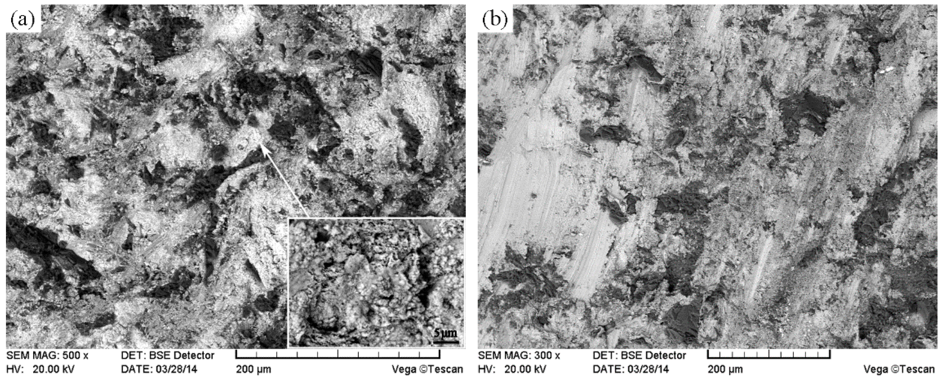
Figure 16.
(a) Worn surface morphology of the modified CTCP-NiCrBSi/heat resistant steel composite layer, and (b) magnified worn surface morphology of the CTCP-NiCrBSi region at 600 °C.
Figure 16.
(a) Worn surface morphology of the modified CTCP-NiCrBSi/heat resistant steel composite layer, and (b) magnified worn surface morphology of the CTCP-NiCrBSi region at 600 °C.

Figure 17.
Cross-sections morphologies of (a) the unmodified, and (b) the modified CTCP-NiCrBSi at RT.
Figure 17.
Cross-sections morphologies of (a) the unmodified, and (b) the modified CTCP-NiCrBSi at RT.
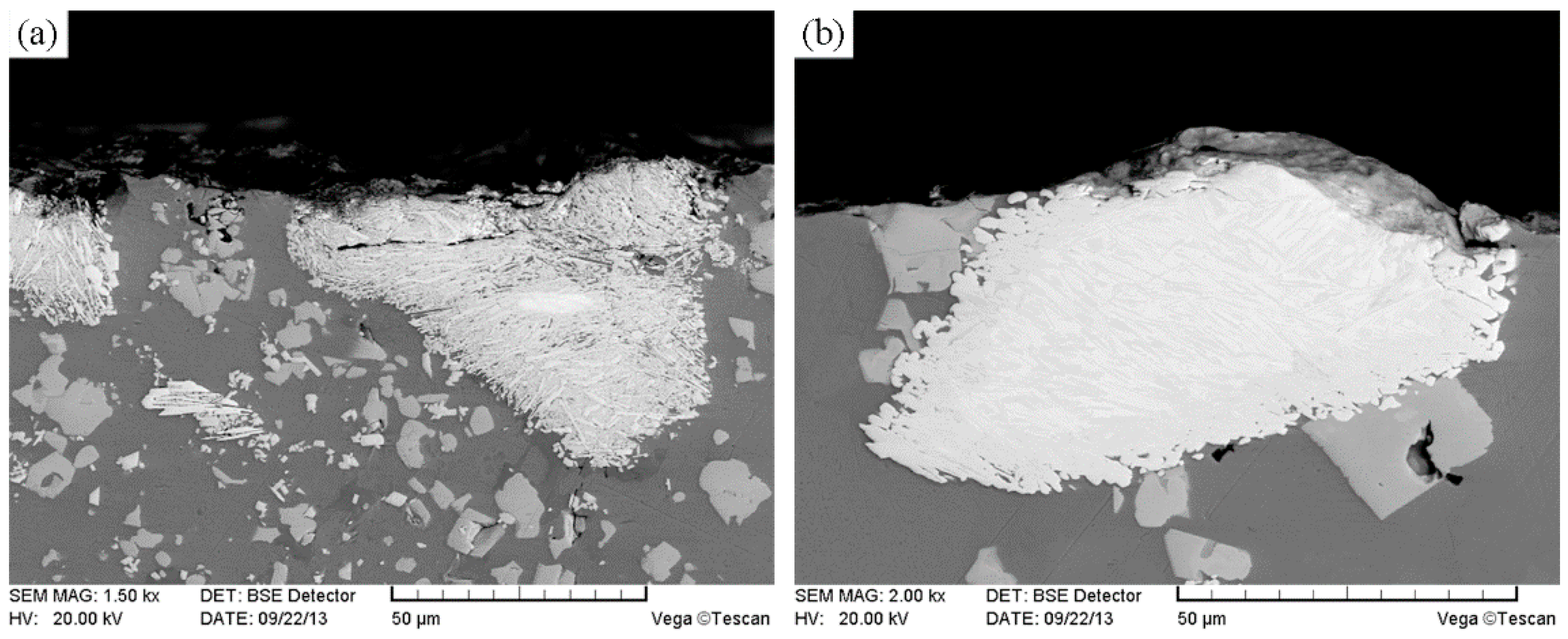
Figure 18.
Worn surface morphologies of the substrate regions: (a) at RT; (b) at 600 °C; and (c) cross-section morphology of the substrate region at 600 °C.
Figure 18.
Worn surface morphologies of the substrate regions: (a) at RT; (b) at 600 °C; and (c) cross-section morphology of the substrate region at 600 °C.

Figure 19.
Worn surface morphologies of the modified CTCP-NiCrBSi/heat resistant steel composite layer at 800 °C: (a) CTCP-NiCrBSi region, and (b) substrate region.
Figure 19.
Worn surface morphologies of the modified CTCP-NiCrBSi/heat resistant steel composite layer at 800 °C: (a) CTCP-NiCrBSi region, and (b) substrate region.


Table 1.
Volume fraction of the microstructure constituent in CTCP-NiCrBSi.
| CTCP-NiCrBSi Regions | Constituent Content (vol. %) | |||||
|---|---|---|---|---|---|---|
| WC/W2C | Dissolution Zone | WC Shell | P1 | P3 | NiCrBSi Matrix | |
| Unmodified | 7.5 | 32.7 | - | 18.2 | - | balance |
| Modified | 19.5 | - | 20.1 | - | 3.2 | balance |
Table 2.
Microhardness of the microstructure constituent in CTCP-NiCrBSi.
| CTCP-NiCrBSi Regions | Constituent Microhardness, HV | ||||
|---|---|---|---|---|---|
| WC/W2C | Dissolution Zone | WC Shell | P1 | P3 | |
| Unmodified | 2256 | 1488 | - | 1084 | - |
| Modified | 2231 | - | 1577 | - | 1262 |
© 2018 by the authors. Licensee MDPI, Basel, Switzerland. This article is an open access article distributed under the terms and conditions of the Creative Commons Attribution (CC BY) license (http://creativecommons.org/licenses/by/4.0/).
Share and Cite
MDPI and ACS Style
Zhang, J.; Hou, S. Effects of CTCP Modification on Microstructure and Wear Behavior of CTCP-NiCrBSi/Heat Resistant Steel Composite Layer. Materials 2018, 11, 2202. https://doi.org/10.3390/ma11112202
AMA Style
Zhang J, Hou S. Effects of CTCP Modification on Microstructure and Wear Behavior of CTCP-NiCrBSi/Heat Resistant Steel Composite Layer. Materials. 2018; 11(11):2202. https://doi.org/10.3390/ma11112202
Chicago/Turabian StyleZhang, Jianjun, and Shuzeng Hou. 2018. "Effects of CTCP Modification on Microstructure and Wear Behavior of CTCP-NiCrBSi/Heat Resistant Steel Composite Layer" Materials 11, no. 11: 2202. https://doi.org/10.3390/ma11112202
Note that from the first issue of 2016, this journal uses article numbers instead of page numbers. See further details here.