Multiscale Analysis of the Microstructure and Stress Evolution in Cold Work Die Steel during Deep Cryogenic Treatment


Abstract
:
1. Introduction
2. Experimental Procedures
3. Multiscale Numerical Procedure
4. Results and Discussion
5. Conclusions
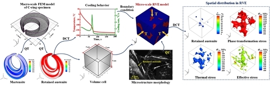
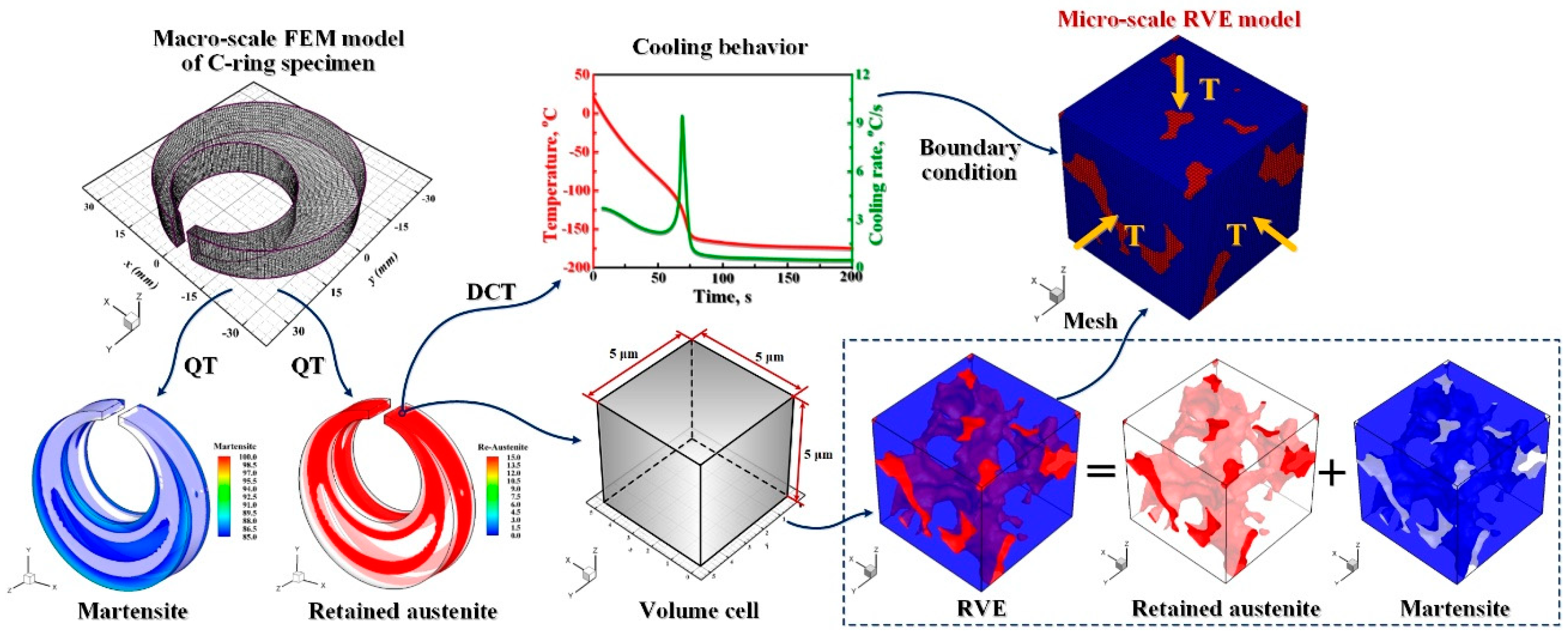
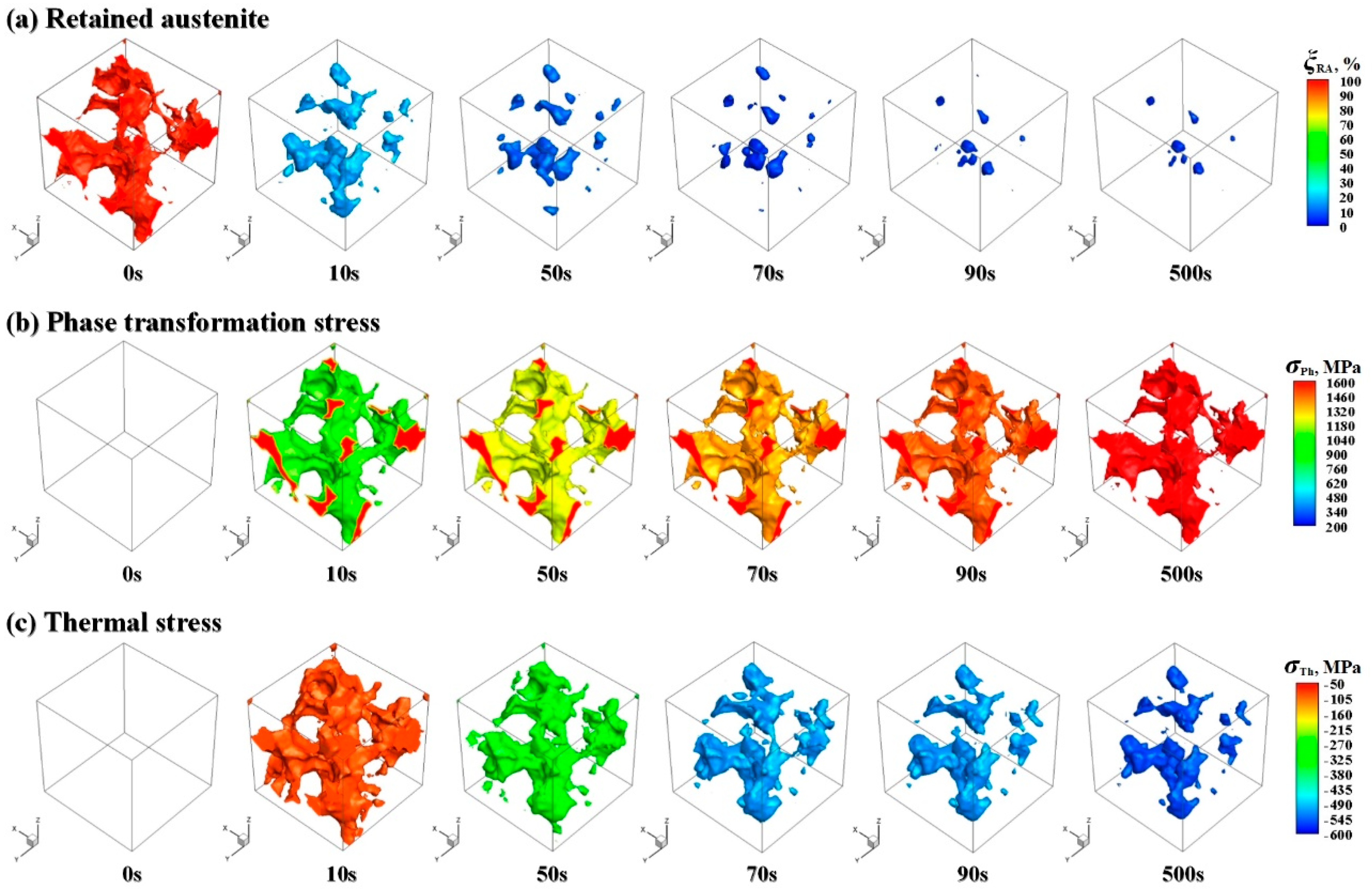
- After cooling to near −160 °C of DCT, the largest intensity of martensite is formed, but the retained austenite has not been eliminated completely until the end of DCT and there still exist almost 3% of retained austenite in RVE.
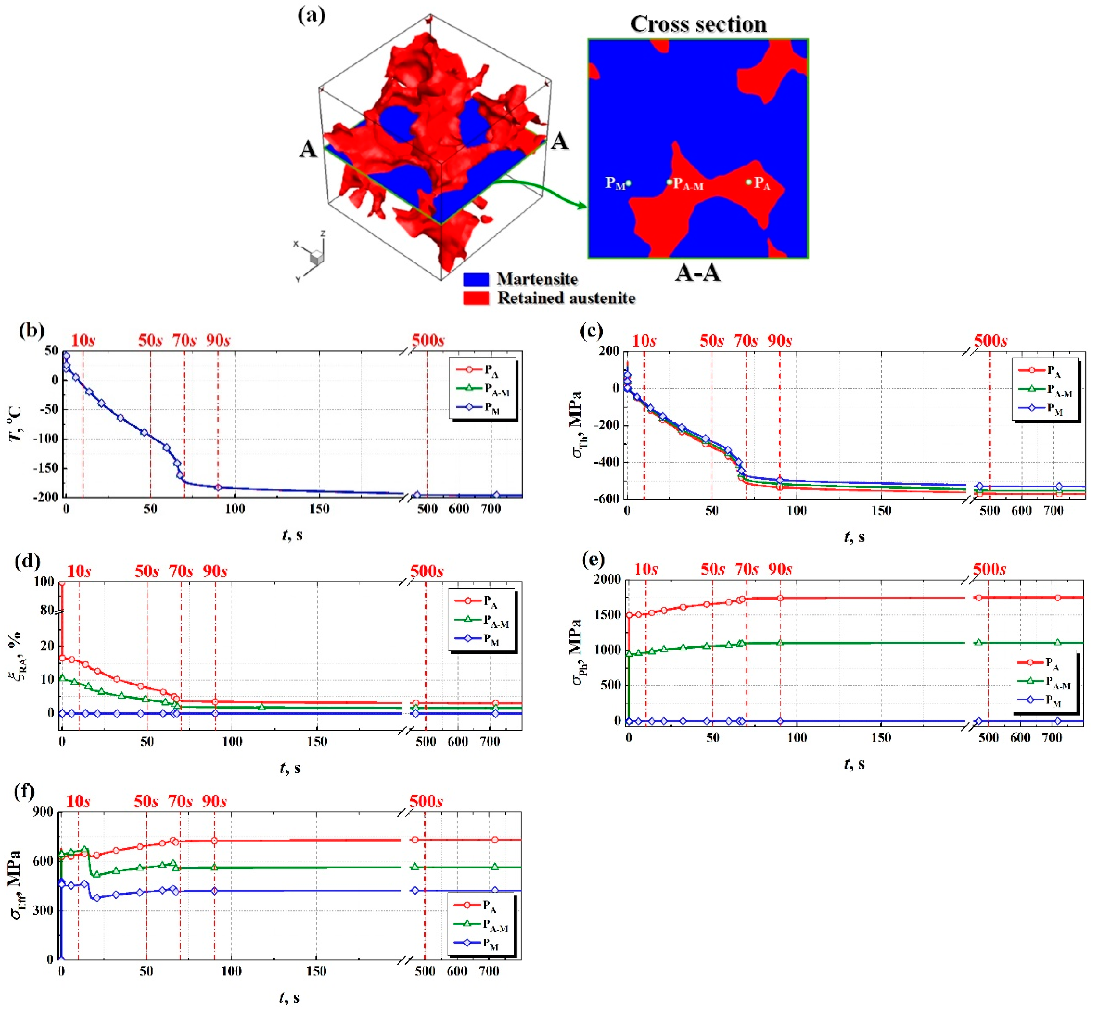
- The driving force for the precipitation of fine and uniform carbides during DCT is provided by the competition between the thermal and phase transformation stresses. After DCT, the mean phase transformation stresses inside retained austenite grain and at the interface between retained austenite and martensite in RVE are almost up to 1500 MPa. While, the amplitude of thermal stress is significantly smaller and only about 1/3 of the phase transformation stress. Compared with the thermal stress, the phase transformation stress during DCT plays a more significant role.
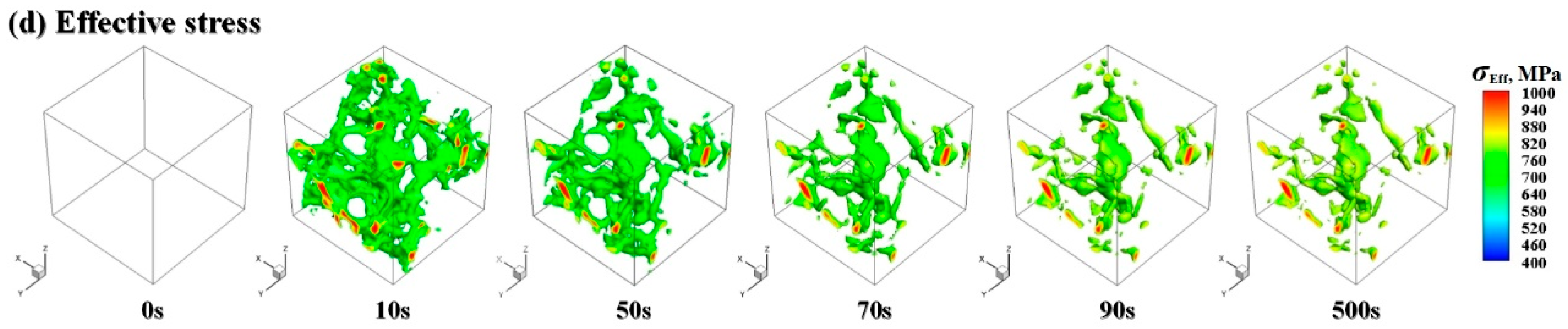
- During DCT, the maximum value of effective stress in RVE even exceeds 1000 MPa, which may provide a required driving force for the precipitation of fine carbide particles during DCT. The above quantitative findings can provide valuable insights for better understanding of the underlying mechanism of DCT and support its further quantitative analysis.
Author Contributions
Funding
Conflicts of Interest
References
- Kalsi, N.S.; Sehgal, R.; Sharma, V.S. Cryogenic treatment of tool materials: A review. Mater. Manuf. Process. 2010, 25, 1077–1100. [Google Scholar] [CrossRef]
- Gill, S.S.; Singh, H.; Singh, R.; Singh, J. Cryoprocessing of cutting tool materials—A review. Int. J. Adv. Manuf. Technol. 2010, 48, 175–192. [Google Scholar] [CrossRef]
- Gu, K.X.; Zhao, B.; Weng, Z.J.; Wang, K.K.; Cai, H.K.; Wang, J.J. Microstructure evolution in metastable β titanium alloy subjected to deep cryogenic treatment. Mater. Sci. Eng. A 2018, 723, 157–164. [Google Scholar] [CrossRef]
- Das, D.; Dutta, A.K.; Toppo, V.; Ray, K.K. Effect of deep cryogenic treatment on the carbide precipitation and tribological behavior of D2 steel. J. Mater. Manuf. Process. 2007, 22, 474–480. [Google Scholar] [CrossRef]
- Wang, K.K.; Tan, Z.L.; Gu, K.X.; Gao, B.; Gao, G.H.; Misra, R.D.K.; Bai, B.Z. Effect of deep cryogenic treatment on structure-property relationship in an ultrahigh strength Mn-Si-Cr bainite/martensite multiphase rail steel. Mater. Sci. Eng. A 2017, 684, 559–566. [Google Scholar] [CrossRef]
- Li, S.H.; Xie, Y.Z.; Wu, X.C. Hardness and toughness investigations of deep cryogenic treated cold work die steel. Cryogenics 2010, 50, 89–92. [Google Scholar] [CrossRef]
- Ptačinová, J.; Sedlická, V.; Hudáková, M.; Dlouhý, I.; Jurči, P. Microstructure-toughness relationships in sub-zero treated and tempered Vanadis 6 steel compared to conventional treatment. Mater. Sci. Eng. A 2017, 702, 241–258. [Google Scholar] [CrossRef]
- Surberg, C.H.; Stratton, P.; Lingenhöle, K. The effect of some heat treatment parameters on the dimensional stability of AISI D2. Cryogenics 2008, 48, 42–47. [Google Scholar] [CrossRef]
- Nazarian, H.; Krol, M.; Pawlyta, M.; Vahdat, S.E. Effect of sub-zero treatment on fatigue strength of aluminum 2024. Mater. Sci. Eng. A 2018, 710, 38–46. [Google Scholar] [CrossRef]
- Araghchi, M.; Mansouri, H.; Vafaei, R.; Guo, Y.N. A novel cryogenic treatment for reduction of residual stresses in 2024 aluminum alloy. Mater. Sci. Eng. A 2017, 689, 48–52. [Google Scholar] [CrossRef]
- Li, H.Z.; Tong, W.P.; Cui, J.J.; Zhang, H.; Chen, L.Q.; Zuo, L. The influence of deep cryogenic treatment on the properties of high-vanadium alloy steel. Mater. Sci. Eng. A 2016, 662, 356–362. [Google Scholar] [CrossRef]
- Li, J.J.; Yan, X.G.; Liang, X.Y.; Guo, H.; Li, D.Y. Influence of different cryogenic treatments on high-temperature wear behavior of M2 steel. Wear 2017, 376–377, 1112–1121. [Google Scholar] [CrossRef]
- Podgornik, B.; Paulin, I.; Zajec, B.; Jacobson, S.; Leskovšek, V. Deep cryogenic treatment of tool steels. J. Mater. Process. Technol. 2016, 229, 398–406. [Google Scholar] [CrossRef]
- Wang, K.K.; Gu, K.X.; Miao, J.H.; Weng, Z.J.; Wang, J.J.; Tan, Z.L.; Bai, B.Z. Toughening optimization on a low carbon steel by a novel Quenching-Partitioning-Cryogenic-Tempering treatment. Mater. Sci. Eng. A 2018. [Google Scholar] [CrossRef]
- Pérez, M.; Belzunce, F.J. The effect of deep cryogenic treatments on the mechanical properties of an AISI H13 steel. Mater. Sci. Eng. A 2015, 624, 32–40. [Google Scholar] [CrossRef]
- Bensely, A.; Shyamala, L.; Harish, S.; Mohan Lal, D.; Nagarajan, G.; Junik, K.; Rajadurai, A. Fatigue behavior and fracture mechanism of cryogenically treated En 353 steel. Mater. Des. 2009, 30, 2955–2962. [Google Scholar] [CrossRef]
- Senthilkumar, D.; Rajendran, I.; Pellizzari, M.; Siiriainen, J. Influence of shallow and deep cryogenic treatment on the residual state of stress of 4140 steel. J. Mater. Process. Technol. 2011, 211, 396–401. [Google Scholar] [CrossRef]
- Zhirafar, S.; Rezaeian, A.; Pugh, M. Effect of cryogenic treatment on the mechanical properties of 4340 steel. J. Mater. Process. Technol. 2007, 186, 298–303. [Google Scholar] [CrossRef]
- Das, D.; Dutta, A.K.; Ray, K.K. On the refinement of carbide precipitates by cryotreatment in AISI D2 steel. Philos. Mag. 2009, 89, 55–76. [Google Scholar] [CrossRef]
- Gavriljuk, V.G.; Theisen, W.; Sirosh, V.V.; Polshin, E.V.; Kortmann, A.; Mogilny, G.S.; Petrov, Y.N.; Tarusin, Y.V. Low-temperature martensitic transformation in tool steels in relation to their deep cryogenic treatment. Acta Mater. 2013, 61, 1705–1715. [Google Scholar] [CrossRef]
- Li, S.H.; Xiao, M.G.; Ye, G.M.; Zhao, K.Y.; Yang, M.S. Effects of deep cryogenic treatment on microstructural evolution and alloy phases precipitation of a new low carbon martensitic stainless bearing steel during aging. Mater. Sci. Eng. A 2018, 732, 167–177. [Google Scholar] [CrossRef]
- Li, H.P.; Zhao, G.Q.; Niu, S.T.; Huang, C.Z. FEM simulation of quenching process and experimental verification of simulation results. Mater. Sci. Eng. A 2007, 452–453, 705–714. [Google Scholar]
- Jung, M.; Kang, M.; Lee, Y.K. Finite-element simulation of quenching incorporating improved transformation kinetics in a plain medium-carbon steel. Acta Mater. 2012, 60, 525–536. [Google Scholar] [CrossRef]
- Lee, S.J.; Lee, Y.K. Finite element simulation of quench distortion in a low-alloy steel incorporating transformation kinetics. Acta Mater. 2008, 56, 1482–1490. [Google Scholar] [CrossRef]
- Yaakoubi, M.; Kchaou, M.; Dammak, F. Simulation of the thermomechanical and metallurgical behavior of steels by using ABAQUS software. Comput. Mater. Sci. 2013, 68, 297–306. [Google Scholar] [CrossRef]
- Kim, D.W.; Cho, H.H.; Lee, W.B.; Cho, K.T.; Cho, Y.G.; Kim, S.J.; Han, H.N. A finite element simulation for carburizing heat treatment of automotive gear ring incorporating transformation plasticity. Mater. Des. 2016, 99, 243–253. [Google Scholar] [CrossRef]
- Li, J.W.; Tang, L.L.; Li, S.H.; Wu, X.C. Finite element simulation of deep cryogenic treatment incorporating transformation kinetics. Mater. Des. 2013, 47, 653–666. [Google Scholar] [CrossRef]
- Li, J.W.; Feng, Y.; Tang, L.L.; Wu, X.C. FEM prediction of retained austenite evolution in cold work die steel during deep cryogenic treatment. Mater. Lett. 2013, 100, 274–277. [Google Scholar] [CrossRef]
- Bargmann, S.; Klusemann, B.; Markmann, J.; Schnabel, J.E.; Schneider, K.; Soyarslan, C.; Wilmers, J. Generation of 3D representative volume elements for heterogeneous materials: A review. Prog. Mater. Sci. 2018, 96, 322–384. [Google Scholar] [CrossRef]
- Drugan, W.J.; Willis, J.R. A micromechanics-based nonlocal constitutive equation and estimates of representative volume element size for elastic composites. J. Mech. Phys. Solids 1996, 44, 497–524. [Google Scholar] [CrossRef]
- Bong, H.J.; Lim, H.; Lee, M.G.; Fullwood, D.T.; Homer, E.R.; Wagoner, R.H. An RVE procedure for micromechanical prediction of mechanical behavior of dual-phase steel. Mater. Sci. Eng. A 2017, 695, 101–111. [Google Scholar] [CrossRef]
- Berisha, B.; Raemy, C.; Becker, C.; Gorji, M.; Hora, P. Multiscale modeling of failure initiation in a ferritic-pearlitic steel. Acta Mater. 2015, 100, 191–201. [Google Scholar] [CrossRef]
- Pinz, M.; Weber, G.; Lenthe, W.C.; Uchic, M.D.; Pollock, T.M.; Ghosh, S. Microstructure and property based statistically equivalent RVEs for intragranular γ−γ’ microstructures of Ni-based superalloys. Acta Mater. 2018, 157, 245–258. [Google Scholar] [CrossRef]
© 2018 by the authors. Licensee MDPI, Basel, Switzerland. This article is an open access article distributed under the terms and conditions of the Creative Commons Attribution (CC BY) license (http://creativecommons.org/licenses/by/4.0/).
Share and Cite
Li, J.; Cai, X.; Wang, Y.; Wu, X. Multiscale Analysis of the Microstructure and Stress Evolution in Cold Work Die Steel during Deep Cryogenic Treatment. Materials 2018, 11, 2122. https://doi.org/10.3390/ma11112122
Li J, Cai X, Wang Y, Wu X. Multiscale Analysis of the Microstructure and Stress Evolution in Cold Work Die Steel during Deep Cryogenic Treatment. Materials. 2018; 11(11):2122. https://doi.org/10.3390/ma11112122
Chicago/Turabian StyleLi, Junwan, Xin Cai, Yiwen Wang, and Xiaochun Wu. 2018. "Multiscale Analysis of the Microstructure and Stress Evolution in Cold Work Die Steel during Deep Cryogenic Treatment" Materials 11, no. 11: 2122. https://doi.org/10.3390/ma11112122