Abstract
NiCr2O4 as a potential protection for thermal barrier coatings (TBCs) against the attack of molten calcium-magnesium-alumino-silicate (CMAS) was studied by a CMAS-contacting experiment. Atmospheric plasma sprayed coatings and sintered bulk materials were fabricated, covered with CMAS deposits, and exposed to 1200 °C for 24 h. Nano-sized CMAS-NiCr2O4 mixed powder was manufactured by ball milling and then conducted heat treatment under the same condition. The results show that no reacting product was found at the border between molten CMAS and NiCr2O4 and no element transportation occurred. It can be inferred that NiCr2O4 has outstanding chemical stability with the molten CMAS.
1. Introduction
The use of ceramic thermal barrier coatings (TBCs) on hot-section metallic components in gas-turbine engines used to propel aircraft enabled it to operate at higher temperatures [1,2,3], which in turn has generated several new issues. One of them is the degradation and spallation of the TBCs caused by melting calcium-magnesium-alumino-silicate (CMAS) deposits, which originates from sand, dust, fly ash, and volcano ash on the hot TBC surface [4,5]. Typical 7 wt % Y2O3-stabilized ZrO2 (7YSZ), which is widely used as a TBC material, is highly susceptible to CMAS attack at high temperatures. The molten CMAS can penetrate the 7YSZ coating through its pores/cracks, and the 7YSZ grains can be dissolved in molten CMAS. The relatively low solubility of Zr4+ in molten CMAS compared with Y3+ leads to the reprecipitation of Y-depleted ZrO2 grains [6]. During the cooling stage of the engine, the destabilized ZrO2 grains transform from tetragonal phase to monoclinic phase and this period is combined with significant volume expansion, which could lead to the delamination and spalling of the TBC [7]. This issue has attracted a lot of attention in recent years, because the attack caused by molten CMAS decreases the service life of the engine by about a half [8].
For the protection of TBCs from molten CMAS attack, many methods have been applied. According to the patents presented by Hasz et al., the protective coating against CMAS attack can be assorted into three types, i.e., impermeable, sacrificial, and nonwetting types [9,10,11]. Nowadays, the research emphasis in this field has been put on sacrificial and impermeable protective coatings. Rai et al. [12] investigated dense Pt film as a protective layer that renders TBCs impermeable to CMAS attack. L. Wang et al. compared Pt film and Gd2Zr2O7 (GZO) as typical sacrificial coatings in a molten CMAS penetration test [13], and the result showed that Pt film exhibited much better anti-CMAS ability than GZO coating. However, the mismatch between Pt with ceramic TBCs restricts its efficacy in common use.
It is obvious that finding some ceramic impermeable protective coatings is vital for the protection of TBCs from CMAS attack. In the analysis of reacting product of bond coating material (NiCrAlY) and substrate material for TBC (nickel-based super alloy Inconel 738 material) reacting with CMAS, C.S. Ramachandran et al. [14] found that NiCr2O4 formed in the reactive layer as a reactive product. On the other hand, optical basicity (OB) [15,16], which was first reported by Duffy et al. [17], based on Lewis acid-base theory, can be used to determine the chemical stability between two materials. The difference between the OBs (Δ∧) of CMAS and coating material can be regarded as the reacting ability of molten CMAS infiltration reaction, where a higher Δ∧ infers more reactivity. It can be inferred that NiCr2O4 (Δ∧: 0.75) and CMAS (Δ∧: 0.65) [18] have favorable chemical stability because their OBs are relative close. In addition, the use of NiCr2O4 on TBCs will not increase the thermal conductivity too much because the thermal conductivity of NiCr2O4 is 3.3 Wm−1K−1.
In this work, in order to obtain a potential impermeable top layer material for the protection of TBCs, we conducted high-temperature interactions of molten CMAS contact with three different types of NiCr2O4 to investigate their chemical stability: coatings, bulk samples, and original powders. These three types have different research targets: coating samples are used to test their interaction with the morphology adjusting to the reality; bulk samples are used to achieve the pure phase of NiCr2O4 to omit the influence of impurities that are easily contained in coating samples; and original powders are made to obtain a sample with NiCr2O4 and CMAS contacted extensively at the nano-scale.
2. Experiment
A simulated CMAS glass frit of composition 39.2 CaO-5.2 MgO-4.1 Al2O3-51.5 SiO2 (mol %) was prepared for the molten CMAS penetration experiment. This CMAS composition is similar to typical sand deposits that are found in engines. The CMAS glass was synthesized by mixing single oxides according to a method recorded elsewhere [6].
The original NiCr2O4 powder was synthesized by the solid phase method under 1200 °C. NiCr2O4 powders with a spherical shape and proper flowability were fabricated by dried spraying technology. A NiCr2O4 coating with porosity of 4.6% was sprayed on a series of stainless steel substrates (22 mm long, 8 mm wide, 2.8 mm thick), grit-blasted by atmospheric plasma spraying (APS) using a SG100 plasma gun (Praxair, Danbury, CT, USA). The parameters used in the plasma spray process are listed in Table 1. For of high temperature heat treatment with CMAS, the substrates coated with NiCr2O4 were bent by pliers to obtain free-standing coatings with a thickness of 0.4 mm. A series of NiCr2O4 bulk samples with 84.6% density were formed by solid sintering (1600 °C, 10 h).

Table 1.
Parameters of APS processing for NiCr2O4 deposition.
The simulated CMAS glass frit was mixed in alcohol (AR500, Weizhicheng Chemical Ltd., Nanjing, China) and then distributed on the upper surface of the free-standing NiCr2O4 coating and NiCr2O4 bulk sample with a concentration of 35 mg/cm2. After the alcohol evaporated, both the bulk sample and free-standing NiCr2O4 coating with the well-distributed CMAS glass frit cover were heat-treated in an electric furnace at 1200 °C for 24 h. A sample of 50%CMAS-50%NiCr2O4 original powder was made by ball milling and then heat-treated under 1200 °C for 24 h. Both NiCr2O4 and CMAS powders were ball milled with 400 rpm for 6 h to achieve nano-size particles and then mixed well to form CMAS-NiCr2O4 with a relatively large interface between the two materials.
The phase analysis of the NiCr2O4 bulk sample and coating was conducted by X-ray diffraction (XRD, RIGAKU D/Max-rB, Rigaku International Corp., Tokyo, Japan) with CuKα radiation at a scan rate of 4°/min. The cross-section samples were polished and analyzed by using scanning electron microscopy (SEM, S-4800, Hitachi Ltd., Ibaraki, Japan) equipped with an energy dispersive spectrometer (EDS, D-8 advance, Bruker, Karlsruhe, Germany) for elemental analysis, and both operated at 10 kV accelerating voltage. Raman spectroscopy (HR800, JobinYvon Horiba, Oberursel, Germany) with a 532-nm exciting wavelength was also used in the analysis of the distribution of materials in the bulk samples CMAS-contacting experiment. The beam power was 14 mW and the spectral resolution was 3.5 cm−1. The microstructure of 50%CMAS-50%NiCr2O4 original powder was analyzed with a transmission electron microscope (TEM, Tecnai F20, Waltham, MA, USA) with an energy dispersive spectrometer (EDS) and selected area electron diffraction (SAED, Tecnai F20, Waltham, MA, USA) equipment. All were operated at 200 kV accelerating voltage.
3. Results and Discussion
Figure 1 shows the XRD patterns of NiCr2O4 original powder, coating, and bulk sample. The XRD pattern of NiCr2O4 original powder (after sintering at 1200 °C) coincides with the standard spectrum of NiCr2O4 with a spinal structure (23-1271) in space group of Fd-3m. The XRD pattern of NiCr2O4 coating exhibits peaks corresponding to the mainly spinal structure NiCr2O4 as well as peaks corresponding to a small amount of Cr2O3 (about 18.4%, according to intensity of the peaks). It is suggested that the decomposition of the NiCr2O4 occurred during the APS procedure. The XRD patterns show that the NiCr2O4 bulk samples consist of pure NiCr2O4 phase in the space group of I41/amd. It can be inferred that sintering at 1600 °C changes the structure of NiCr2O4.
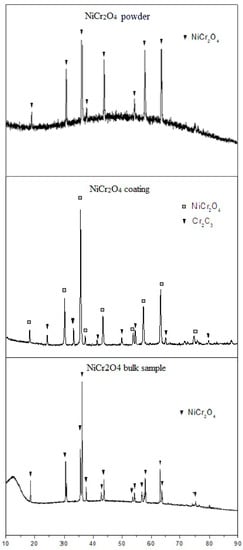
Figure 1.
XRD patterns of NiCr2O4 original powder, coating, and bulk sample.
Figure 2A shows cross-sectional SEM micrographs of APS NiCr2O4 coating interacted with CMAS. It shows that the CMAS deposit on the surface of the NiCr2O4 coating is fully melted under the heat treatment of 1200 °C for 24 h. Figure 2B shows that the microstructure, including the pores and lamellar structure of the NiCr2O4 coating, remained after CMAS interaction. There was no penetration of molten CMAS found at the border. Molten CMAS seems to be non-wetting with the NiCr2O4 coating, because the wetting angles of residue CMAS are obtuse angles and many spherical CMAS residues could be found on the surface of the NiCr2O4 coating. Figure 2B depicts an SEM image of the cross-section of the NiCr2O4 coating interacted with 35 mg/cm2 CMAS. Figure 2C−F are the EDS elemental maps of Si, Ca, Cr, and Ni in Figure 2B. It can be seen in the elemental maps that the interface between CMAS and NiCr2O4 is clear, and no elemental transportation gradient was observed from the border to each side. EDS cation compositions (at %) of the upper square (residue CMAS) and lower square (edge of the NiCr2O4 coating) in Figure 2B are listed in Table 2. The atomic ratio of Ni/Cr in the NiCr2O4 coating was 0.36 and the theoretical atomic ratio was 0.5. The atomic ratio of Ca/Si in residue CMAS on the surface was also similar to the composition of the simulated CMAS glass frit. The element distributions of both NiCr2O4 and CMAS after the heat treatment are similar to their original states.
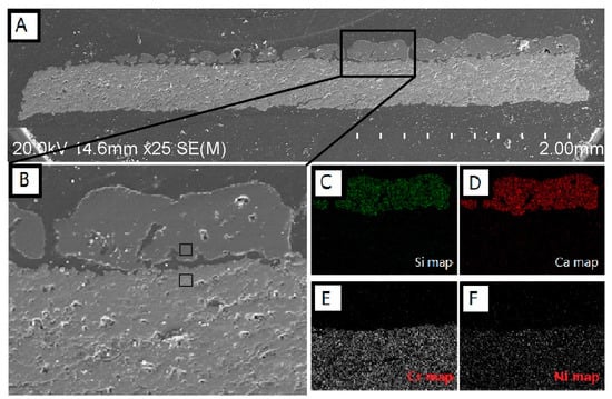
Figure 2.
(A) Cross-sectional SEM micrographs of APS NiCr2O4 coating that interacted with 35 mg/cm2 CMAS at 1200 °C for 24 h; (B) Higher magnification image of CMAS-NiCr2O4 boundary and its (C) Si; (D) Ca; (E) Cr and (F) Ni maps.
Table 2.
EDS cation compositions (at %) of upper square (residue CMAS) and lower square (edge of NiCr2O4 coating) in Figure 2B.
Figure 3A is a high magnification SEM image of the border of interaction between residue CMAS and NiCr2O4 coating. The upper area is CMAS and the lower area shows the structure of the NiCr2O4 coating. At the contacted part of the border shown in Figure 3A,B, a split line with a width of less than 1 μm can be seen. The micro pores in the NiCr2O4 coating with a size of 3–5 μm are not filled and there is no any reaction product at the border. Some NiCr2O4 particles could be found at the edge of the residue CMAS, but no dissolving phenomenon of these particles was detected.
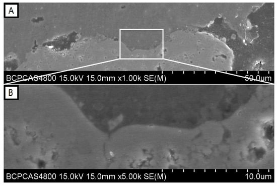
Figure 3.
(A) Contact area of the CMAS-NiCr2O4 boundary and (B) its high magnification image.
Figure 4A,B are cross-sectional SEM micrographs (low and high magnification) of NiCr2O4 bulk sample that were heat-treated with 35 mg/cm2 CMAS coating. The NiCr2O4 bulk sample has a high porosity and the pores were filled with epoxy during the SEM sample preparation. The CMAS did not infiltrate the bulk sample, but just melted and spread on the surface. The distance is less than 2 μm between letters A and B indicated in the figure, areas for which Raman spectroscopy was conducted. Figure 4C,D show the Raman spectra of CMAS and NiCr2O4 bulk samples that were marked A and B in Figure 4B. The compared standard materials of CMAS and NiCr2O4 are original powders that were heat-treated under the same conditions of 1200 °C for 24 h. The results show that the Raman spectra of the CMAS in the contact sample (area A) have similar peaks compared to the standard CMAS, and the Raman spectra of NiCr2O4 bulk samples (area B) are similar to the standard NiCr2O4. However, the peaks of the Raman spectra for CMAS and NiCr2O4 are completely different.
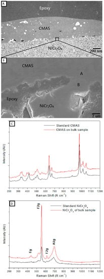
Figure 4.
(A) Cross-sectional SEM micrographs of the NiCr2O4 bulk sample that interacted with 35 mg/cm2 CMAS at 1200 °C for 24 h and (B) a high magnification image of the CMAS-NiCr2O4 boundary; (C) Raman spectra at the area marked A in (B) compared with standard CMAS and (D) at the area marked B in (B) compared with standard NiCr2O4.
It was found that both the bulk sample and free-standing coating of NiCr2O4 were non-wetting with CMAS under 1200 °C. Because the morphologies of the coating samples and bulk samples are quite different and the results of CMAS contacting experiments for both the coating sample and bulk sample are similar, it can be inferred that morphology has less influence on the CMAS barrier ability for NiCr2O4 material when the CMAS has a non-wetting surface.
The XRD result of NiCr2O4 coating shows that Cr2O3 was found in the coatings, mainly because of the melting and recrystallization during the APS procedure. It is obvious that the residue Cr2O3 does not affect the arresting ability of the coating, probably because the optical basicity of Cr2O3 (Δ∧: 0.70) is similar to that of NiCr2O4, so we can assume that it has a reacting ability with CMAS similar to NiCr2O4.
For remove of the influence of Cr2O3 impurities, NiCr2O4 bulk samples were fabricated by solid sintering and used to react with CMAS coating under the same conditions. The Raman spectra of CMAS and NiCr2O4 bulk samples were compared with a standard material, as shown in Figure 4, which gives us a new way to identify the phase structure and materials found at the micro-scale, such as at the border between CMAS and NiCr2O4 bulk samples. The NiCr2O4 bulk sample exhibited a tetragonal structure belonging to the space group I41/amd. The factor group analysis predicted the following modes in NiCr2O4:
2A1g(R) + B2g(R) + 3B1g(R) + 4Eg(R) + A2g + 2B1u + 2A1u + 4B2u + 6E2u(IR) + 4A2u(IR) + B1u [19].
There are 10 Raman active modes (2A1g + B2g + 3B1g + 4Eg) for the tetragonal structure of NiCr2O4, and some were detected in both area B in Figure 3B and in the the standard NiCr2O4 material. In contrast, the Raman spectra of area A in Figure 4B and of the pure CMAS conducted under the same heat treatment without any reaction showed high consistency, as the crystallization of CMAS occurred without any Raman active modes of NiCr2O4 in it. These results indicate that NiCr2O4 has no reaction with the CMAS bulk sample under 1200 °C, and the material transportation at border of the two materials is negligible (less than 2 μm).
Figure 5A shows a bright-field TEM image of 50%CMAS-50%NiCr2O4 powder interacted under 1200 °C for 24 h. The grain marked A was identified as NiCr2O4 using SAEDP with a best match with PDF (Powder Diffraction File) No. 23-0423 for ideal composition in the space group of I41/amd. The grain marked B was identified as a glass structure of CMAS as its SAEDP showed a typical circle pattern for amorphous glass that contains several crystals separated out from CMAS. The elemental composition for both A and B area were detected by EDS, and the results are listed in Table 3.
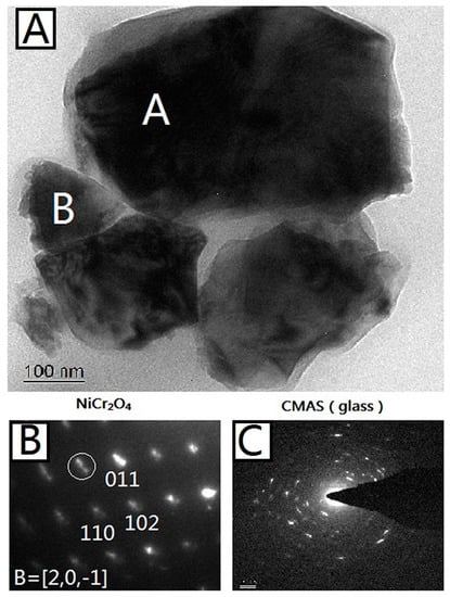
Figure 5.
(A) Bright-field TEM micrograph of 50%CMAS-50%NiCr2O4 powder interacted under 1200 °C for 24 h. Phase-identified NiCr2O4 and CMAS (glass) grains are marked; (B) Indexed SAEDP of NiCr2O4 marked with A in (A); (C) Indexed SAEDP of CMAS marked with B in (A).
Table 3.
EDS cation compositions (at %) of NiCr2O4 (area A) and CMAS (area B) in Figure 5A.
From the results, it can be seen that the interface between the two nano-sized granules marked A and B is clear and the SAEDPs show that granule A is complete NiCr2O4 crystal and granule B is an amorphous structure of CMAS. The element composition dictated by EDS, as shown in Table 3, also proves that result, because the granule A is composed of 99% Ni, Cr, and O, and granule B is composed of 99% Ca, Mg, Al, Si, and O. This indicates that the chemical stability between NiCr2O4 and CMAS is relative high for such a strong contact (nano-size) and long interacting period (24 h).
The previous results show that NiCr2O4 ceramic has good chemical stability with molten CMAS, so they do not react under 1200 °C for a relatively long time (24 h). Chemical stability and non-wetting ability are the dominant factors that enable NiCr2O4 to work as an anti-CMAS material. The advantage of this kind of material is that it does not permit the formation of a reacting zone, thus arresting CMAS penetration and reducing the stress in the coating system. Furthermore, the thermal barrier ability of the coating can be maintained after CMAS attack, as it maintains a porous structure.
4. Conclusions
The results show that three different types of NiCr2O4 material reveal many details on this issue. The reaction of nano-sized CMAS-NiCr2O4 mixed powder shows that NiCr2O4 has outstanding chemical stability with molten CMAS under 1200 °C, as predicted by the optical basicity analysis. No reaction was detected for a relatively long time (24 h). The morphology difference between the coating and bulk sample does not affect the chemical stability between CMAS and NiCr2O4. Also, the impurity of Cr2O3 (about 18.4%, according to intensity of peaks) was detected in the coating sample, indicating that a small amount of Cr2O3 in NiCr2O4 does not influence the chemical stability of NiCr2O4 with CMAS. Finally, both of the CMAS-contacting experiments the for coating and bulk sample show that NiCr2O4 and molten CMAS are non-wetting at 1200 °C, and there is not any element transportation across the border between them. The results indicate that NiCr2O4 can be used as a potential impermeable anti-CMAS material for the protection of TBCs. The methods of optical basicity and the analysis of CMAS-TBC reacting products could also be used in the search for other impermeable materials.
Acknowledgments
This work was financially supported by the National Natural Science Foundation of China (No. 51772027).
Author Contributions
Zhuang Ma and Xing Li conceived and designed the experiments; Xing Li and Yanbo Liu performed the experiments; Xing Li and Ling Liu analyzed the data; Xing Li wrote the paper.
Conflicts of Interest
The authors declare no conflict of interest.
References
- Padture, N.P.; Gell, M. Thermal barrier coatings for gas-turbine engine applications. Science 2002, 296, 280–284. [Google Scholar] [CrossRef] [PubMed]
- Clarke, D.R. Materials selection guidelines for low thermal conductivity thermal barrier coatings. Surf. Coat. Technol. 2003, 163–164, 67–74. [Google Scholar] [CrossRef]
- Clarke, D.R.; Levi, C.G. Materials design for the next generation thermal barrier coatings. Annu. Rev. Mater. Res. 2003, 33, 383–417. [Google Scholar] [CrossRef]
- Zhao, H.; Levi, C.G. Molten silicate interactions with thermal barrier coatings. Surf. Coat. Technol. 2014, 251, 74–86. [Google Scholar] [CrossRef]
- Kakuda, T.R.; Levi, C.G. The thermal behavior of CMAS-infiltrated thermal barrier coatings. Surf. Coat. Technol. 2015, 272, 350–356. [Google Scholar] [CrossRef]
- Krause, A.R.; Li, X.; Padture, N.P. Interaction between ceramic powder and molten calcia-magnesia-alumino-silicate (CMAS) glass, and its implication on CMAS-resistant thermal barrier coatings. Scr. Mater. 2016, 112, 118–122. [Google Scholar] [CrossRef]
- Garces, H.F.; Senturk, B.S.; Padture, N.P. In situ Raman spectroscopy studies of high-temperature degradation of thermal barrier coatings by molten silicate deposits. Scr. Mater. 2014, 76, 29–32. [Google Scholar] [CrossRef]
- Vidal-Setif, M.H.; Chellah, N.; Rio, C.; Sanchez, C.; Lavigne, O. Lavigne, Calcium–magnesium–alumino–silicate (CMAS) degradation of EB-PVD thermal barrier coatings: Characterization of CMAS damage on ex-service high pressure blade TBCs. Surf. Coat. Technol. 2012, 208, 39–45. [Google Scholar] [CrossRef]
- Hasz, W.C.; Johnson, C.A.; Borom, M.P. Protection of Thermal Barrier Coating by a Sacrificial Surface Coating. U.S. Patent 5,660,885, 26 August 1997. [Google Scholar]
- Hasz, W.C.; Johnson, C.A.; Borom, M.P. Protection of Thermal Barrier Coating with an Impermeable Barrier Coating. U.S. Patent 5,871,820, 16 February 1999. [Google Scholar]
- Hasz, W.C.; Johnson, C.A.; Borom, M.P. Protected Thermal Barrier Coating Composite with Multiple Coatings. U.S. Patent 5,914,189, 22 June 1999. [Google Scholar]
- Rai, A.K.; Bhattacharya, R.S. CMAS-resistant thermal barrier coatings (TBC). Int. J. Appl. Ceram. Technol. 2010, 7, 662–674. [Google Scholar] [CrossRef]
- Wang, L.; Guo, L.; Li, Z.; Peng, H.; Ma, Y.; Gong, S.; Guo, H. Protectiveness of Pt and Gd2Zr2O7 layers on EB-PVDYSZ thermal barrier coatings against calcium–magnesium–alumina–silicate (CMAS) attack. Ceram. Int. 2015, 41, 11662–11669. [Google Scholar] [CrossRef]
- Ramachandran, C.S.; Balasubramanian, V.; Ananthapadmanabhan, P.V. Thermal cycling behaviour of plasma sprayed lanthanum zirconate based coatings under concurrent infiltration by a molten glass concoction. Ceram. Int. 2013, 39, 1413–1431. [Google Scholar]
- Levi, C.G.; Hutchinson, J.W.; Vidal-Setif, M.H.; Johnson, C.A. Environmental degradation of thermal barrier coatings by molten deposits. MRS Bull. 2012, 37, 932–941. [Google Scholar] [CrossRef]
- Drexler, J.M.; Ortiz, A.L.; Padture, N.P. Composition effects of thermal barrier coating ceramics on their interaction with molten Ca–Mg–Al–Silicate (CMAS) glass. Acta Mater. 2012, 60, 5437–5447. [Google Scholar] [CrossRef]
- Duffy, J.A.; Ingram, M.D.; Non-Crysr, J. An interpretation of glass chemistry in terms of the optical basicity concept. Solids 1976, 21, 373–410. [Google Scholar] [CrossRef]
- Dimitrov, V.; Sakka, S. Electronic oxide polarizability and optical basicity of simples oxides. J. Appl. Phys. 1996, 79, 1736–1740. [Google Scholar] [CrossRef]
- Ptak, M.; Maczka, M. Temperature-dependent XRD, IR, magnetic, SEM and TEM studies of Jahn–Teller distorted NiCr2O4 powders. J. Solid State Chem. 2013, 201, 270–279. [Google Scholar] [CrossRef]
© 2017 by the authors. Licensee MDPI, Basel, Switzerland. This article is an open access article distributed under the terms and conditions of the Creative Commons Attribution (CC BY) license (http://creativecommons.org/licenses/by/4.0/).