
A Novel Method for Borehole Blockage Removal and Experimental Study on a Hydraulic Self-Propelled Nozzle in Underground Coal Mines


Abstract
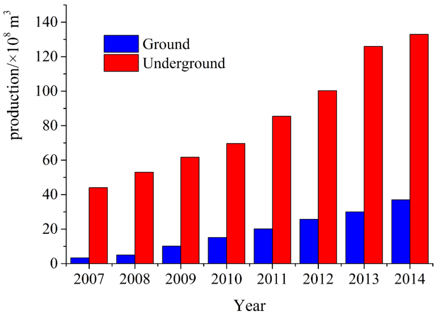
:1. Introduction
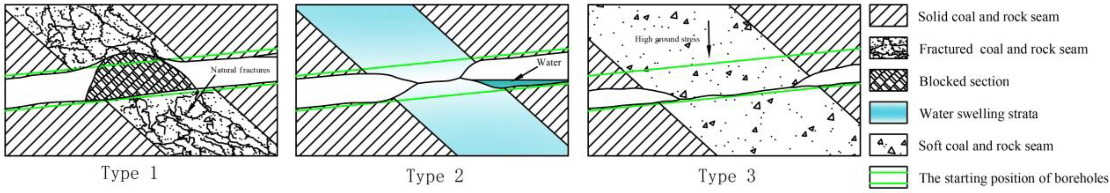
2. Analysis of Borehole Collapse
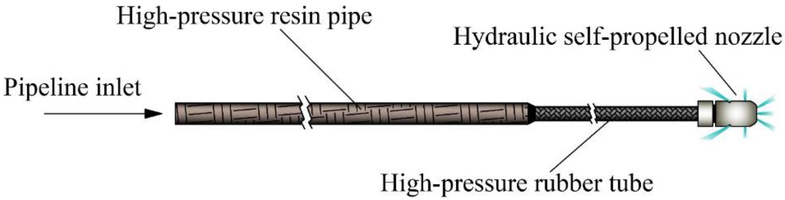
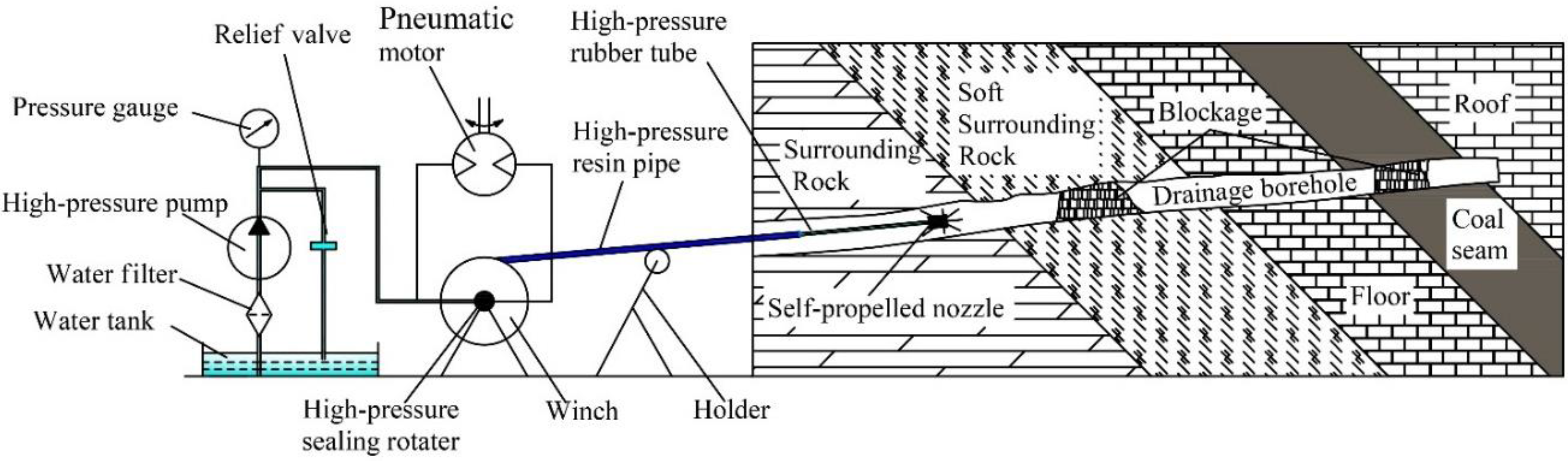
3. Method for Removing CBM Drainage Hole Blockage
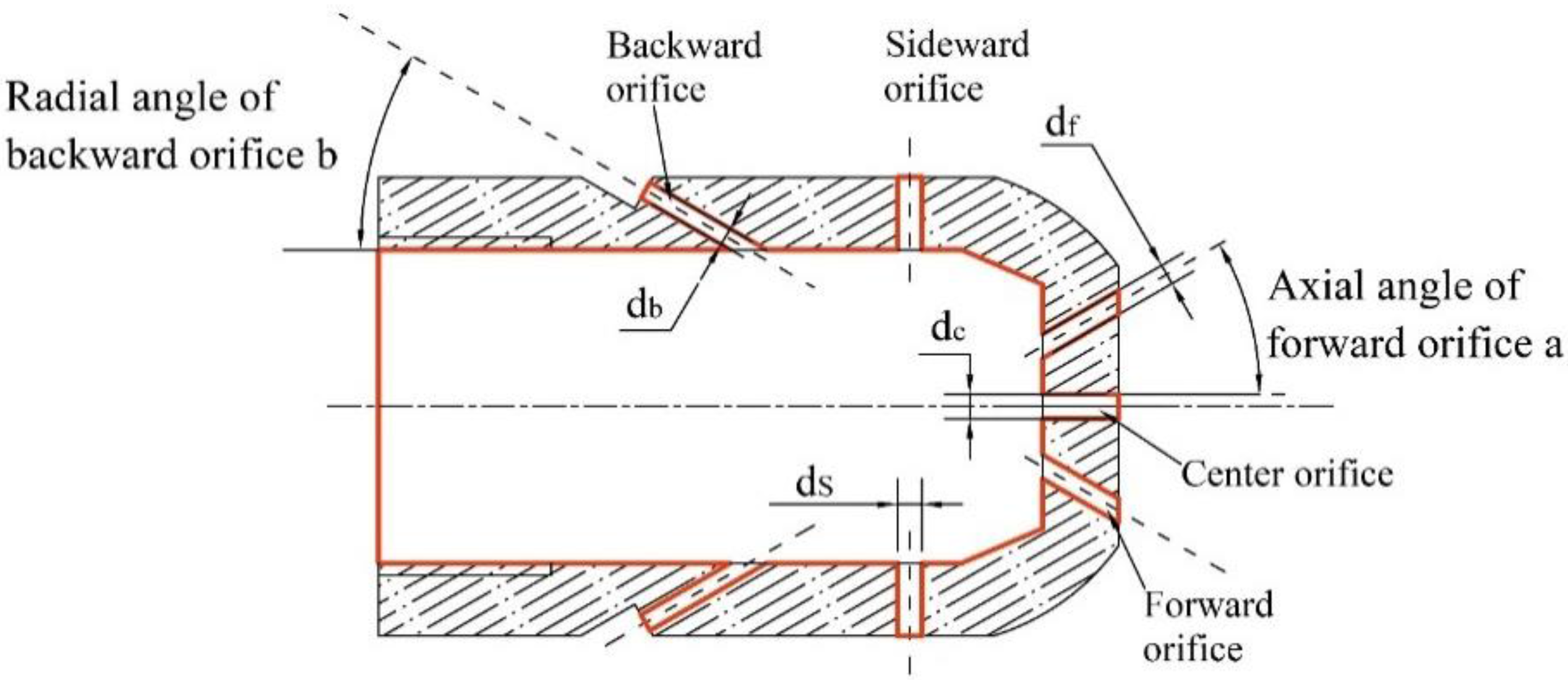
4. Experimental Study and Parameter Optimization
4.1. Optimization of Nozzle Inlet Pressure
4.2. High-Pressure Resin Pipe Selection
5. Field Experiment
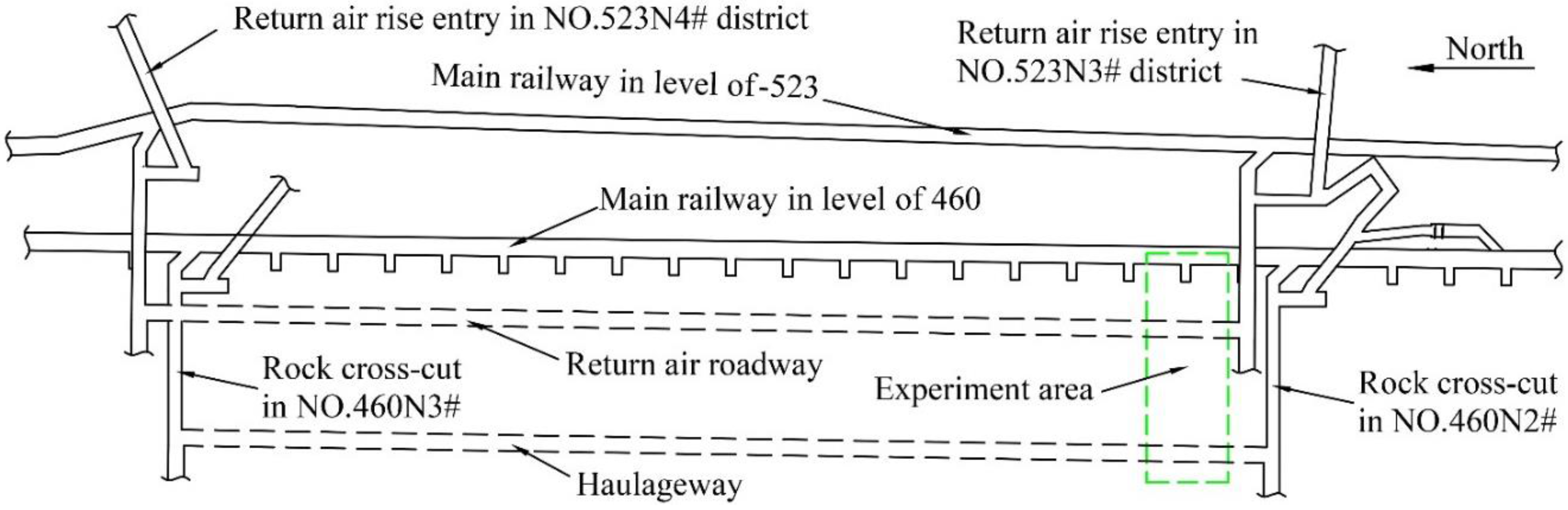
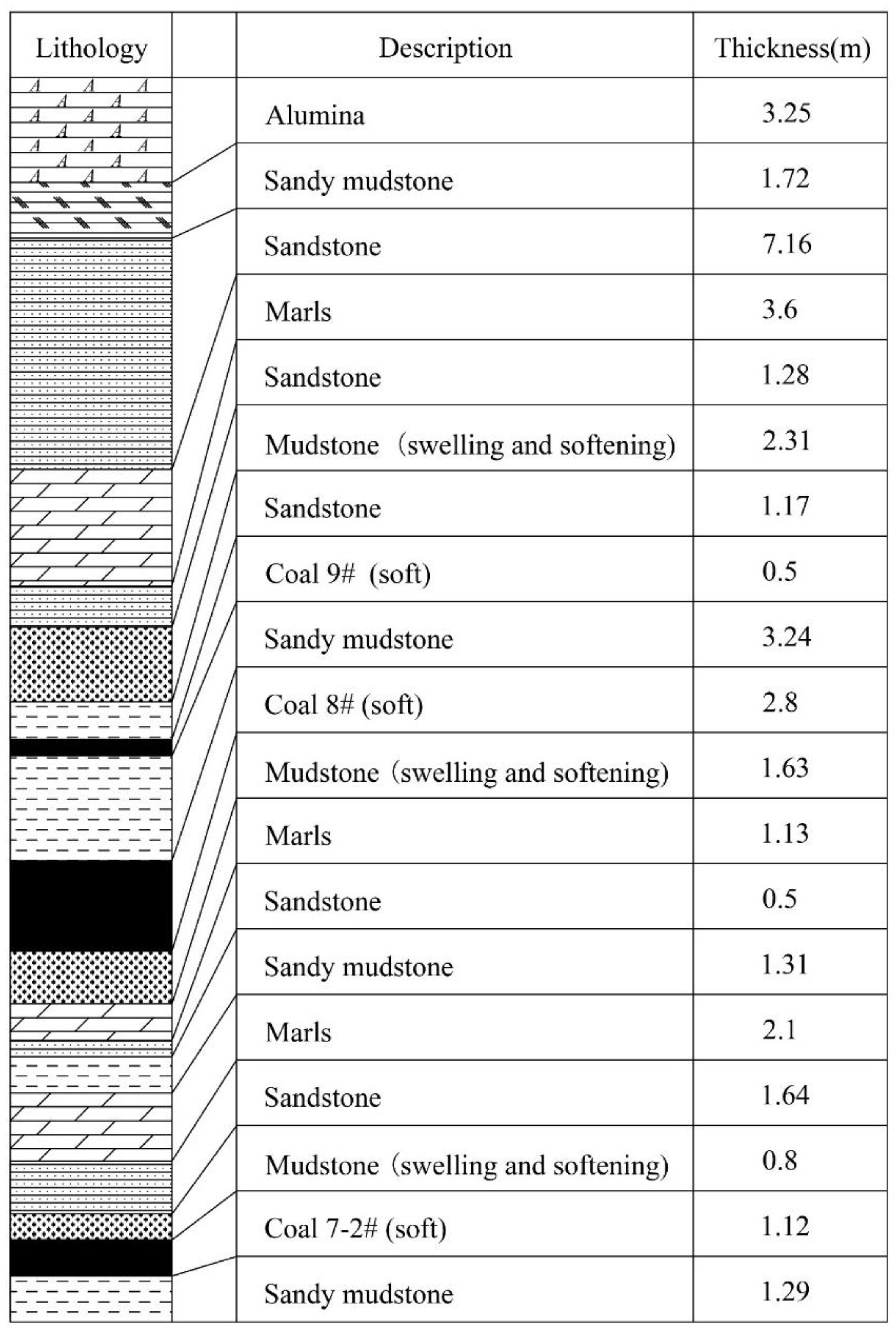
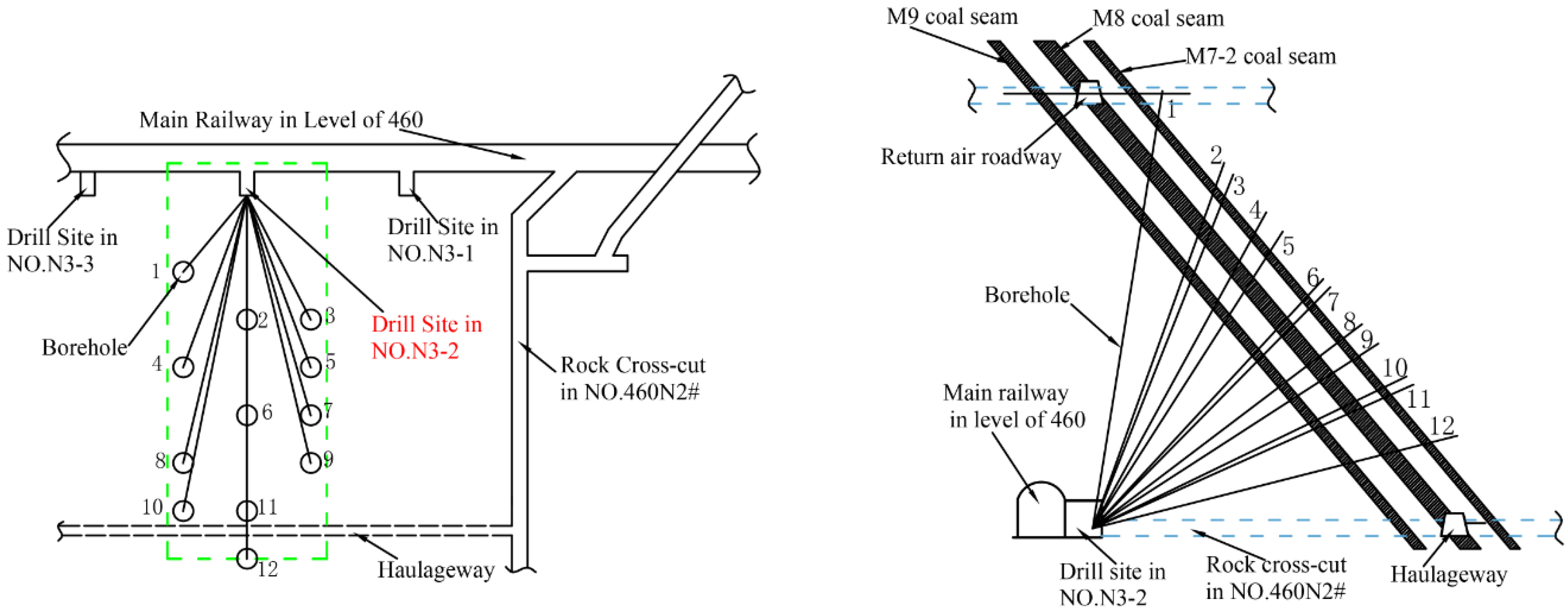
5.1. Field Experiment Site and Geological Conditions
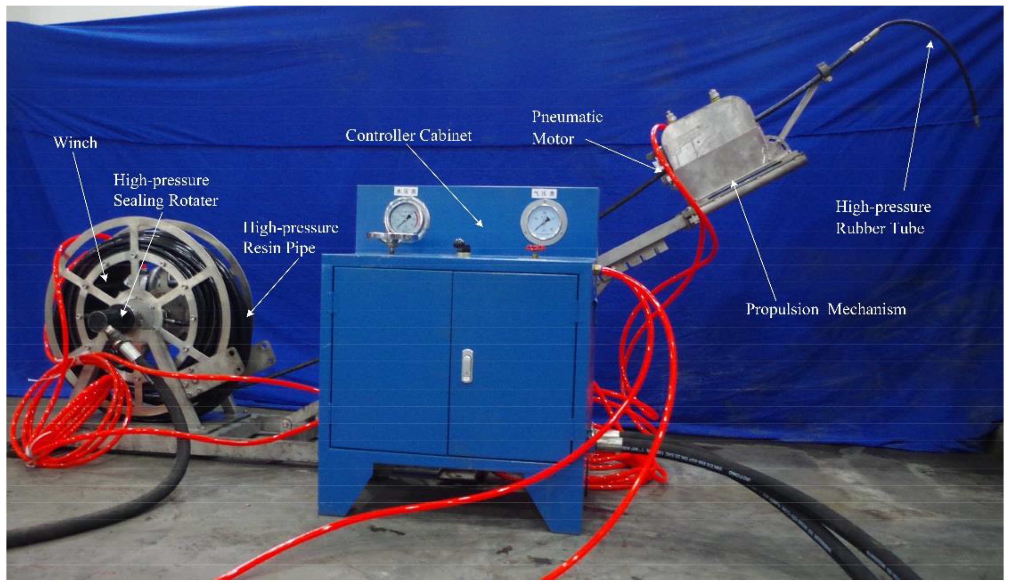
5.2. Testing Equipment
5.3. Experimental Design and Drilling Parameters
5.4. Analysis of Experimental Results
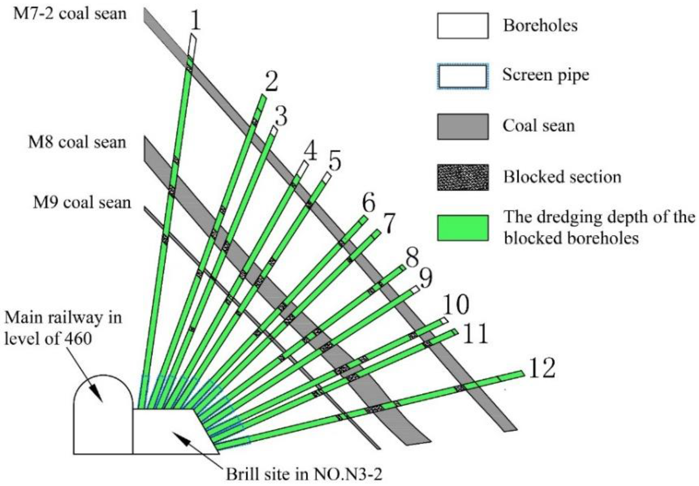
5.4.1. Analysis of Drilling and Blockage Location in the Borehole
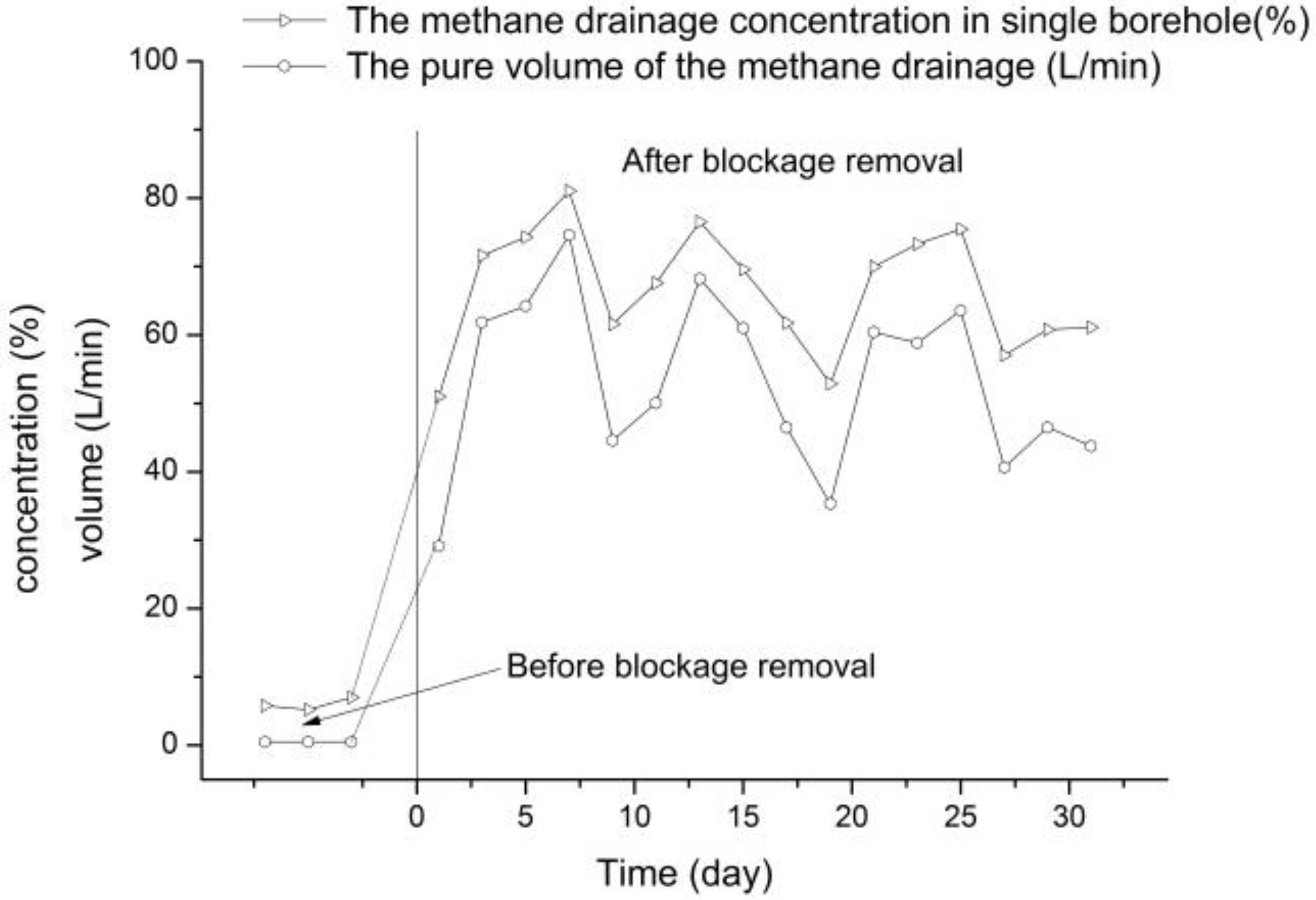
5.4.2. CBM Drainage Effect
6. Conclusions
Acknowledgments
Author Contributions
Conflicts of Interest
References
- Bibler, C.J.; Marshall, J.S.; Pilcher, R.C. Status of worldwide coal mine methane emissions and use. Int. J. Coal Geol. 1998, 35, 283–310. [Google Scholar] [CrossRef]
- Karacan, C.Ö.; Ruiz, F.A.; Cotè, M.; Phipps, S. Coal mine methane: A review of capture and utilization practices with benefits to mining safety and to greenhouse gas reduction. Int. J. Coal Geol. 2011, 86, 121–156. [Google Scholar] [CrossRef]
- Cheng, Y.P.; Wang, L.; Zhang, X.L. Environmental impact of coal mine methane emissions and responding strategies in China. Int. J. Greenh. Gas Control 2011, 5, 157–166. [Google Scholar] [CrossRef]
- Wang, F.; Ren, T.; Tu, S.; Hungerford, F.; Aziz, N. Implementation of underground longhole directional drilling technology for greenhouse gas mitigation in Chinese coal mines. Int. J. Greenh. Gas Control 2012, 11, 290–303. [Google Scholar] [CrossRef]
- Lu, T.; Yu, H.; Zhou, T.; Mao, J.; Guo, B. Improvement of methane drainage in high gassy coal seam using water jet technique. Int. J. Coal Geol. 2009, 79, 40–48. [Google Scholar] [CrossRef]
- Gao, Y.; Lin, B.; Yang, W.; Li, Z.; Pang, Y.; Li, H. Drilling large diameter cross-measure boreholes to improve gas drainage in highly gassy soft coal seams. J. Nat. Gas Sci. Eng. 2015, 26, 193–204. [Google Scholar] [CrossRef]
- Terzaghi, K. Theory of Consolidation, in Theoretical Soil Mechanics; John Wiley & Sons, Inc.: Hoboken, NJ, USA, 1943. [Google Scholar]
- Hudson, J.A.; Harrison, J.P. Engineering Rock Mechanics—An Introduction to the Principles; Elsevier: Amsterdam, The Netherlands, 2000. [Google Scholar]
- Zheng, Z.; Kemeny, J.; Cook, N.G.W. Analysis of borehole breakouts. J. Geophys. Res. Solid Earth 1989, 94, 7171–7182. [Google Scholar] [CrossRef]
- Qu, P.; Shen, R.; Fu, L.; Wang, Z. Time delay effect due to pore pressure changes and existence of cleats on borehole stability in coal seam. Int. J. Coal Geol. 2011, 85, 212–218. [Google Scholar] [CrossRef]
- Tian, L.; Cao, Y.; Chai, X.; Liu, T.; Feng, P.; Feng, H.; Zhou, D.; Shi, B.; Oestreich, R.; Rodvelt, G. Best practices for the determination of low-pressure/permeability coalbed methane reservoirs, Yuwu Coal Mine, Luan mining area, China. Fuel 2015, 160, 100–107. [Google Scholar] [CrossRef]
- Zou, Q.; Lin, B.; Zheng, C.; Hao, Z.; Zhai, C.; Liu, T.; Liang, J.; Yan, F.; Yang, W.; Zhu, C. Novel integrated techniques of drilling–slotting–separation-sealing for enhanced coal bed methane recovery in underground coal mines. J. Nat. Gas Sci. Eng. 2015, 26, 960–973. [Google Scholar] [CrossRef]
- Lu, Y.; Yang, F.; Ge, Z.; Wang, S.; Wang, Q. The influence of viscoelastic surfactant fracturing fluids on gas desorption in soft seams. J. Nat. Gas Sci. Eng. 2015, 27, 1649–1656. [Google Scholar] [CrossRef]
- Summers, D.A.; Henry, R.L. Water jet cutting of sedimentary rock. J. Pet. Technol. 1972, 24, 797–802. [Google Scholar] [CrossRef]
- Dickinson, W.; Dickinson, R.W. Horizontal radial drilling system. In Proceedings of the SPE California Regional Meeting (SPE 13949), Bakersfield, CA, USA, 27–29 March 1985.
- Dickinson, W.; Anderson, R.R.; Dickinson, R.W. The ultra-short-radius radial system. SPE Drill. Eng. 1989, 4, 247–254. [Google Scholar] [CrossRef]
- Stanislav, U.; Alexander, B.; Evgeny, T. Design and initial performance of pilot cyclic steam stimulations of vertical wells with radial horizontal bores in low-permeable heavy oil carbonates. In Proceedings of the SPE Russian Oil and Gas Technical Conference and Exhibition (SPE 115125), Moscow, Russia, 28–30 October 2008.
- Hou, Y.P.; Zhang, Y.L.; Zhang, M.T. Inquiry into gas mining with ultrashort radial radial system. J. Henan Polytech. Univ. 2005, 24, 46–49. [Google Scholar]
- Su, X.B.; Liu, X.; Ma, B.A.; Pei, G.; Feng, W.J. Repairing and enhancing permeability technology and equipment of gas drainage borehole. Coal Sci. Technol. 2014, 6, 58–60. [Google Scholar]
- Maurer, W.C.; Heilhecker, J.K.; Love, W.W. High-pressure drilling. J. Pet. Technol. 1973, 25, 851–859. [Google Scholar] [CrossRef]
- Chang, Z.X.; Zhao, Y.S.; Feng, Z.C.; Yang, D. Experimental studies on horizontal drilling hole by water jet in coal seam. Chin. J. Rock Mech. Eng. 2005, 24, 4740–4744. [Google Scholar]
- Wang, P.; Ni, H.; Wang, R.; Li, Z. Modulating downhole cuttings via a pulsed jet for efficient drilling-tool development and field testing. J. Nat. Gas Sci. Eng. 2015, 27, 1287–1295. [Google Scholar] [CrossRef]
- Lu, Y.; Liu, Y.; Li, X.; Kang, Y. A new method of drilling long boreholes in low permeability coal by improving its permeability. Int. J. Coal Geol. 2010, 84, 94–102. [Google Scholar] [CrossRef]
- Wang, Z.; Liang, Y.P.; Jin, H.W. Analysis of mechanics conditions for instability of outburst-preventing borehole. J. Min. Saf. Eng. 2008, 25, 444–448. [Google Scholar]
- Yao, X.R.; Cheng, G.L.; Shi, B.M. Analysis on gas extraction drilling instability and control method of pore-forming in deep surrounding-rock with weak structure. J. China Coal 2010, 12, 2073–2081. [Google Scholar]
- Zhai, C.; Li, Q.G.; Sun, C.; Ni, G.H.; Yang, W. Analysis on borehole instability and control method of pore-forming of hydraulic fracturing in soft coal seam. J. China Coal Soc. 2015, 37, 1431–1436. [Google Scholar]
- Huang, L.; Lu, Y.Y.; Xia, B.W.; Jia, Y.J.; Huang, F. Elastoplastic analysis of surrounding rock of drilling with strain softening model in deep soft rock. Rock Soil Mech. 2013, 34, 179–186. [Google Scholar]
- Daniel, I. Editor experimental studies of water jet impact on rock and rocklike materials. In Proceedings of the 3rd International Symposium on Jet Cutting Technology, Chicago, IL, USA, 11–13 May 1976; pp. 27–46.
- Hlaváč, L.; Hlaváčová, I.; Kušnerová, M.; Mádr, V. Research of waterjet interaction with submerged rock materials. In Proceedings of the 2001 WJTA American Water Jet Conference, Minneapolis, MN, USA, 18–21 August 2001; Hashish, M., Ed.; WJTA: Minneapolis, MN, USA, 2001; pp. 617–624. [Google Scholar]
- Lu, Y.; Huang, F.; Liu, X.; Ao, X. On the failure pattern of sandstone impacted by high-velocity water jet. Int. J. Impact Eng. 2015, 76, 67–74. [Google Scholar] [CrossRef]
- Yang, B.K.; Lu, Y.Y.; Yang, X.F.; Feng, M.T.; Zhang, S. Design and research of self-propelled nozzle worked in coal seam with water jet. Machinery 2011, 38, 6–17. [Google Scholar]
- Lu, Y.; Zhou, Z.; Ge, Z.L.; Zhang, X.; Li, Q. Research on and design of a self-propelled nozzle for the tree-type drilling technique in underground coal mines. Energies 2015, 8, 14260–14271. [Google Scholar] [CrossRef]
- Lu, Y.Y.; Cheng, L.; Ge, Z.L.; Xia, B.W.; Li, Q.; Chen, J. Analysis on the initial cracking parameters of cross-measure hydraulic fracture in underground coal mines. Energies 2015, 8, 6977–6994. [Google Scholar] [CrossRef]


| Properties | Value |
|---|---|
| Mean tilt angle | 55° |
| Average propensity | 292° |
| Thickness of M2-7 coal seam | 0.91 m |
| Thickness of M8 coal seam | 2.29 m |
| Thickness of M9coal seam | 0.4 m |
| Methane content | 18.09–25.87 m3/t |
| Number | Direction Angle/(°) | Elevation Angles/(°) | Length of Boreholes/(m) | Number | Direction Angle/(°) | Elevation Angles/(°) | Length of Boreholes/(m) |
|---|---|---|---|---|---|---|---|
| 1 | −72.2 | 82.5 | 66.3 | 7 | 38.2 | 45.4 | 51.2 |
| 2 | 0 | 70.2 | 52.2 | 8 | −35 | 37.1 | 50.3 |
| 3 | 58.4 | 68.3 | 58.4 | 9 | 33.8 | 32.9 | 48.3 |
| 4 | −44.3 | 61.2 | 52 | 10 | −31.2 | 25.8 | 51.8 |
| 5 | 47.3 | 57.3 | 53.1 | 11 | 0 | 24.1 | 45.9 |
| 6 | 0 | 47.2 | 44.8 | 12 | 0 | 14.2 | 48.3 |
| Number | Before Blockage Removal | After Blockage Removal | ||
|---|---|---|---|---|
| The Average Pure Volume of the Methane Drainage of a Single Borehole/(L/min) | The Methane Drainage Concentration of a Single Borehole/(%) | The Average Pure Volume of the Methane Drainage of a Single Borehole/(L/min) | The Methane Drainage Concentration of a Single Borehole/(%) | |
| 1 | ≈0.03 | <5% | 3.67 | 62 |
| 2 | ≈0.03 | <5% | 3.07 | 56 |
| 3 | ≈0.03 | <5% | 2.47 | 49 |
| 4 | ≈0.03 | <5% | 1.91 | 43 |
| 5 | ≈0.03 | <5% | 2.86 | 54 |
| 6 | ≈0.03 | <5% | 4.79 | 70 |
| 7 | ≈0.03 | <5% | 4.79 | 66 |
| 8 | ≈0.03 | <5% | 4.13 | 64 |
| 9 | ≈0.03 | <5% | 6.08 | 77 |
| 10 | ≈0.03 | <5% | 7.30 | 85 |
| 11 | ≈0.03 | <5% | 6.56 | 81 |
| 12 | ≈0.03 | <5% | 5.46 | 73 |
© 2016 by the authors; licensee MDPI, Basel, Switzerland. This article is an open access article distributed under the terms and conditions of the Creative Commons Attribution (CC-BY) license (http://creativecommons.org/licenses/by/4.0/).
Share and Cite
Ge, Z.; Deng, K.; Lu, Y.; Cheng, L.; Zuo, S.; Tian, X. A Novel Method for Borehole Blockage Removal and Experimental Study on a Hydraulic Self-Propelled Nozzle in Underground Coal Mines. Energies 2016, 9, 698. https://doi.org/10.3390/en9090698
Ge Z, Deng K, Lu Y, Cheng L, Zuo S, Tian X. A Novel Method for Borehole Blockage Removal and Experimental Study on a Hydraulic Self-Propelled Nozzle in Underground Coal Mines. Energies. 2016; 9(9):698. https://doi.org/10.3390/en9090698
Chicago/Turabian StyleGe, Zhaolong, Kai Deng, Yiyu Lu, Liang Cheng, Shaojie Zuo, and Xingdi Tian. 2016. "A Novel Method for Borehole Blockage Removal and Experimental Study on a Hydraulic Self-Propelled Nozzle in Underground Coal Mines" Energies 9, no. 9: 698. https://doi.org/10.3390/en9090698
APA StyleGe, Z., Deng, K., Lu, Y., Cheng, L., Zuo, S., & Tian, X. (2016). A Novel Method for Borehole Blockage Removal and Experimental Study on a Hydraulic Self-Propelled Nozzle in Underground Coal Mines. Energies, 9(9), 698. https://doi.org/10.3390/en9090698