
A Study of an Effective Heat-Dissipating Piezoelectric Fan for High Heat Density Devices

Abstract
:
1. Introduction
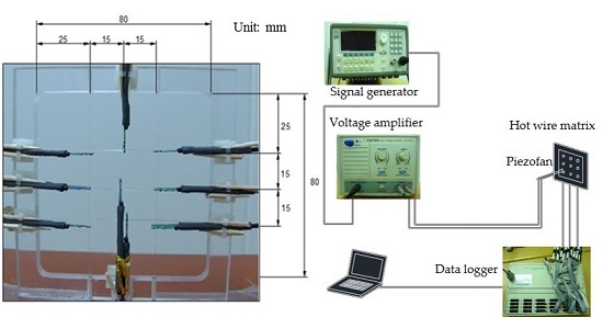
2. Experimental Procedures
3. Theoretical Analysis
3.1. Governing Equations
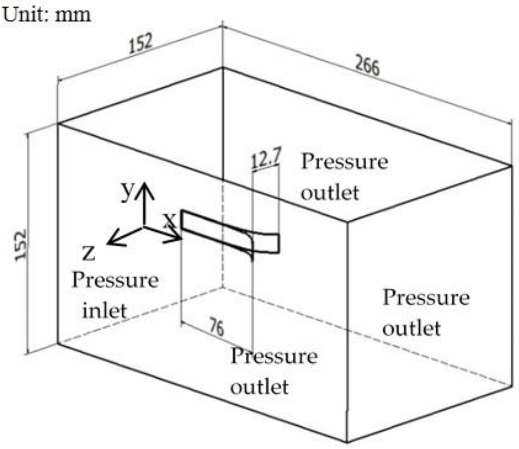
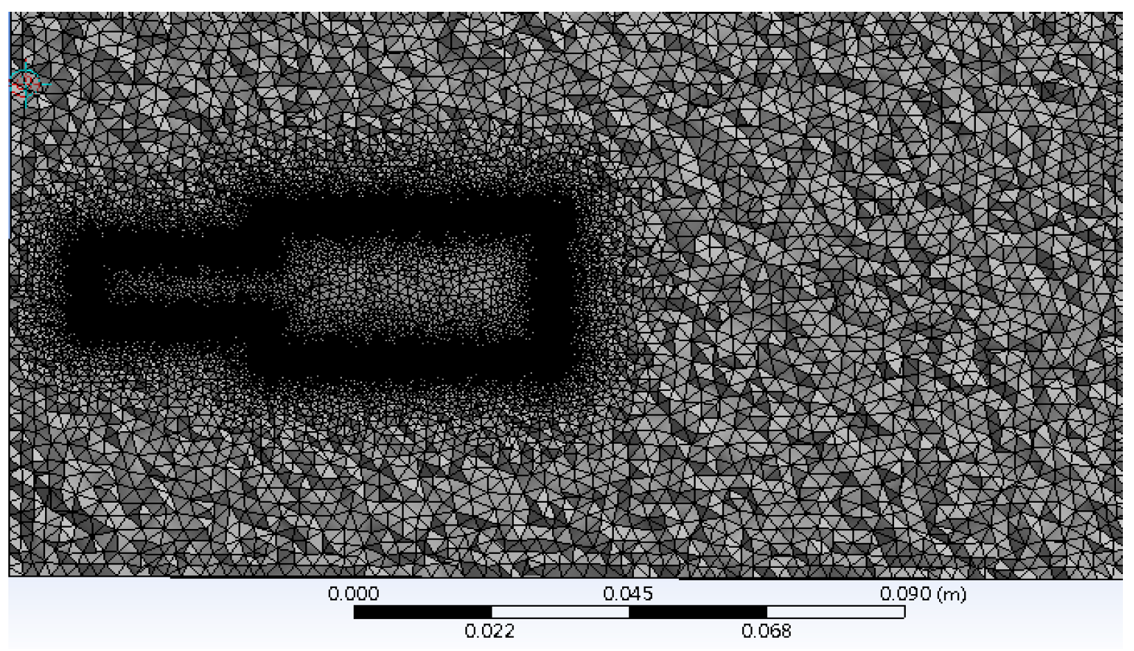
3.2. Numerical Method
4. Results and Discussion
5. Conclusions
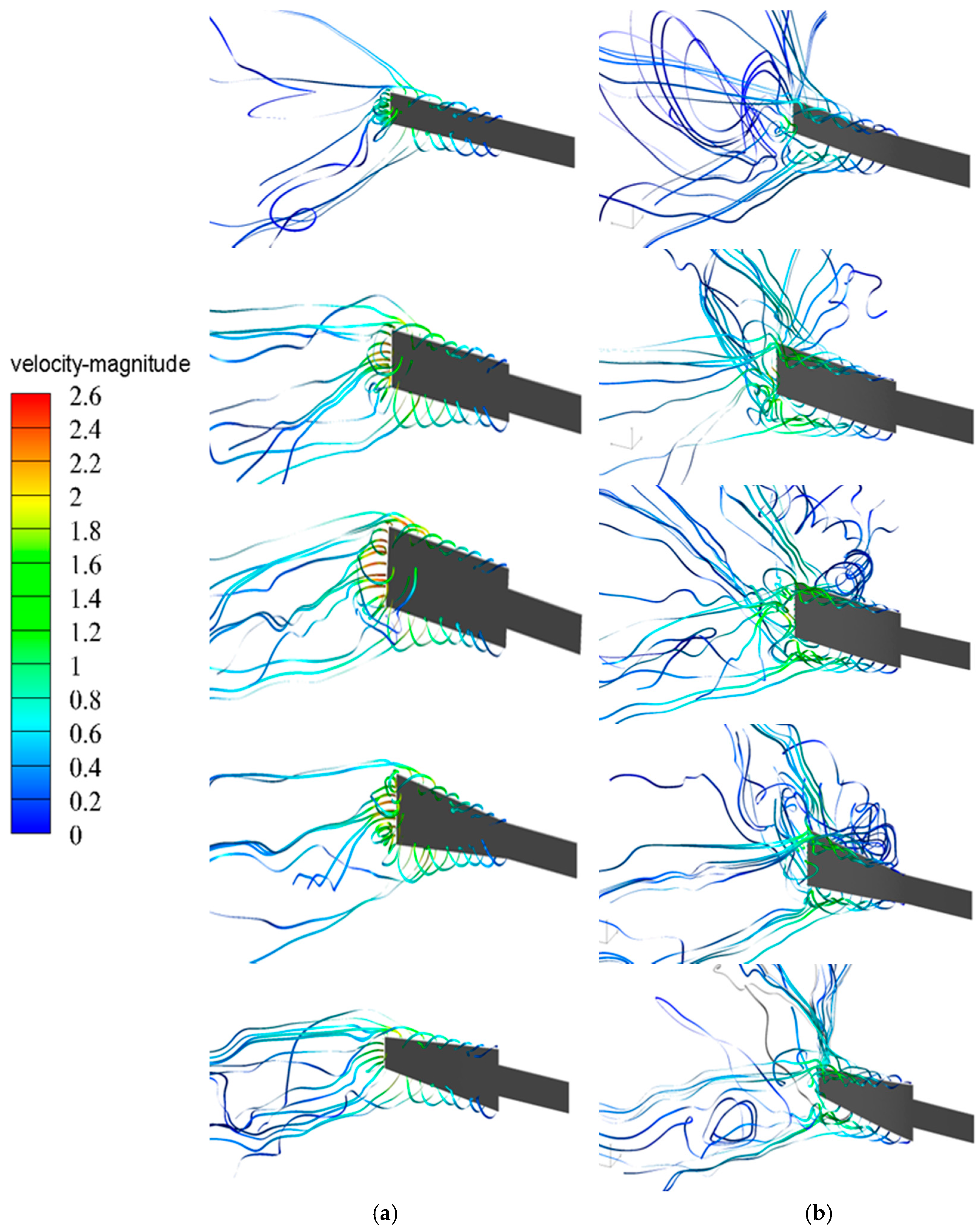
- While the vibrating blade moves toward the neutral position, most of the streamlines released from the piezofan are dragged by the moving blade and flow back to the side surface of the piezofans for Piezofans A, B, C and D. However, this phenomenon does not occur for the contracted blade shape (Piezofan E).
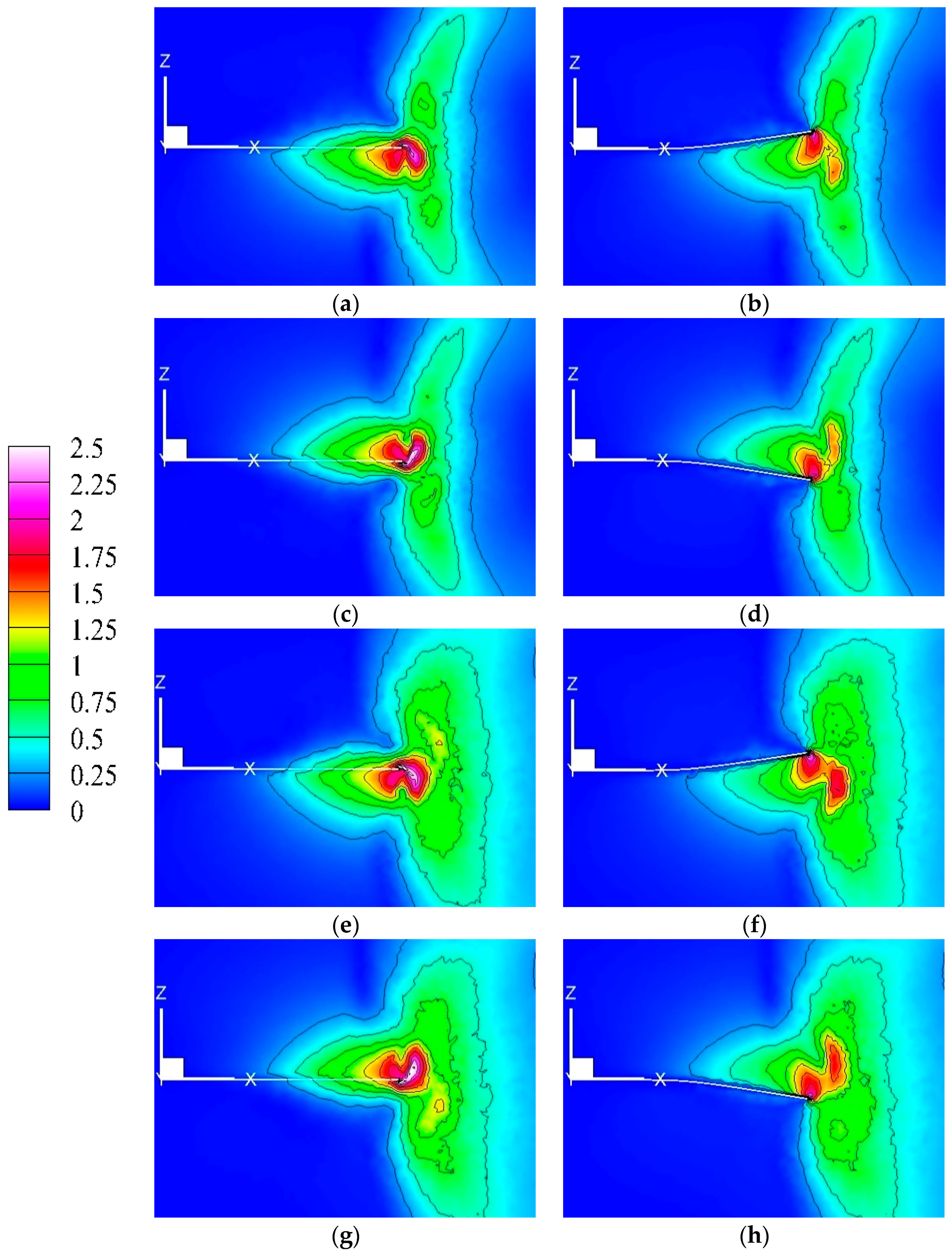
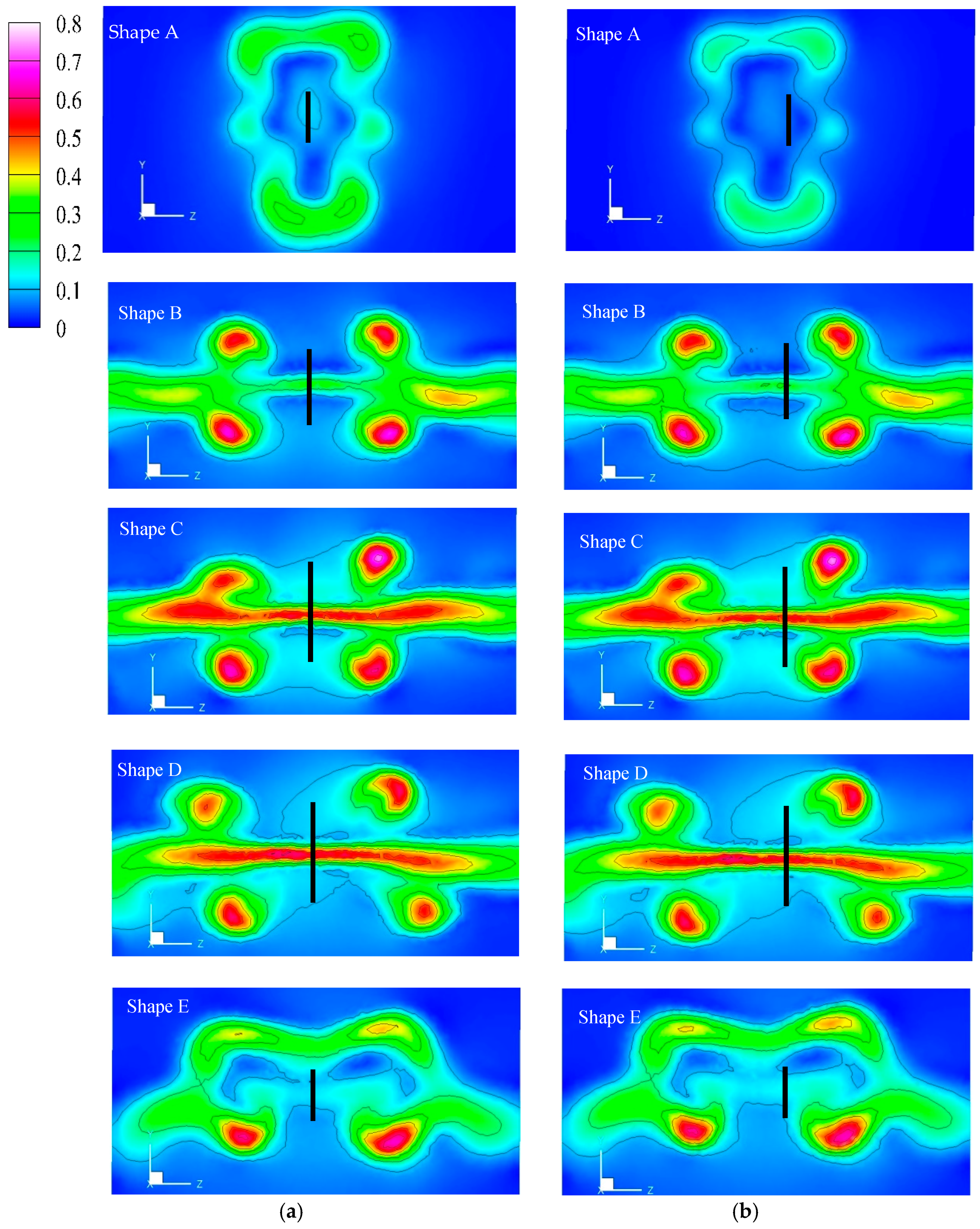
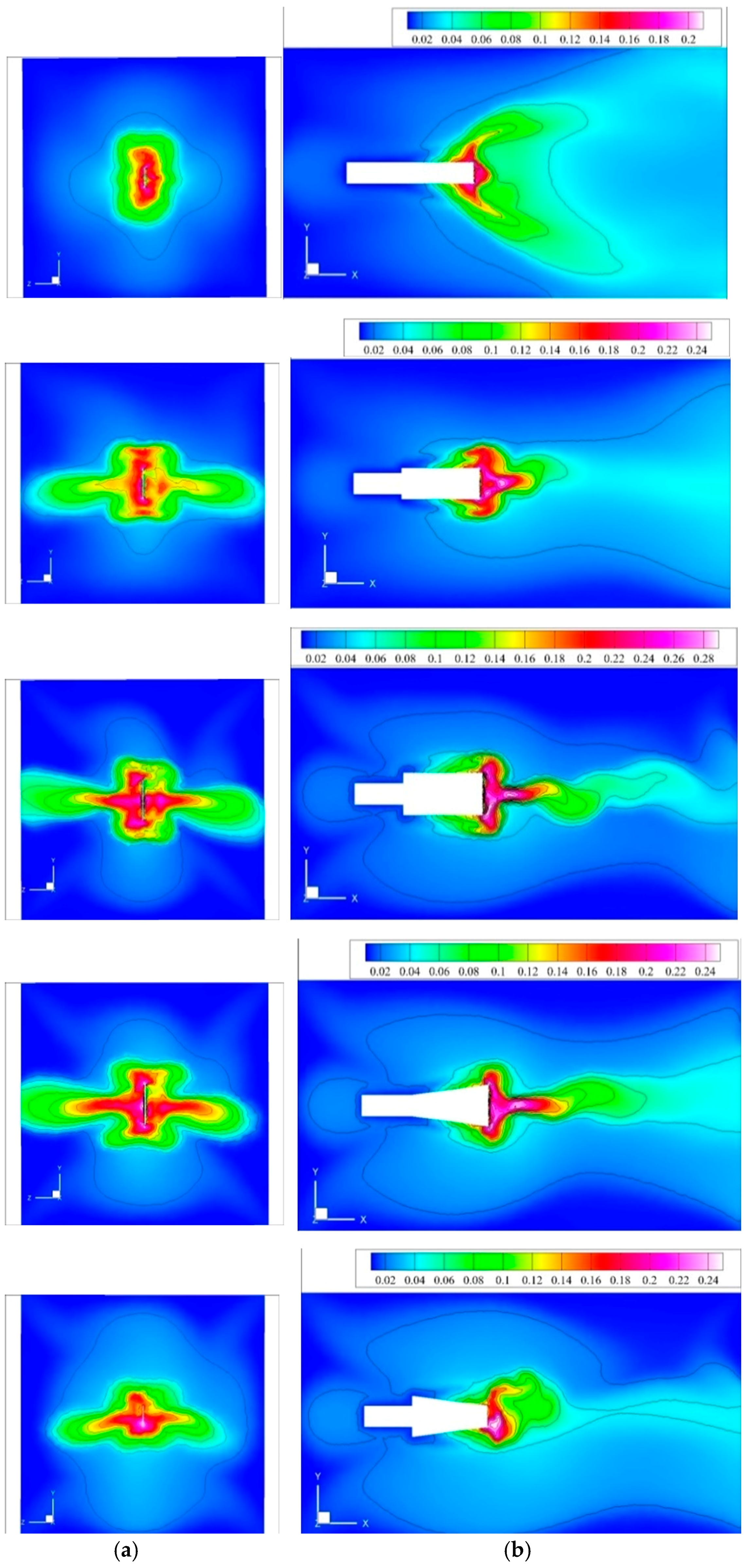
- The maximum-velocity region in front of the fan tip is due to the dragged and pushed flow by the blade. Local-maximum-velocity regions at the four corners of the central region are produced by the flow released from the blade edges.
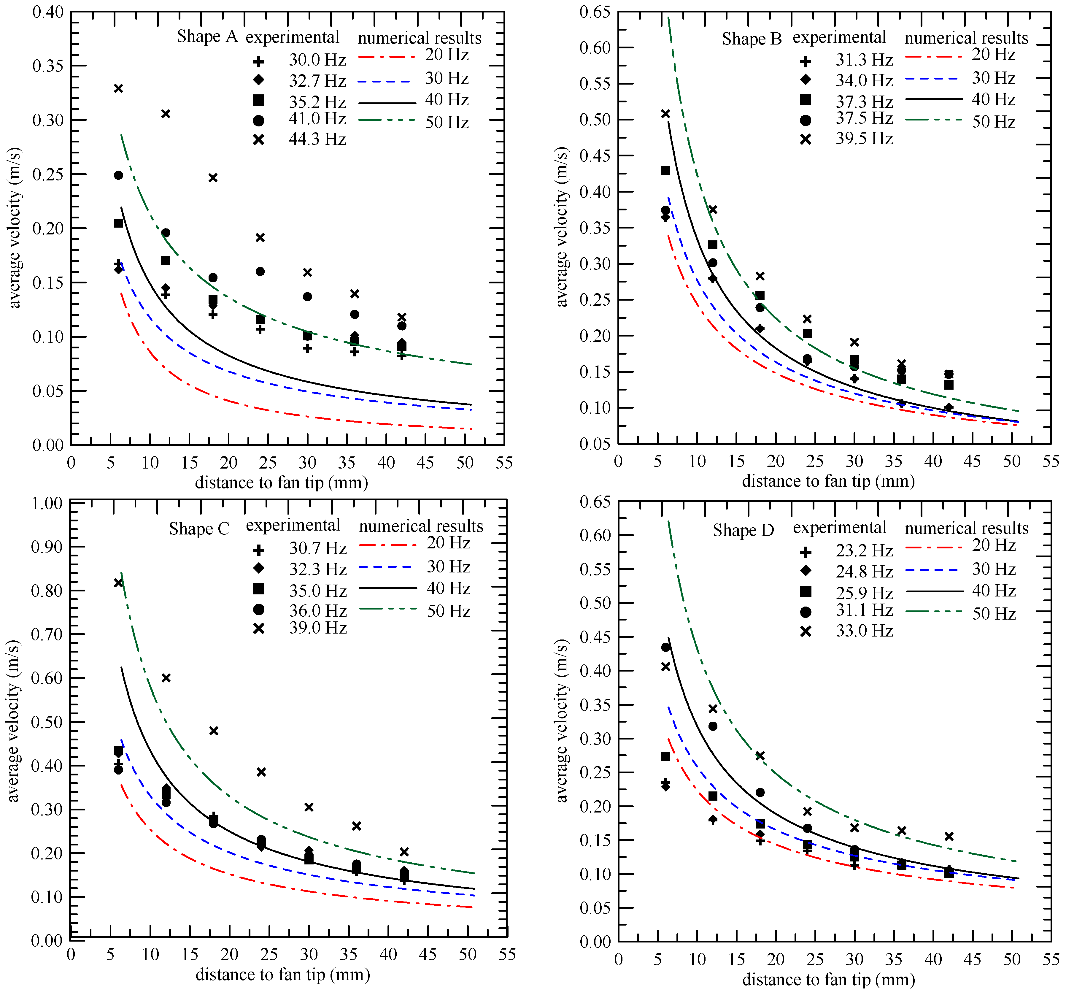
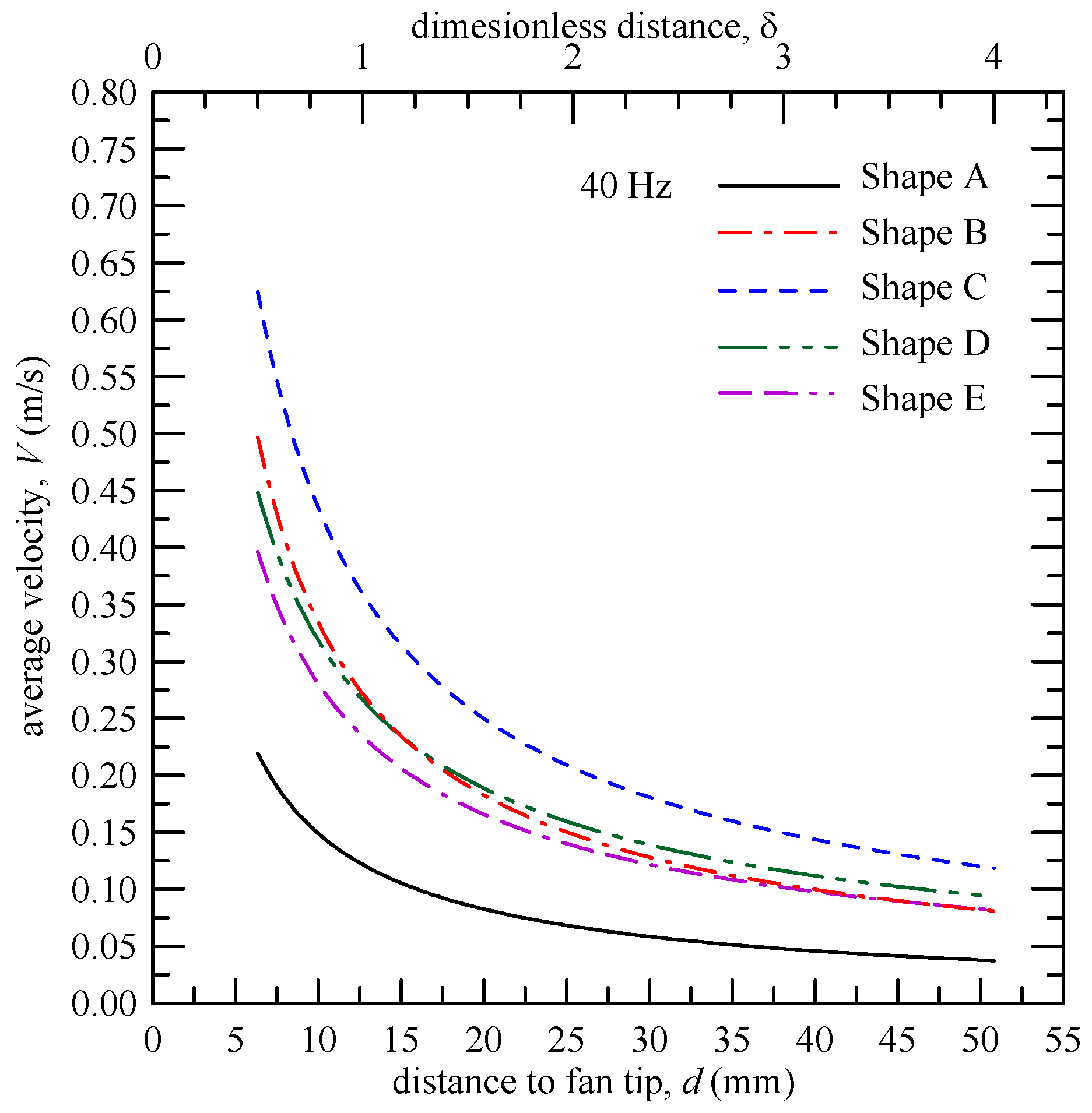
- The variation of the velocity with distance away from the tip is similar to that of a jet-like flow, but decrease more rapidly. The average velocity of the streams decays steeply within a short distance of 20 mm (δ = 1.5) from the blade tip.
- In general, a blade with a larger width has a larger velocity. The blade with a contracted shape (Piezofan E) is better for hot spot heat sources than those with divergent and rectangular shapes (Piezofans D and B).
Acknowledgments
Author Contributions
Conflicts of Interest
Nomenclature
| A | amplitude of piezofan tip, mm |
| ci | constant in Equations (3) and (4) |
| d | distance from fan tip along the axis of the piezofan, mm |
| F1,F2 | polynomials in Equations (5) and (6) |
| f | first mode resonance frequency, Hz |
| I | turbulence intensity, |
| i,j,k | coordinate indices |
| L1,L2 | length of piezofan blade, mm |
| p | pressure, Pa |
| ui | velocity component, m·s−1 |
| Vk | velocity magnitude, m·s−1 |
| average velocity magnitude, m·s−1 | |
| w | width of piezofan, mm |
| x,y,z | space coordinates |
| α | dimensionless amplitude of piezofan, |
| δ | dimensionless distance from fan tip, |
| ε | turbulent dissipation rate, m2·s−3 |
| κ | turbulent kinetic energy, m2·s−2 |
| μ | dynamic viscosity, N s·m−2 |
| density of air, kg·m−3 | |
| τ | time, s |
| vibration period of piezofan, s | |
| ϖ | turbulent frequency (specific dissipation rate), s−1 () |
References
- Toda, M. Theory of air flow generation by a resonant type PVF2 bimorph cantilever vibrator. Ferroelectrics 1979, 22, 911–918. [Google Scholar] [CrossRef]
- Toda, M. Voltage-induced large amplitude bending device PVF2 bimorph—Its properties and applications. Ferroelectrics 1981, 32, 127–133. [Google Scholar] [CrossRef]
- Açıkalın, T.; Wait, S.; Garimella, S.V.; Raman, A. Experimental investigation of the thermal performance of piezoelectric fans. Heat Transf. Eng. 2004, 25, 4–14. [Google Scholar] [CrossRef]
- Kimber, M.; Garimella, S.V.; Raman, A. Local heat transfer coefficients induced by piezoelectrically actuated vibrating cantilevers. J. Heat Transf. 2007, 129, 1168–1176. [Google Scholar] [CrossRef]
- Kimber, M.; Garimella, S.V.; Raman, A. Measurement and prediction of the cooling characteristics of a generalized vibrating piezoelectric fan. Int. J. Heat Mass Transf. 2009, 52, 4470–4478. [Google Scholar] [CrossRef]
- Liu, S.F.; Huang, R.T.; Sheu, W.J.; Wang, C.C. Heat transfer by a piezoelectric fan on a flat surface subject to the influence of horizontal/vertical arrangement. Int. J. Heat Mass Transf. 2009, 52, 2565–2570. [Google Scholar] [CrossRef]
- Ma, S.L.; Chen, J.W.; Li, H.Y.; Yang, J.T. Mechanism of enhancement of heat transfer for plate-fin heat sinks with dual piezoelectric fans. Int. J. Heat Mass Transf. 2015, 90, 454–465. [Google Scholar] [CrossRef]
- Ihara, A.; Watanabe, H. On the flow around flexible plates oscillating with large amplitude. J. Fluids Struct. 1994, 8, 601–619. [Google Scholar] [CrossRef]
- Florio, L.A.; Harnoy, A. Use of a vibrating plate to enhance natural convection cooling of a discrete heat source in a vertical channel. Appl. Therm. Eng. 2007, 27, 2276–2293. [Google Scholar] [CrossRef]
- Abdullah, M.K.; Abdullah, M.Z.; Ramana, M.V.; Khor, C.Y.; Ahmad, K.A.; Mujeebu, M.A.; Ooi, Y.; Mohd, R.Z. Numerical and experimental investigations on effect of fan height on the performance of piezoelectric fan in microelectronic cooling. Int. Commun. Heat Mass Transf. 2009, 36, 51–58. [Google Scholar] [CrossRef]
- Açıkalın, T.; Garimella, S.V. Analysis and prediction of the thermal performance of piezoelectrically actuated fans. Heat Transf. Eng. 2009, 30, 487–498. [Google Scholar] [CrossRef]
- Dey, S.; Chakrborty, D. Enhancement of convective cooling using oscillating fins. Int. Commun. Heat Mass Transf. 2009, 36, 508–512. [Google Scholar] [CrossRef]
- Choi, M.; Lee, S.Y.; Kim, Y.K. On the flow around a vibrating cantilever pair with different phase angles. Eur. J. Mech.-B/Fluids 2012, 34, 146–157. [Google Scholar] [CrossRef]
- Lin, C.N. Analysis of three-dimensional heat and fluid flow induced by piezoelectric fan. Int. J. Heat Mass Transf. 2012, 55, 3043–3053. [Google Scholar] [CrossRef]
- Lin, C.N. Heat transfer enhancement analysis of a cylindrical surface by a piezoelectric fan. Appl. Therm. Eng. 2013, 50, 693–703. [Google Scholar] [CrossRef]
- Huang, C.H.; Chen, Y.F.; Ay, H. An Inverse Problem in Determining the Optimal Position for Piezoelectric Fan. Int. J. Heat Mass Transf. 2012, 55, 5289–5301. [Google Scholar] [CrossRef]
- Yoo, J.H.; Hong, J.I.; Cao, W. Piezoelectric ceramic bimorph coupled to thin metal plate fan as cooling fan for electronic devices. Sens. Actuators A Phys. 2000, 79, 8–12. [Google Scholar] [CrossRef]
- Shyu, J.C.; Syu, J.Z. Plate-fin array cooling using a finger-like piezoelectric fan. Appl. Therm. Eng. 2014, 2, 573–580. [Google Scholar] [CrossRef]
- Lin, C.N.; Leu, J.S. Study of thermal and flow characteristics of a heated cylinder under dual piezoelectric fans actuation. Int. J. Heat Mass Transf. 2014, 78, 1008–1022. [Google Scholar] [CrossRef]
- Holman, J.P. Experimental Methods for Engineers; McGraw-Hill: Singapore, Singapore, 2001. [Google Scholar]
- Pope, S.B. Turbulent Flows; Cambridge University Press: Cambridge, UK, 2000; Chapter 10. [Google Scholar]
- Roache, P.J. Verification and Validation in Computational Science and Engineering; Hermosa Publishers: Albuquerque, NM, USA, 1998; Chapter 5. [Google Scholar]


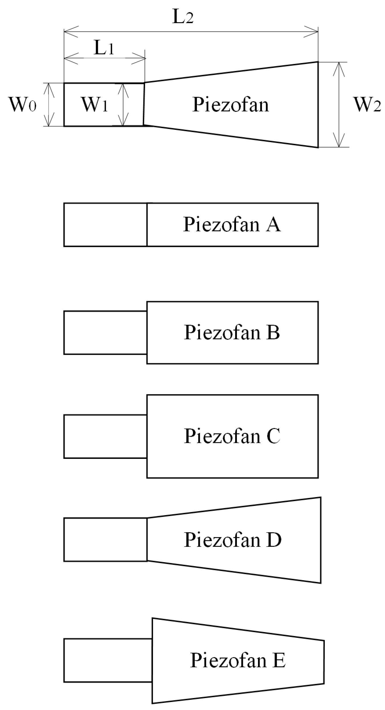
| L1 | L2 | W0 | W1 | W2 | W2/W1 | |
|---|---|---|---|---|---|---|
| Piezofan A | 29 | 76 | 12.7 | 12.7 | 12.7 | 1 |
| Piezofan B | 19.1 | 19.1 | 1 | |||
| Piezofan C | 25.4 | 25.4 | 1 | |||
| Piezofan D | 12.7 | 25.4 | 2 | |||
| Piezofan E | 25.4 | 12.7 | 0.5 |
© 2016 by the authors; licensee MDPI, Basel, Switzerland. This article is an open access article distributed under the terms and conditions of the Creative Commons Attribution (CC-BY) license (http://creativecommons.org/licenses/by/4.0/).
Share and Cite
Lin, C.-N.; Jang, J.-Y.; Leu, J.-S. A Study of an Effective Heat-Dissipating Piezoelectric Fan for High Heat Density Devices. Energies 2016, 9, 610. https://doi.org/10.3390/en9080610
Lin C-N, Jang J-Y, Leu J-S. A Study of an Effective Heat-Dissipating Piezoelectric Fan for High Heat Density Devices. Energies. 2016; 9(8):610. https://doi.org/10.3390/en9080610
Chicago/Turabian StyleLin, Chien-Nan, Jiin-Yuh Jang, and Jin-Sheng Leu. 2016. "A Study of an Effective Heat-Dissipating Piezoelectric Fan for High Heat Density Devices" Energies 9, no. 8: 610. https://doi.org/10.3390/en9080610
APA StyleLin, C.-N., Jang, J.-Y., & Leu, J.-S. (2016). A Study of an Effective Heat-Dissipating Piezoelectric Fan for High Heat Density Devices. Energies, 9(8), 610. https://doi.org/10.3390/en9080610