Abstract
The effects of using a wind acceleration device (wind lens) with vertical-axis wind turbines in wind tunnel experiments were examined. A wind lens consists of a diffuser and flanges, and this study investigated the optimum parameters of their configuration with regard to the power augmentation of the turbines. The wind lens with a flat-panel-type diffuser demonstrated power augmentation by a factor of 2.0 compared with an open wind turbine. An increase from 5° to 20° in the semi-open angle of the diffuser made it possible to generate a 30% high power output over a wide range of tip speed ratios. On that basis, an optimum semi-open angle was determined. For the flat-panel-type diffuser, a recommended diffuser length is the half of the throat width, and its semi-open angle is 20°.The inlet enhanced power augmentation over a wide range of tip speed ratios. The optimum location for the wind lens in the streamwise direction was aligned with the center of the vertical-axis wind turbines. The diffuser with a curved surface was more effective regarding power augmentation than flat-panel-type diffusers. The wind lens with a curved surface diffuser demonstrated power augmentation by a factor of about 2.1 compared with an open wind turbine. Furthermore, it was demonstrated that a two-bladed wind turbine with symmetric NACA0024-type airfoils was most suitable for the incorporation of a wind lens to generate higher power output.
1. Introduction
Wind power generation is proportional to the cubed wind speed, and therefore a large increase in output is realized by even a slight increase in the speed of the wind approaching a wind turbine. To exploit this phenomenon, Ohya et al. [1,2] developed a wind turbine system that consisted of a diffuser shroud with a broad-ring flange at the exit periphery and a wind turbine within it. The flanged-diffuser shroud (called wind lens) improved power output tremendously by collecting and accelerating the approaching wind. Although there have been several studies of collecting wind energy for wind turbines reported so far [3], Ohya et al. showed that the sizes and configurations of diffuser shroud and broad-ring flange are important for wind lens [2]. Various styles of wind lens have been applied to horizontal-axis wind turbines [2], and similar technology should be effective for vertical-axis wind turbines (VAWTs).
VAWTs have favorable features such as omnidirectionality, ease of fabrication, and stability that is achieved by placing a heavy generator on the ground. Many earlier studies have examined various aspects of VAWTs, such as developments of airfoils [4,5], numerical simulations of flows around the turbines [6,7,8,9], flow visualizations [10], and the applications of surrounding structures [11,12,13]. In previous work, we applied a wind lens to VAWTs and examined the power augmentation effects using wind tunnel experiments [14,15,16].
In this study, we investigated the parameters of both configurations of a wind lens (i.e., flange width, diffuser open angle, diffuser length) and its location in the streamwise direction relative to the turbine. Power augmentation was also examined when the configuration of the open wind turbine (e.g., number of turbine blades, airfoil shape, and chord length) was changed. In addition, by varying the approaching wind speed, we investigated the effect of the Reynolds number on the power output of a VAWT when combined with a wind lens.
2. Wind Tunnel Experiments
The experiments were conducted using the large boundary-layer wind tunnel of the Research Institute for Applied Mechanics, Kyushu University (Fukuoka, Japan). It has a measurement section of 15.0 m × 3.6 m × 2.0 m (length × width × height) and a maximum wind speed of 30 m/s. To avoid blockage effects, we removed the ceiling and the walls on both sides within 6 m of the center of the measurement section. The approaching wind speeds U0 used in the experiments were 6 m/s (Section 3, Section 4 and Section 5), and 6, 8, and 10 m/s (Section 6).
The blades and arms of the wind turbines were fabricated of wood. As shown in Figure 1, ℓ is the blade length (0.7 m), Dwt is the diameter of rotation (0.7 m), and c is the chord length (mainly 0.15 or 0.1 m). The ratio of Dwt/Tw = 0.19, where Tw is the width of the measurement section. The turbine blades had linear shape in the vertical direction. The shapes of the airfoils mainly conformed to the National Advisory Committee for Aeronautics (NACA) airfoils, although an arc-shaped airfoil was used for the experiments considering the effect of the Reynolds number (Section 6). Based on the coordinate system shown in Figure 1, the center of the wind turbine was located above the floor of the wind tunnel at z = 0.7 m.
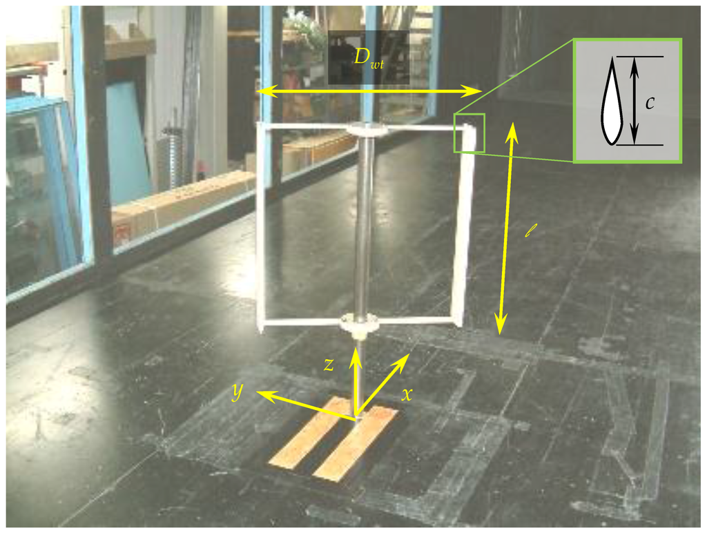
Figure 1.
Vertical-axis wind turbine used in the wind tunnel experiments.
A torque transducer (rating: 5 N m) was connected to the wind turbine and an AC torque motor brake was set under it for the loading. See Table 1 for specifications on the transducer. We measured the torque Q (N m) with an accuracy of ±0.2% and rotational speed n of the wind turbine under the condition of gradually increasing the turbine load from zero. The calculated power outputs P (W) = Q × 2πn are shown as performance curves.

Table 1.
Torque transducer and AC servo-control system.
3. Application of a Wind Lens with a Flat-Panel-Type Diffuser
3.1. Configuration of the Wind Lens
As shown in Figure 2, the VAWT was installed with a wind lens that was symmetrical about the direction of flow. The wind turbine had two blades (c = 0.15 m, airfoil: NACA0018) and the arms of the wind turbine held the blades at a distance of 0.4c m from the leading edge. The wind lens made of aluminum pipes and polystyrene panels and the diffuser unit consisted of flat panels. In Figure 2a, L is the diffuser length (m), h is the flange width (m), φ is the semi-open angle of the diffuser (°), D (=0.8 m) is the distance between the two sides of the wind lens at the throat, and W (=1.79D m) is the height of the wind lens. The wind lens covered the VAWT thoroughly in the vertical direction to minimize the influence of three-dimensional flows around the wind lens (i.e., ℓ = 0.7 m, W = 1.43 m, and the center of the wind turbine was located above the floor of the wind tunnel at z = 0.7 m).
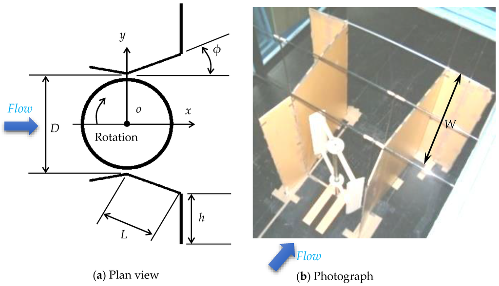
Figure 2.
Configuration of the wind lens: (a) plan view (the height of the wind lens is W); and (b) in situ photograph (L = 1.14D m, = 10°, h = 0.5D m).
3.2. Effect of Flange Width
Figure 3 shows power coefficient curves against tip speed ratio λ. The power coefficient is defined as Cp = P/(0.5 ρ·U03·A), where A (=ℓ Dwt·m) is the profile of the rotor area in the streamwise direction. The diffuser length L was 1.14D m, the semi-open angle φ was 20°, and the location of the wind lens in the streamwise direction was aligned with the center of the wind turbine (x = 0 m). We compared the power augmentation effects between h = 0.25D and h = 0.5D m. The results showed that a wind lens with wide flanges was more effective than one with narrow flanges. Furthermore, the power augmentation with the wind lens was a factor of 2.6 times that of an open wind turbine.
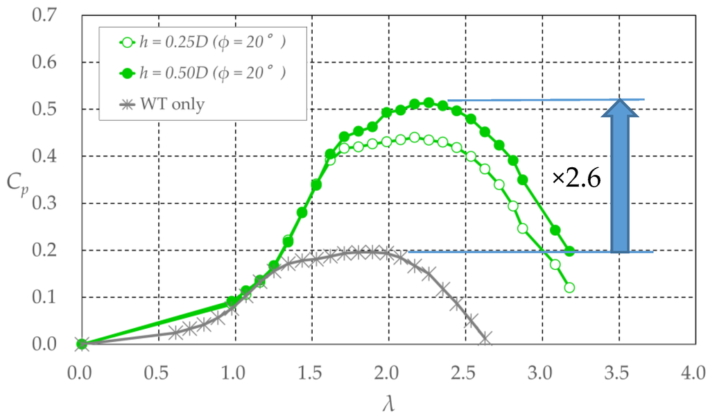
Figure 3.
Power coefficient Cp of wind turbines with and without a wind lens vs. tip speed ratio λ (diffuser length: L = 1.14D m). Refer to Figure 2 for h, D, L, and φ.
3.3. Effect of Open Angle of Diffuser
Figure 4 shows power coefficient curves against tip speed ratio λ when the open angle of the diffuser φ was varied from 5° to 20°. The diffuser length L was 1.14D m, the flange width h was 0.5D m, and the location of the wind lens in the streamwise direction was aligned with the center of the wind turbine (x = 0 m). The results showed that the larger the semi-open angle of the diffuser, the greater the increase of Cp. Furthermore, the increase in the semi-open angle of the diffuser made it possible to generate higher power output over a wider range of tip speed ratios.
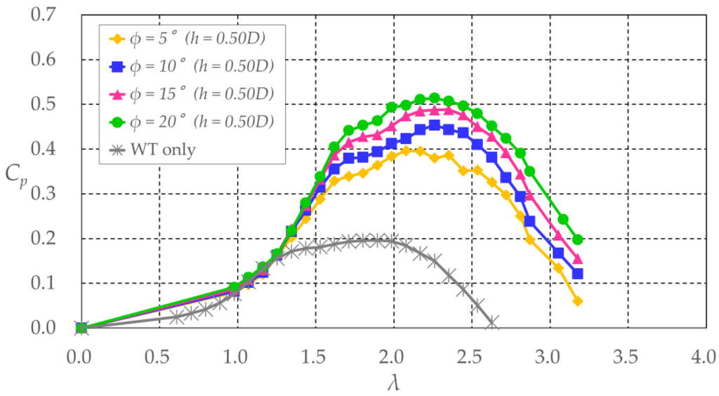
Figure 4.
Power coefficient Cp of wind turbines with and without a wind lens vs. tip speed ratio λ (diffuser length: L = 1.14D m). Refer to Figure 2 for h, D, and L.
We also compared Cp between wind lenses with the same projection area in the streamwise direction but different semi-open angles and flange widths (see Figure 5). The difference in Cp was not large within the range of λ > 2 and for maximum Cp; however, in the range of λ ≤ 2, the wind lens with the larger semi-open angle of the diffuser generated higher power output. Specifically, wind lenses with larger semi-open angles of the diffuser can generate higher power output over a wider range of tip speed ratios when those wind lenses have the same projection area within the streamwise direction.
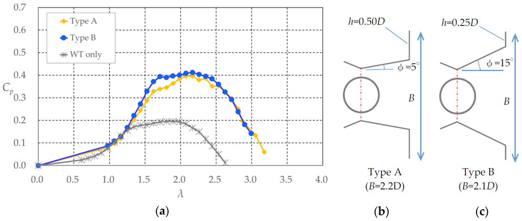
Figure 5.
(a) Power coefficient Cp of wind turbines with and without a wind lens vs. tip speed ratio λ (diffuser length: L = 1.14D m); (b) plan view of the wind lens of type A; and (c) plan view of the wind lens of type B. Refer to Figure 2 for h, D, and L.
3.4. Effect of Diffuser Length
The previous section confirmed the effectiveness of the semi-open angle of the diffuser on Cp. Making the diffuser length shorter without changing B (see Figure 6) creates a larger semi-open angle. Therefore, we configured a wind lens with half-length diffuser (L = 0.57D m) and examined its effect. The flange width h was 0.5D m. The results showed that a wind lens with a larger semi-open angle, created by shortening the length of the diffuser, could generate higher power output over a wider range of tip speed ratios. Furthermore, the maximum Cp was also increased.
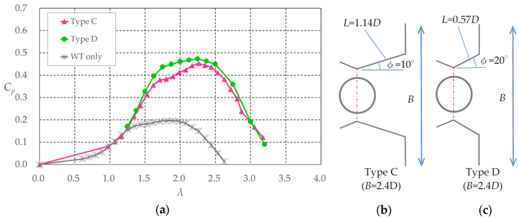
Figure 6.
(a) Power coefficient Cp of wind turbines with and without a wind lens vs. tip speed ratio λ (flange width: h = 0.5D m); (b) plan view of the wind lens of type C; and (c) plan view of the wind lens of type D. Refer to Figure 2 for h, and D.
With consideration of higher power output, we examined the effect of φ, using a wind lens with short-type diffuser (L = 0.57D m). We varied the semi-open angle of the diffuser φ from 10° to 30°. Figure 7 shows the power coefficient curves against tip speed ratio λ. For the case of φ = 30°, Cp hits a peak and it underruns the value of Cp for the case of φ = 20°, except around the peak. This indicates the existence of an optimum upper limit for the semi-open angle of the diffuser.
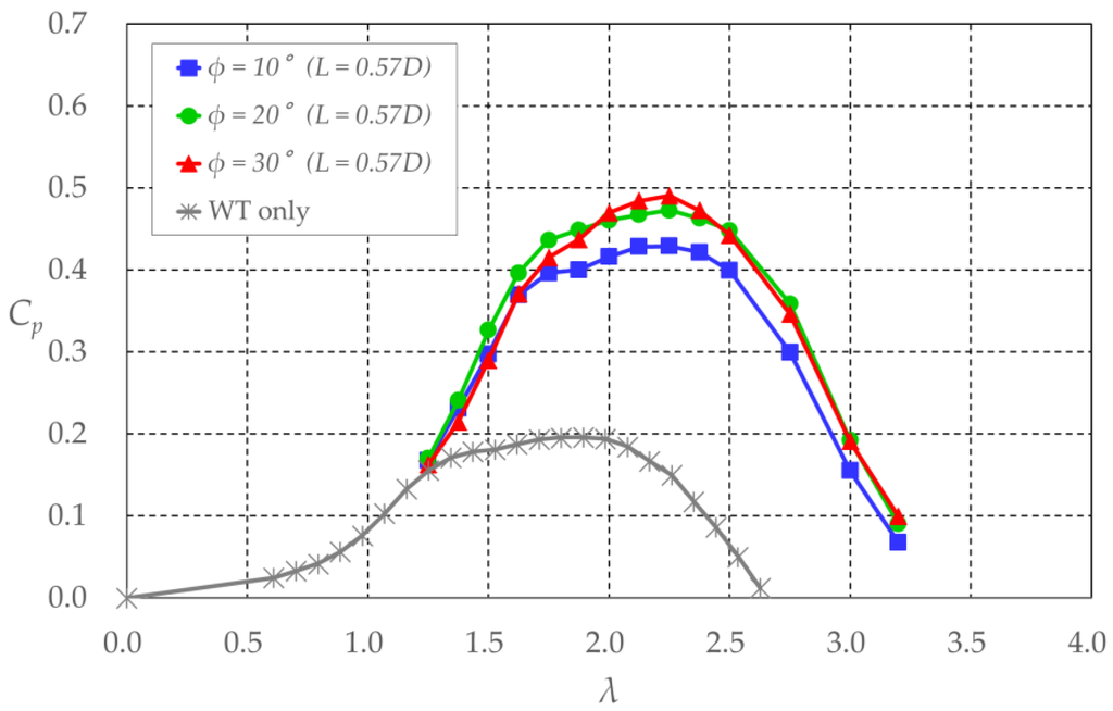
Figure 7.
Power coefficient Cp of wind turbines with and without a wind lens vs. tip speed ratio λ (diffuser length: L = 0.57D m). Refer to Figure 2 for D, and L.
3.5. Effect of the Inlet
Figure 8 shows power coefficient curves against tip speed ratio λ when the inlet part (with venturi configuration) of the wind lens was removed. The diffuser length L was 0.57D m, the flange width h was 0.5D m, and the semi-open angle of the diffuser φ was 20°. Overall, its absence had little effect on the maximum Cp, but the shrouded wind turbine without the inlet demonstrated higher output only within a narrow range of λ. Specifically, the inlet enhances power augmentation over a wider range of tip speed ratios.
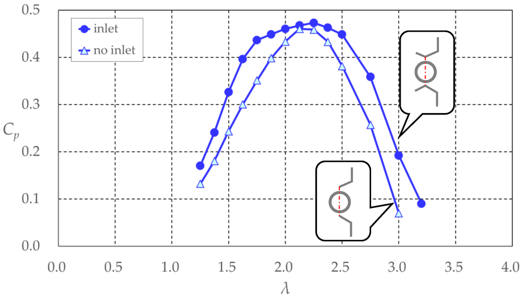
Figure 8.
Effect of the inlet of the wind lens on power coefficient Cp.
3.6. Effect of Wind Lens Location
The Venturi shape of a wind lens accelerates the wind at its throat [17]. Therefore, to generate the highest power output, the throat is the best location for a horizontal-axis wind turbine. However, the rotor of a VAWT extends in the streamwise direction, and therefore consideration should be given to the determination of the optimum position of a VAWT within a wind lens. We examined the effect of the location of the wind lens relative to the position of the VAWT in the streamwise direction. Figure 9 shows power coefficient curves against tip speed ratio λ when the location of throat of the wind lens was moved from x = −Dwt/2 to x = Dwt/2 m. The diffuser length L was 1.14D m, the flange width h was 0.5D m, and the semi-open angle of the diffuser φ was 15°. The results showed that to generate the highest power output, the center of the VAWTs (x = 0) is the best location for the throat of the wind lens. For the case of x = −Dwt/2 m, the maximum Cp was the lowest. For the case of x = Dwt/2 m, Cp showed an increase in the maximum value, but it did not reach the value for the case of x = 0. The shape of the power coefficient curve became more peaked when the throat of the wind lens was located behind the wind turbine. This is similar to the curve of the shrouded wind turbine with no inlet. Based on this result, it is assumed that an inlet is inefficient when located behind a wind turbine.
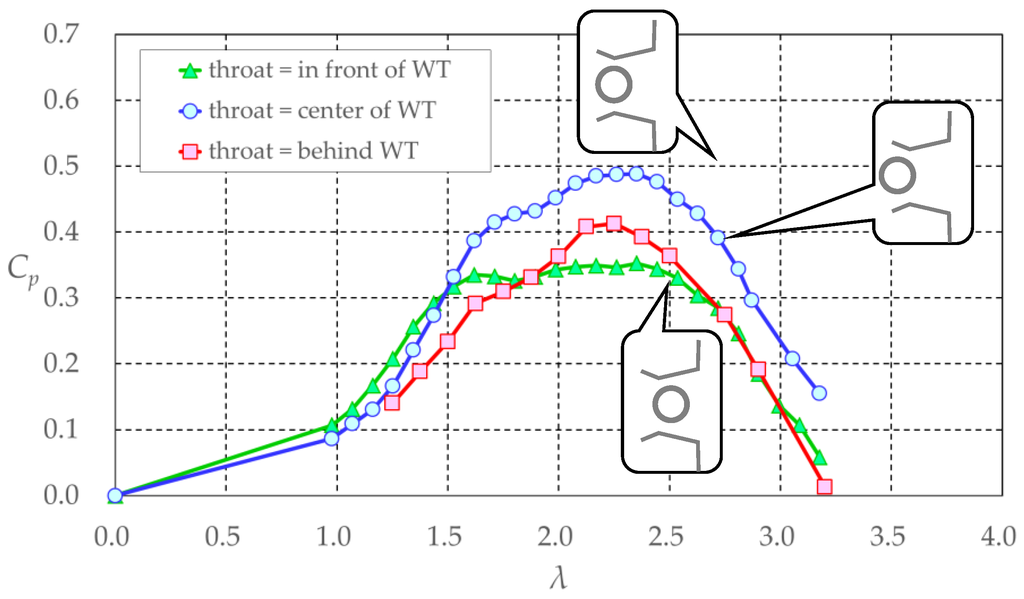
Figure 9.
Power coefficient Cp of wind turbines vs. tip speed ratio λ (diffuser length, L = 1.14D m; flange width, h = 0.5D m; semi-open angle of diffuser, φ = 15°). Refer to Figure 2 for h, D, and L.
The transitions of maximum Cp for the various configurations of the wind lens with a VAWT are summarized in Figure 10a. When the throat of the wind lens was located at the center of the wind turbine, larger semi-open angles of the diffuser led to an increase of Cpmax. When the throat of the wind lens was behind the wind turbine, the same tendency was produced. Generally, larger semi-open angles of the diffuser led to greater acceleration of the approaching wind by the wind lens. When the throat of the wind lens was in front of the wind turbine, larger semi-open angles of the diffuser led to a decrease of Cpmax. This was suspected to be due to the widening of the gap between the diffuser and the wind turbine through which the accelerated wind could flow. Based on the above results, the optimum location for a wind lens in the streamwise direction is aligned with the center of the VAWT.
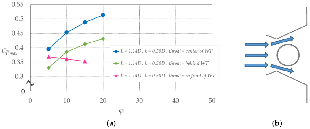
Figure 10.
(a) Maximum power coefficient Cpmax of wind turbines vs. semi-open angle of the diffuser φ; (b) Inferred flow when the throat of the wind lens is located in front of the wind turbine. Refer to Figure 2 for h, D, and L.
4. Application of a Wind Lens with a Curved-Surface-Type Diffuser
As shown in Figure 7, the larger the semi-open angle of the diffuser becomes, the greater the increase of Cp; however, Cp reaches a peak when the wind lens incorporates a flat-panel-type diffuser. Preventing this sluggishness might lead to further growth of the power output, and therefore we changed the diffuser to one with a curved surface, based on the expectation that the continuous expansion of the semi-open angle would prevent flow separation.
Figure 11 shows the configuration of a wind lens with a curved-surface-type diffuser. The configuration is based on the configuration of a wind lens with a flat-panel-type diffuser for which the semi-open angle φ = 20° and diffuser length L = 0.57D m. Shortening the width of the flanges from h = 0.5D to h = 0.25D m makes it possible for the broader expansion of the diffuser exhaust. The wind lens was made from wooden boards and acrylic panels. The dimensions of D and W were the same as for the case of the flat-panel-type diffuser. Furthermore, we used a wind turbine whose arms held the blades at a distance of 0.5c m from the leading edge, because Takahashi et al. [18] have shown that this configuration of a wind turbine is more efficient than one whose arms hold the blades at a distance of 0.4c m from the leading edge. The airfoil type was NACA0018 and the chord length was 0.15 m.
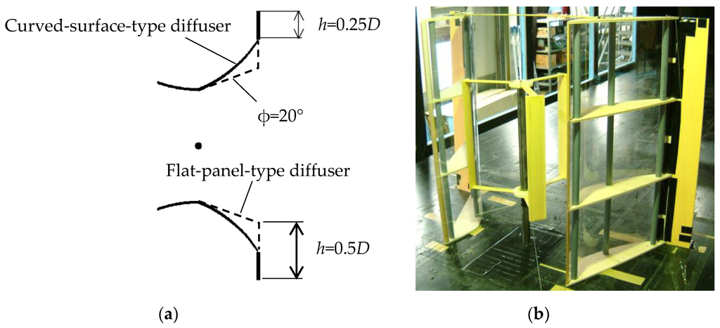
Figure 11.
Configuration of the wind lens with a curved-surface-type diffuser: (a) plan view and (b) in situ photograph. Refer to Figure 2 for D. (a) Plan view; (b) Photograph.
Figure 12 shows power coefficient curves against tip speed ratio λ. The shrouded wind turbines with a curved surface diffuser demonstrated higher power output than turbines with a flat-panel-type diffuser over the entire range of tip speed ratios. The wind lens with a curved diffuser demonstrated power augmentation by a factor of about 2.1 compared with an open wind turbine. According to the above results for the VAWTs and wind lenses considered, VAWTs shrouded within a curved-surface-type diffuser demonstrate higher power output and enhanced power augmentation over a wider range of tip speed ratios.
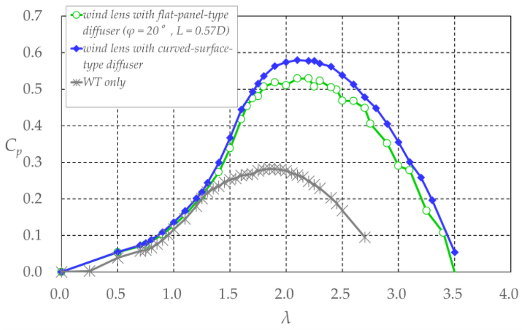
Figure 12.
Power coefficient Cp of wind turbines with and without a wind lens vs. tip speed ratio λ (curved-surface-type diffuser with flange width: h = 0.25D m). Refer to Figure 2 for h, D, and L.
5. Application of a Wind Lens to Various Configurations of Wind Turbines
Section 3 and Section 4 examined the effects of a wind lens on Cp when changing the configuration of the wind lens and its location relative to the VAWT. This section compares the power outputs of an open wind turbine and a wind turbine with a wind lens when changing the number of turbine blades, airfoil shape, and chord length. We used the wind lens with the flat-panel-type diffuser for which the diffuser length L = 0.57D m, flange width h = 0.5D m, and semi-open angle of the diffuser φ = 20°.
5.1. Effect of Number of Turbine Blades
Figure 13 shows power coefficient curves against tip speed ratio λ when wind turbines with two and three blades were used. The airfoil type was NACA0018 and the chord length was 0.15 m. The open wind turbine with two blades generated higher power output than the wind turbine with three blades, and the maximum Cp was found within the higher range of the tip speed ratio for the two-bladed turbine. The shrouded wind turbines exhibited the same tendencies, although the incorporation of the wind lens led to power augmentation by a factor of 1.9–2.1 compared with the open wind turbine.
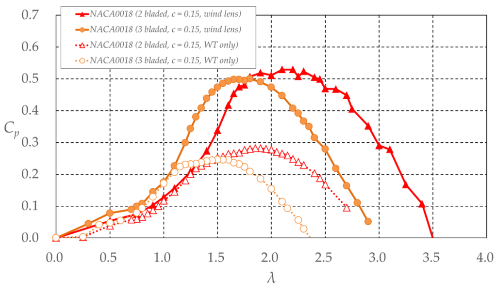
Figure 13.
Comparison of power coefficient Cp of two- and three-bladed wind turbines with and without a wind lens vs. tip speed ratio λ (wind lens: L = 1.14D m, h = 0.5D m, φ = 15°). Refer to Figure 2 for L, D, h, and φ.
5.2. Effect of Turbine Blade Thickness
Figure 14 shows power coefficient curves against tip speed ratio λ when the airfoil of the wind turbine was changed. The types of airfoils used were NACA0012, NACA0018, NACA0024, and NACA0030. The blades of these airfoils had different thicknesses. The number of blades was two, and the chord length was 0.15 m. The results showed that thicker turbine blades led to the maximum Cp at lower tip speed ratios and that the wind turbine with the NACA0024 airfoil generated the highest power output. Specifically, the thickest blades do not always generate the highest power output, and there is an optimum blade thickness for VAWTs. For the cases in which the wind lens was incorporated with the wind turbines, the same tendencies in power output were produced, although there was power augmentation by a factor of 1.9–2.2 compared with the open wind turbine.
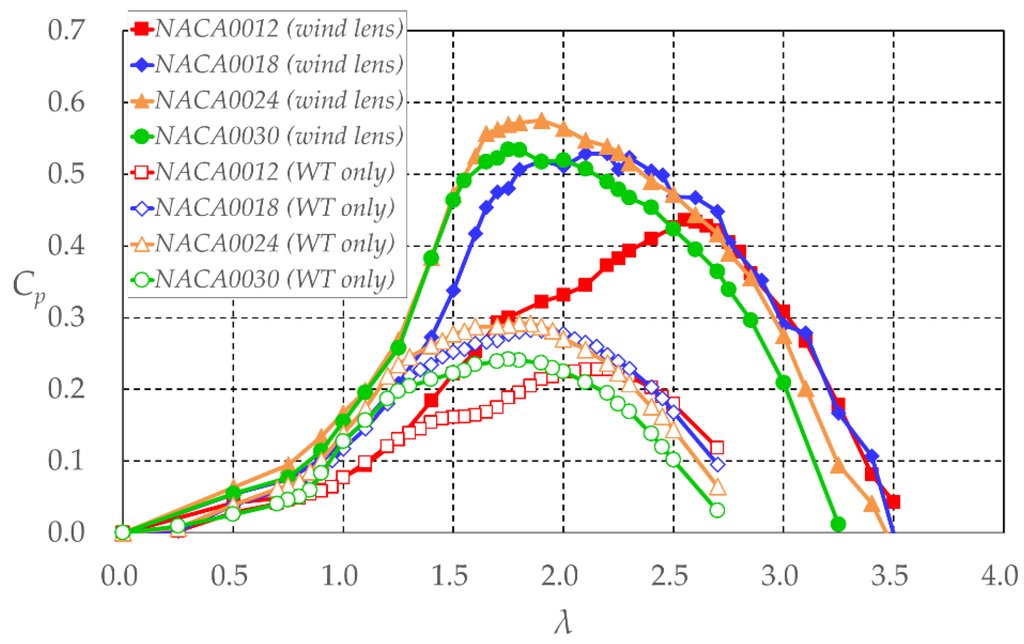
Figure 14.
Power coefficient Cp of wind turbines with airfoils of various thickness with and without a wind lens vs. tip speed ratio λ (wind lens: L = 1.14D m, h = 0.5D m, φ = 15°). Refer to Figure 2 for L, D, h, and φ.
5.3. Effect of Chord Length of Turbine Blades
Figure 15 shows power coefficient curves against tip speed ratio λ when the chord length of the turbine blades was changed. The airfoil type was NACA0024, the number of blades was two, and the chord length was 0.10 or 0.15 m. The results showed little difference in terms of maximum Cp between the two cases for an open wind turbine; the turbine with the shorter blades generated the maximum Cp within a higher range of tip speed ratios than the turbine with longer blades. For the cases in which the wind lens was incorporated with the wind turbines, the same tendencies in power output were produced, although there was power augmentation by a factor of 2.0 compared with the open wind turbine. Figure 13 and Figure 15 indicate that the turbine with the lower solidity generated the maximum Cp within a higher range of tip speed ratios. It is a same tendency as previous works [19,20].
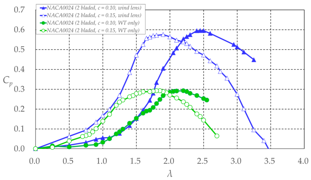
Figure 15.
Comparison of power coefficient Cp of wind turbines with different chord lengths with and without a wind lens vs. tip speed ratio λ (wind lens: L = 1.14D m, h = 0.5D m, φ = 15°). Refer to Figure 2 for L, D, h, and φ.
5.4. Effect of Number of Turbine Blades for Case with same Solidity
Figure 16 shows power coefficient curves against tip speed ratio λ when the number of turbine blades and chord lengths were changed but the solidity of the wind turbine remained the same. Solidity σ is defined as σ = (2 N·c)/Dwt, where N is the number of blades. For the case where N = 2, c was 0.15 m and where N = 3, c was 0.1 m (σ = 0.86). The results showed little difference in terms of maximum Cp between the two cases; however, for larger values of N, the lower the power output generated within the low range of tip speed ratios. Specifically, it is not always possible to obtain the same power output when σ is constant. For the cases in which the wind lens was incorporated with the wind turbines, the same tendencies in power output were produced, although there was power augmentation by a factor of 2.0–2.1 compared with the open wind turbine.
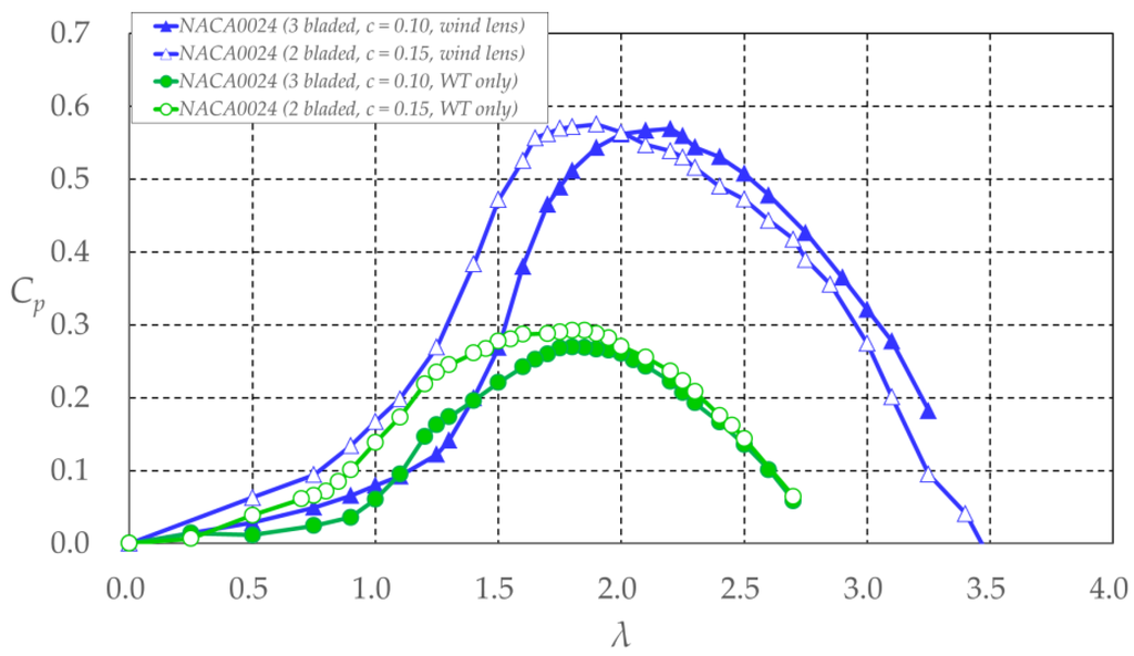
Figure 16.
Comparison of power coefficient Cp of wind turbines with same solidity and different blade numbers with and without a wind lens vs. tip speed ratio λ (wind lens: L = 1.14D m, h = 0.5D m, φ = 15°). Refer to Figure 2 for L, D, h, and φ.
Based on the above results, the incorporation of a wind lens demonstrates power augmentation equally irrespective of the configuration of the open wind turbine. Therefore, for maximum power output, it is important for a wind lens to be incorporated with an efficient open wind turbine.
6. Effect of Reynolds Number on Power Output
The effect of the Reynolds number on the power output of a VAWT with a wind lens was investigated by varying the approaching wind speed U0. For U0 = 6, 8, and 10 m/s, the Reynolds number, which is based on the chord length (c = 0.15 m) of the turbine blades, was 6.0 × 10⁴, 8.0 × 10⁴, and 10.0 × 10⁴, respectively. The types of airfoil used were a symmetric NACA0018 and an arc-shaped NACA0018. The arc-shaped airfoil had a centerline of curvature of R = Dwt/2 m. The curved-surface-type diffuser was used with the wind lens.
Figure 17 shows power coefficient curves against tip speed ratio λ. Higher values of power output were generated as the Reynolds number increased. The open wind turbine with arc-shaped blades did not generate as much power as the wind turbine with symmetric blades. The value of Cp of the open wind turbine with arc-shaped blades had high dependency on the Reynolds number. The Cp of the open wind turbine with symmetric blades reached a peak as the Reynolds number increased. These results indicated the existence of an upper limit to the power enhancement that can be derived from the increase of the Reynolds number. For the cases in which the wind lens was incorporated with the wind turbines, the same tendencies in power output were produced, although there was power augmentation by a factor of 2.1–2.2 compared with the open wind turbine. Furthermore, the incorporation of the wind lens enhanced the effect of the Reynolds number on power augmentation. For stable power output, it would be preferable to incorporate a wind lens with an open wind turbine for which the effect of the Reynolds number is small.
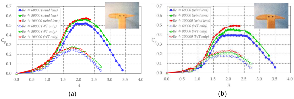
Figure 17.
Comparison of power coefficient Cp of wind turbines with various Reynolds numbers with and without a wind lens vs. tip speed ratio λ (wind lens: curved-surface-type diffuser). (a) NACA0018, symmetric; (b) NACA0018, arc-shaped.
7. Conclusions
We incorporated a wind lens in a VAWT and examined its effect on power augmentation using wind tunnel experiments. Various styles of wind lens have been applied to horizontal-axis wind turbines and similar technology should be effective for VAWTs.
First, we investigated the optimum parameters of the wind lens configuration. The wind lens with a flat-panel-type diffuser demonstrated power augmentation by a factor of 2.0 compared with an open wind turbine. The larger the semi-open angle of the diffuser became, the greater the power augmentation observed. The increase from 5° to 20° in the semi-open angle of the diffuser made it possible to generate a 30% high power output over a wider range of tip speed ratios. Furthermore, the larger the flange width became, the greater the observed power augmentation. For a constant area of projection in the streamwise direction, the wind lens with a larger semi-open angle of the diffuser could generate higher power output over a wider range of tip speed ratios; however, an optimum semi-open angle of the diffuser was established. For the flat-panel-type diffuser, a recommended diffuser length is 0.5D, and its semi-open angle is 20°. The inlet enhanced the power augmentation over a wider range of tip speed ratios, and the best location for the wind lens in the streamwise direction was aligned with the center of the VAWT. The curved-surface-type diffuser was more effective for power augmentation than flat-panel-type diffusers. The wind lens with a curved-surface-type diffuser demonstrated power augmentation by a factor of about 2.1 compared with the open wind turbine.
The power outputs of an open wind turbine and a wind turbine with a wind lens were compared when changing the configuration of the turbine, such as a number of blades, airfoil shape, and chord length. Irrespective of the turbine configuration, the incorporation of a wind lens demonstrated equal power augmentation. Therefore, power augmentation by the incorporation of a wind lens should be possible, even as the efficiency of the open wind turbine is improved.
The effect of the Reynolds number on the power output of a VAWT with a wind lens was investigated by changing the approaching wind speed. It would be preferable to incorporate a wind lens with an open wind turbine for which the effect of the Reynolds number is small, because the wind lens enhances the effect on power augmentation.
This study showed that a wind lens with a Venturi shape, curved diffuser, and shorter flanges (h = 0.25D m) was most effective in producing a greater power augmentation. The wind lens functions optimally when aligned with the center of the VAWT. Furthermore, it was demonstrated that a two-bladed wind turbine with NACA0024-type airfoils was most suitable for the incorporation of a wind lens to generate higher power output.
We are undertaking additional studies that address the influence of the diffuser on power augmentation. We are analyzing the flow around the VAWT by using flow visualization and CFD, however, it is clear that the whole flow passing VAWT is concentrated and accelerated by flanged diffuser similarly to HAWT [2]. That is, VAWT possibly demonstrate power augmentation by a factor of 2–3 because the flange of wind lens generates a low-pressure region in the exit neighborhood of the diffuser by vortex formation and draws more mass flow to the wind turbine inside the diffuser shroud.
Author Contributions
Koichi Watanabe and Shuhei Takahashi performed the experiments with supervision by Yuji Ohya. Koichi Watanabe analyzed the data. The manuscript was written by Koichi Watanabe and reviewed by Yuji Ohya.
Conflicts of Interest
The authors declare no conflicts of interest.
Abbreviations
The following abbreviations are used in this manuscript:
| VAWT | vertical-axis wind turbine |
| NACA | National Advisory Committee for Aeronautics |
| WT | wind turbine |
References
- Ohya, Y.; Karasudani, T.; Sakurai, A.; Abe, K.; Inoue, M. Development of a shrouded wind turbine with a flanged diffuser. J. Wind Eng. Ind. Aerodyn. 2008, 96, 524–539. [Google Scholar] [CrossRef]
- Ohya, Y.; Karasudani, T. A shrouded wind turbine generating high output power with wind-lens technology. Energies 2010, 3, 634–649. [Google Scholar] [CrossRef]
- Gilbert, B.L.; Foreman, K.M. Experiments with a diffuser-augmented model wind turbine. J. Energy Resour. Technol. 1983, 105, 46–53. [Google Scholar] [CrossRef]
- Andrew, S.; Velissarios, K. Application of Circulation Controlled Blades for Vertical Axis Wind Turbines. Energies 2013, 6, 3744–3763. [Google Scholar]
- Travis, J.C.; Brian, H.D.; Zhen, X.H.; Bo, P.W. Aerodynamic Shape Optimization of a Vertical-Axis Wind Turbine Using Differential Evolution. ISRN Renew. Energy 2012, 2012, 1–16. [Google Scholar]
- Andrea, A.; Antonio, E.; Antonio, M.; Calogero, O.; Davide, T. 3D CFD Analysis of a Vertical Axis Wind Turbine. Energies 2015, 8, 3013–3033. [Google Scholar]
- Chao, L.; Songye, Z.; You-lin, X.; Yiqing, X. 2.5D Large Eddy Simulation of Vertical Axis Wind Turbine in High Angle of Attack Flow. Renew. Energy 2013, 51, 317–330. [Google Scholar]
- Rosario, L.; Stefano, M.; Michele, M. 2D CFD Modeling of H-Darrieus Wind Turbines Using a Transition Turbulence Model. Energy Procedia 2014, 45, 131–140. [Google Scholar]
- Sina, S.; Fernando, P.A. Large Eddy Simulation of Vertical Axis Wind Turbine Wakes. Energies 2014, 7, 890–912. [Google Scholar]
- Fujisawa, N.; Shibuya, S. Observations of Dynamic Stall on Darrieus Wind Turbine Blades. J. Wind Eng. Ind. Aerodyn. 2001, 89, 201–214. [Google Scholar] [CrossRef]
- Chong, W.T.; Naghavi, M.S.; Poh, S.C.; Mahlia, T.M.I.; Pan, K.C. Techno-economic analysis of a wind-solar hybrid renewable energy system with rainwater collection feature for urban high-rise application. Appl. Energy 2011, 88, 4067–4077. [Google Scholar] [CrossRef]
- Chong, W.T.; Fazlizan, A.; Poh, S.C.; Pan, K.C.; Hew, W.P.; Hsiao, F.B. The design, simulation testing of an urban vertical axis wind turbine with the Omni-direction guide vane. Appl. Energy 2013, 112, 601–609. [Google Scholar] [CrossRef]
- Daegyoum, K.; Morteza, G. Efficiency improvement of straight-bladed vertical-axis wind turbines with an upstream deflector. J. Wind Eng. Ind. Aerodyn. 2013, 115, 48–52. [Google Scholar]
- Watanabe, K.; Ohya, Y.; Karasudani, T.; Watanabe, K. Application of collection-acceleration device of wind to VAWT. In Proceedings of the Japan Wind Energy Symposium, Tokyo, Japan, 20 November 2004; Volume 26, pp. 147–150. (In Japanese)
- Takahashi, S.; Ohya, Y.; Karasudani, T.; Watanabe, K. Numerical and experimental studies of Airfoils suitable for Vertical axis wind turbines and an application of wind-energy collecting structure for higher performance. In Proceedings of the Fourth International Symposium on Computational Wind Engineering (CWE 2006), Yokohama, Japan, 16–19 July 2006; pp. 327–330.
- Watanabe, K.; Ohya, Y.; Karasudani, T. Development of a high-performance Vertical axis wind turbine by a drive. In Proceedings of the National Symposium on Wind Engineering, Tokyo, Japan, 1–3 December 2010; pp. 239–244. (In Japanese)
- Ohya, Y.; Uchida, T.; Karasudani, T.; Hasegawa, M.; Kume, H. Numerical Studies of Flow around a Wind Turbine Equipped with a Flanged-Diffuser Shroud Using an Actuator-Disk Model. Wind Eng. 2012, 36, 455–472. [Google Scholar] [CrossRef]
- Takahashi, S.; Hamada, J.; Ohya, Y.; Karasudani, T. Numerical and experimental studies of Airfoils suitable for Vertical axis wind turbines and an application of wind-energy collecting structure. In Proceedings of the National Symposium on Wind Engineering, Tokyo, Japan, 29 November–1 December 2006; pp. 169–174. (In Japanese)
- Seki, K.; Otani, I. Performance of Straight Blade, Non-Articulated Vertical Axis Wind Turbine. J. JSES 1990, 16, 31–38. (In Japanese) [Google Scholar]
- Okubayashi, T.; Kage, K.; Ishimatsu, K.; Hamakawa, H.; Date, H. Experimental Study of Darrieus Wind Turbine; Oita University: Oita, Japan, 1996; Volume 33, pp. 17–22. (In Japanese) [Google Scholar]
© 2016 by the authors; licensee MDPI, Basel, Switzerland. This article is an open access article distributed under the terms and conditions of the Creative Commons Attribution (CC-BY) license (http://creativecommons.org/licenses/by/4.0/).