1. Introduction
The origin of multiphase motor drives dates back to 1969 when a five-phase voltage source inverter-fed induction motor drive was proposed [
1]. Until the 1990s, due to the technological advancements in semiconductor devices and as for the emerging development of high-power applications, such as electric ship propulsion, locomotive traction, electric and hybrid electric vehicles, and “more-electric” aircraft, it has witnessed a surge of research interest within the drives research community [
1,
2]. The primary utilization of a multiphase motor drive is restricted to specialized applications where a conventional three-phase drive does not meet the requirements. However, it possesses many other attractive features over their three-phase counterparts, such as higher efficiency, greater fault tolerance, smaller pulsating torques, increased power in the same frame, and so on [
1,
2,
3]. Thus, many researchers have discussed the various issues related to the use of multiphase motor as an alternative to the three-phase motor [
4,
5,
6,
7].
The medium-voltage (MV) drives have found widespread applications in industry [
8,
9,
10,
11]. A general block diagram of the typical MV drives available on the market is introduced in [
11]. All of them have the exact same feature; that the phase-shifting transformer with multiple secondary windings is usually used for the reduction of line current harmonics and isolation between the power source and the motor. With the goal of eliminating this heavy and costly phase-shifting transformer, some significant work has been done [
12,
13,
14,
15,
16,
17,
18,
19]. Reference [
12] presents a hybrid cascaded H-bridge multilevel motor drive control scheme for electric/hybrid electric vehicles. A sensorless drive of a three-phase induction motor is introduced in [
17]. In [
18], a transformerless hybrid active filter is integrated into a conventional MV motor drive system to mitigate harmonic currents. A theoretical transformerless cascaded AC-DC-AC converter for multiphase propulsion drive is proposed in [
19]. However, less attention was paid to the areas of the high efficiency and high performances of MV multiphase motor drives.
In this paper, a transformerless MV multiphase motor drive scheme is proposed based on the cascaded H-bridge converter technique. An improved PD-PWM method aiming at balancing DC-link capacitor voltages for the proposed drive system is presented. A downscale nine-phase motor drive system is designed and constructed. The experimental results verify the viability and effectiveness of the proposed motor drive system. This paper is presented as follows. (1) A brief introduction of the proposed transformerless motor drive is described in
Section 2; (2)
Section 3 states the overall control scheme of the system; (3) the principle and implementation of the improved PD-PWM for DC voltage balancing is discussed in
Section 4; (4) the experimental results are represented in
Section 5; (5) finally, conclusions and future extensions of this research are summarized in
Section 6.
2. System Configuration
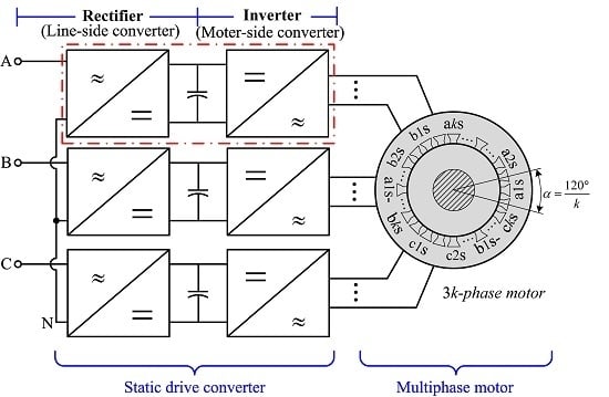
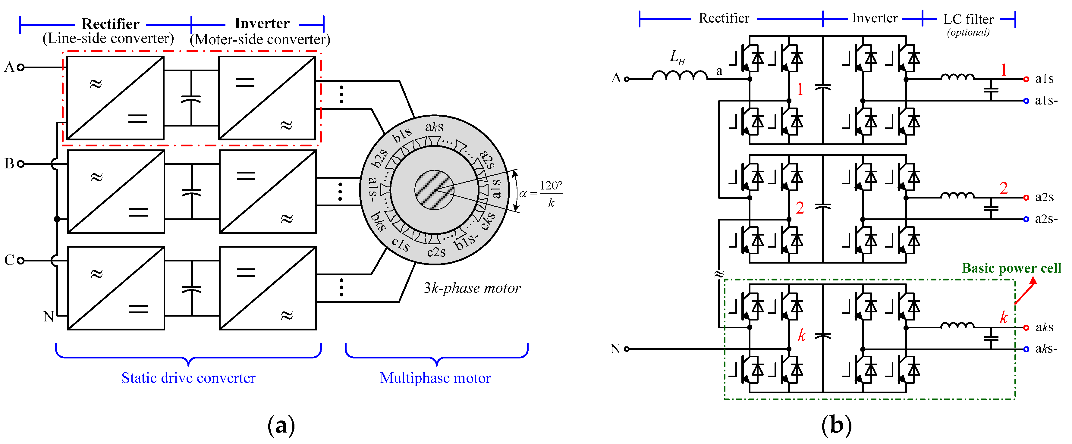
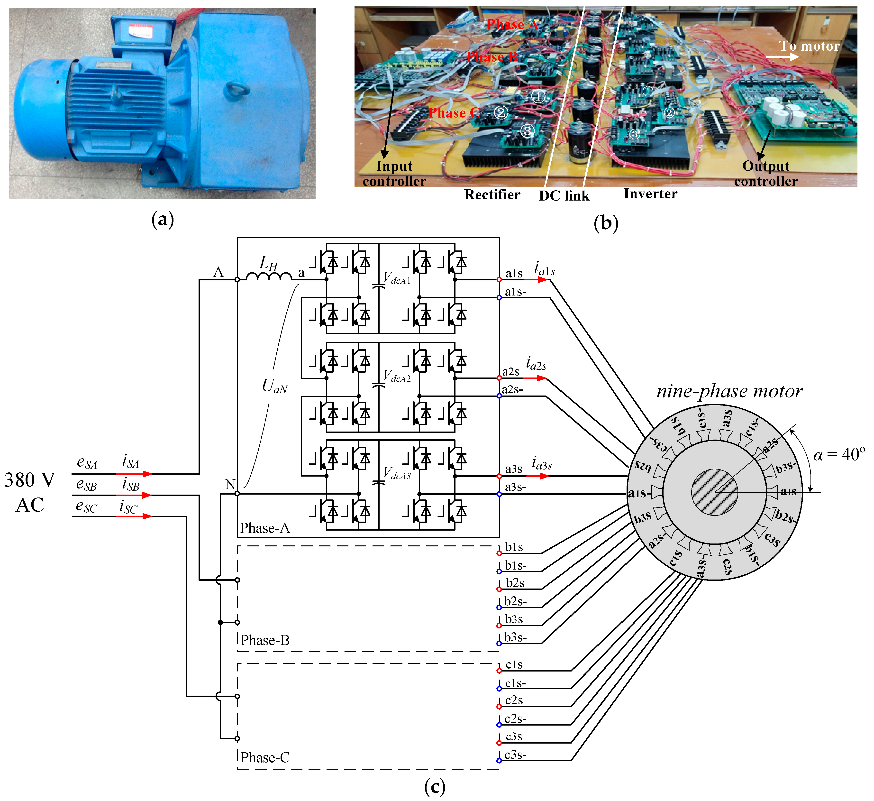
Figure 1 shows the proposed transformerless MV multiphase motor drive system configuration. The drive system consists of a static drive converter and a multiphase motor (e.g., 3
k-phase motor). The static drive converter is a three-phase-input and multiphase-output two-stage voltage source converter (VSC). For the convenience of discussion, we still call the drive converter a three-phase system. The input terminals of the converter, in a Y-type configuration, are directly connected to the three-phase MV distribution systems. The output terminals of the drive converter are connected to the stator terminals of the multiphase motor. Herein, compared with the conventional MV drives, the line-side phase-shifting transformer is removed, which results in the reduction of space, weight, and cost requirements.
Each phase of the drive converter consists of a line inductor (
LH) and
k identical basic power cells of which inputs (line side) are connected in series to fabricate the phase-to-neutral voltage matched with the grid and outputs feed the related motor stator windings. Each power cell includes a front-end three-level (3L) H-bridge converter, a capacitive DC link, a back-end 3L H-bridge inverter, and an optional LC filter. As shown in
Figure 1b, the
k front-end H-bridges are cascaded to interconnect with the power source (e.g., MV distribution systems), and the
k back-end H-bridges form
k independent single-phase outputs for feeding the multiphase motor. The cascaded H-bridges with the line inductor works as an active pulse-width modulation (PWM) rectifier. The cascaded H-bridge structure (known as cascaded multilevel converter) has attractive advantages in applications of the high-power MV and high-voltage (HV) drives with frequency modulation control [
20]. In the proposed scheme, the cascaded multilevel converter technique makes semiconductor devices with voltage and current limitation can be used in the converter or inverter which is directly connected to the MV power grid without any isolation transformer. In addition, based on this structure, the power can bidirectionally flow between the grid and motor, which means that the energy of the motor will be fed back to the grid when the motor is in braking. Therefore, the brake circuit can be abandoned.
For the proposed drive system, the input high voltages are divided equally between the cascaded basic power cells and rectified to DC voltages. Then, the DC voltage in each basic power cell is inverted into AC voltage to power the corresponding winding of the multiphase motor.
Assuming the DC-link voltage to be Vdc, each H-bridge can fabricate three voltage levels, namely, +Vdc, 0, and −Vdc. Therefore, the rectifier with k H-bridges in a cascade can produce 2k + 1 voltage levels per phase on the AC terminals. It more accurately portrays a sinusoidal waveform than a conventional single 3L H-bridge converter, which makes small AC-side filter requirements. Furthermore, this can guarantee to obtain high-quality AC waveforms at low device switching frequencies which can reduce switching losses.
The value of “
k” (number of basic power cells per phase) depends on the voltage level of the power source, the rated voltage of the semiconductor devices, and the number of the stator windings of the motor. It can be calculated by Equation (1) when taking insulated gate bipolar transistors (IGBTs) with voltage rating
VD as the power switches for the drive converter, assuming that the stator windings can always match the requirements.
where
E is the rms value of the line-to-line voltage of the source, η is voltage margin coefficient.
The maximum AC terminal voltage
U of a single power cell is:
where
m is modulation index of the line-side H-bridge converter. This voltage is also the maximum voltage that the motor-side H-bridge inverter can fabricate.
For example, the supply voltages for motors of which power is upward of 200-kW are mostly 6 kV and 10 kV in China [
21]. Correspondingly, the number of the basic power cells connected in series at the input side per phase may be not less than three and five if 3.3 kV IGBTs are used. At the same time, the rated voltage of the stator windings of the multiphase motor can be set at about 1300 V. Apparently, the proposed drive converter is a buck scheme. According to the actual input voltage levels and motor power ratings, the number of the power cells of each phase could be increased to reduce semiconductor device voltage stresses and power requirements.
Since the motor drive converter has k outputs per phase, the number of the phases (stator windings) of the multiphase motor should be 3k to achieve power balance between the high-voltage three-phase input side and the low-voltage multiphase output side. In other words, the proposed drive system is suitable for the triple stator winding multiphase motor.
If the concentrated winding technique is adopted, the equivalent mechanical angle of adjacent stator windings is:
In addition, unlike conventional MV drive systems using the phase-shifting transformer providing electrical isolation, the proposed multiphase motor drive system achieves electrical isolation by its independent and isolated stator windings because the 3k output voltages of the drive converter are not isolated electrically from each other. That is, the phase windings of the multiphase motor must be designed to be magnetically contacted but not to be electrically contacted. Although the voltage rating of each phase of the multiphase motor is only 1/k of the input grid voltage, the insulation should be designed carefully as different stator windings may work at different electric potentials which depend on the position of the basic power cells their connected. For example, the insulation between the adjacent windings can be mainly considered according to the rated voltage of each phase of the multiphase motor if the related power cells belong to the same input phase (A, B, or C). However, the insulation between the windings should be designed based on the voltage level of the grid if the related power cells belong to different input phases, respectively. Of course, the insulation requirement between the windings and case should be treated as the same as that of their MV three-phase counterparts.
Another important issue concerns the common-mode voltage which is usual in power electronics converter-fed drives [
13,
14]. The common-mode voltage would appear on the multiphase motor causing premature failure of its winding insulation if not mitigated. For the custom-made multiphase motor, the solution is that the motor can be designed with enhanced insulation to withstand common-mode voltage stresses. Another solution is to use active switching methods by which the common-mode voltage can be reduced or eliminated [
15,
16].
As analysed above, the proposed drive system can cover the main functions of the phase-shifting transformer in traditional multipulse MV drive systems: (1) harmonic cancellation provided by line-side cascaded H-bridges; (2) proper voltages for the motor fed by H-bridge inverters; (3) electrical isolation provided by the stator windings of the multiphase motor. Thus, the phase-shifting transformer can be cancelled.
3. Control Scheme
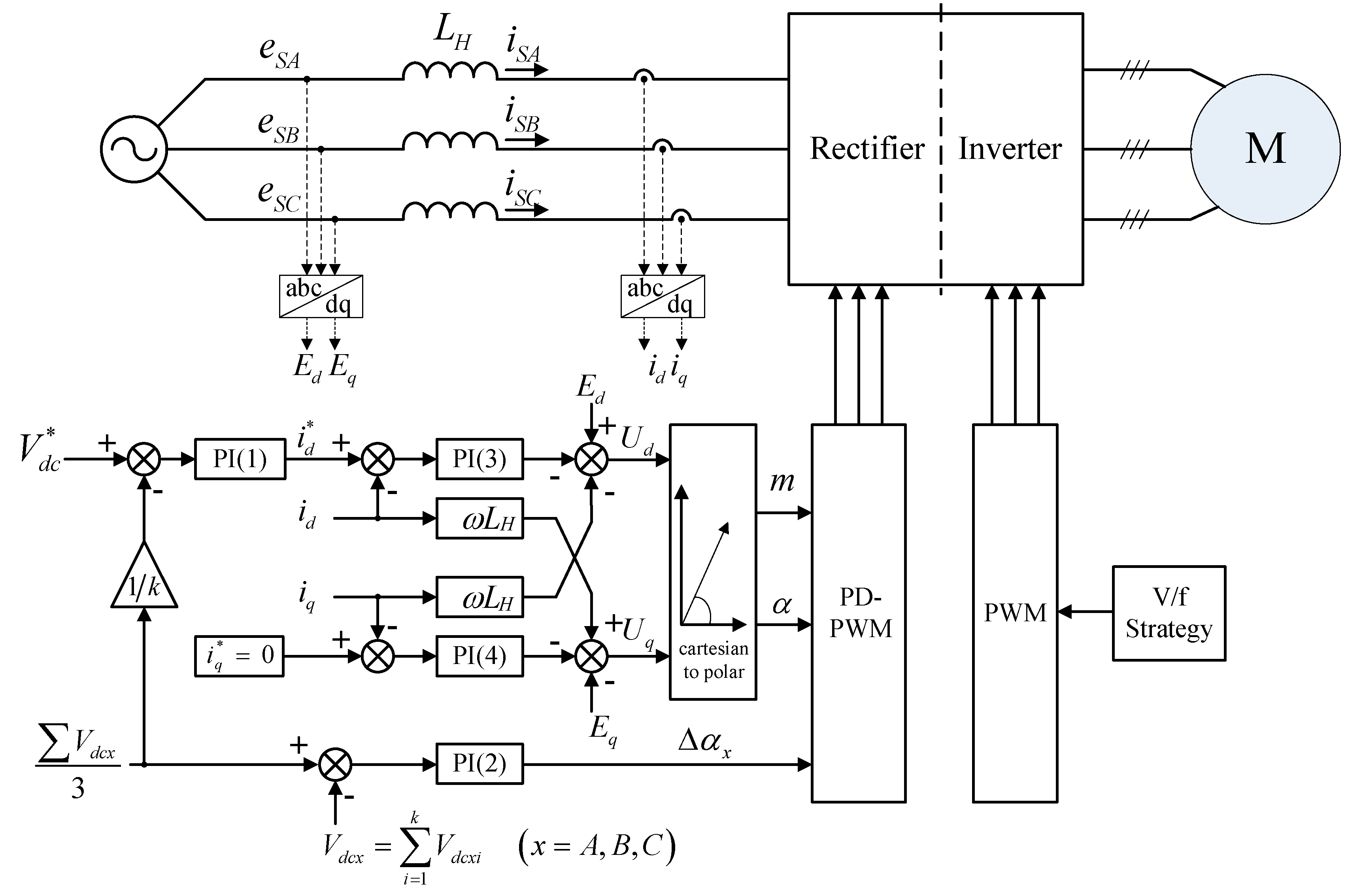
A reliable control system and control strategy are required for the proposed drive system. Based on the structural features of the proposed system, the control strategy can be divided into two decoupled parts: A line-side control strategy, and a motor-side control strategy. The former is for the three-phase cascaded H-bridge rectifier, and the latter is for the 3k-phase H-bridge inverter. The DC-link voltage balancing control is a challenge for the proposed drive system since the cascaded H-bridge rectifier is loaded by independent H-bridge inverters. This issue will be discussed in the next section. Herein, the overall control strategy is merely depicted.
As shown in
Figure 1, the line-side converter (rectifier) is a typical three-phase VSC. It aims to establish constant DC-link voltages and sinusoidal AC input currents, which is generally realized by a closed-loop control. Thus, the classical two loop control (a DC voltage outer loop and an AC current inner loop) is proposed for the rectifier, as shown in
Figure 2. The average of DC-link voltages is compared with the reference
. The error signal is inputted to the PI regulator to generate the reference
for the inner control loop. In addition, the individual DC-link voltages are compared with the average to generate additional phase-shifts (Δα
x) through a PI regulator to correct the delay angles (α), which can balance the individual DC-link voltage more. A decoupled state-feedback control technique in direct-quadrature (d-q) synchronous reference frame is adopted in the AC current loop. The mathematical expression of this control strategy is shown as [
22]:
where
Ed and
Eq are the source voltages,
id and
iq are the line currents,
Ud and
Uq are the AC terminal voltages of the rectifier, ω is the synchronous angular velocity,
LH is the line inductance,
Kp is the proportional gain, and
KI is the integral gain.
is the reference of the active power component of the line current, which is derived from the dc voltage control loop.
is the reference of the reactive power component of the line current. Here,
is set to zero to maintain unity power factor on the grid side.
The DC-link voltages can be maintained at the desired reference value and the input AC currents can be controlled to be symmetrical and sinusoidal with the control strategy depicted above. For the motor-side inverters, various control schemes, such as volts-per-hertz (V/f) control, field-oriented control (FOC), direct torque control (DTC), can be adopted. For simplicity, the conventional V/f control is used in this paper. The overall control diagram is illustrated in
Figure 2.
4. DC-Link Voltage Balancing Strategy
For the separate DC-link converter topology, like the cascaded multilevel converter used in the proposed drive system, it is a problem to ensure that individual DC-link voltages for each power cell are always balanced, which is very important to limit voltage and current stresses on the power cells and to ensure controllability. Moreover, the problem will become severe if the loads are not balanced. Some researchers have discussed the related topics. In [
23], Selective Harmonic Elimination (SHE) is introduced to solve this problem, but it is only for the case in which the switching frequency is very low. A passivity-based controller for DC-link voltage balancing is designed in [
24]; nevertheless, the algorithm is very complicated. In [
25], several PI regulator-based DC-link voltage balancing solutions for the single-phase H-bridge multilevel active rectifier are summarized, while a huge number of PI regulators are needed when more H-bridges are cascaded. In [
26], a phase-disposition PWM (PD-PWM) method for DC-link voltage balancing in the two-cell cascaded H-bridge rectifier is introduced, however, how to generalize it for three or more cells case is unclear and the details of the realization are not presented. In this paper, an improved PD-PWM method is proposed and is implemented with the help of a digital signal processor (DSP).
4.1. Voltage Balancing Scheme Using Improved PD-PWM
The PD-PWM is based on position shifts between carriers. Each carrier is associated with the specified voltage level. The corresponding voltage level is generated when the modulating wave is over its carrier wave. Therefore, if the PD-PWM is used in cascaded H-bridge converters, the H-bridge cell works only when the corresponding voltage level is reached, which produces an uneven power distribution between cells to cause the unbalanced DC-link voltages. However, this inherent uneven power distribution characteristic of the PD-PWM can be used for the proposed drive system to relieve the DC-link voltage unbalancing stresses caused by unbalanced loads (e.g., some stator windings failure of the multiphase motor). The principle is to match the uneven power distribution caused by the PD-PWM and those caused by the unbalanced loads, which is realized by regulating the charging or discharging times of the DC-link capacitors via modifying the PD-PWM. In this case, we call it improved PD-PWM.
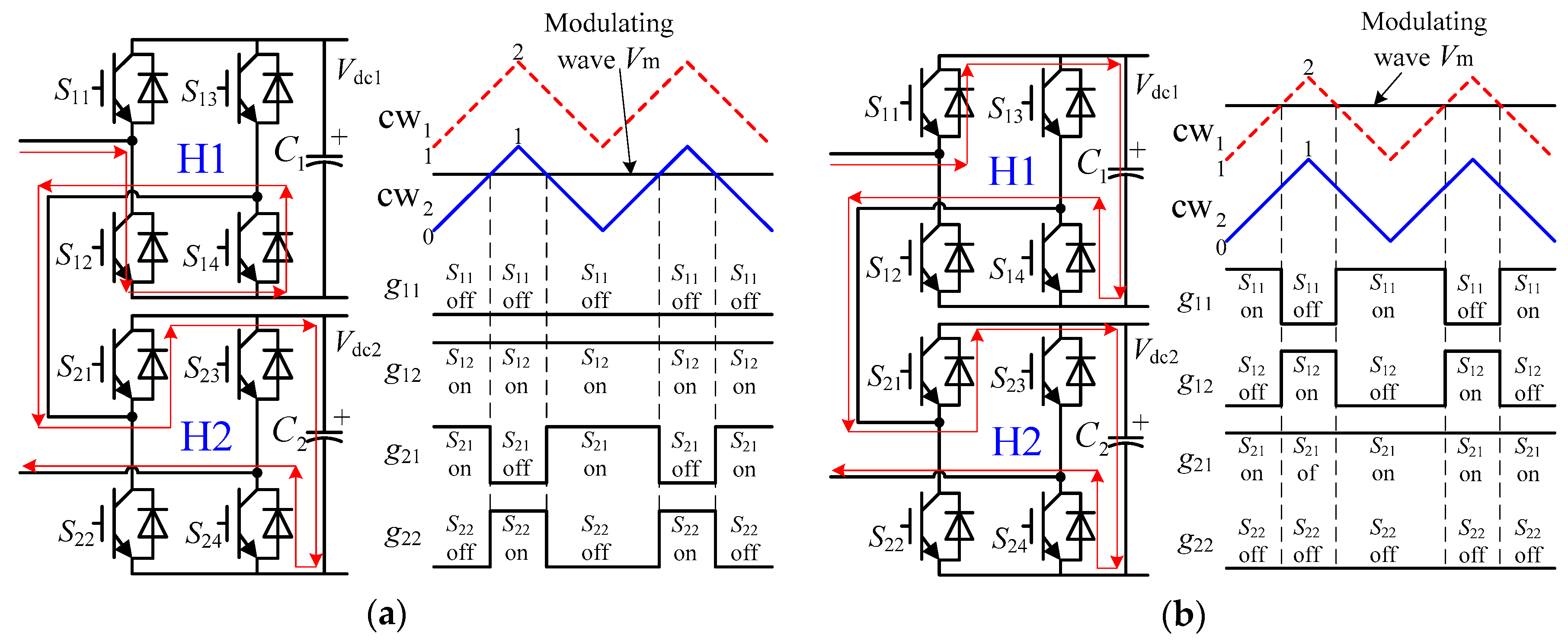
This depends on the differences between the DC-link voltages and the direction of AC currents to control the charging or discharging times of the DC-link capacitors. For the convenience of discussion, two-cell H-bridge cascaded rectifier, as shown in
Figure 3, is used to explain the operating principle of the improved PD-PWM in this section. The detailed implementation for a cascaded converter implementing more than two cells will be presented in the next section.
Considering the modulating wave in the positive half-cycle, keep switches S13 and S23 off, and switches S14 and S24 on. Assuming that the DC capacitor voltage Vdc1 is greater than Vdc2, the principle of operation is as follows:
The carrier wave cw
2 for the second H-bridge (H2) is placed beneath the carrier wave cw
1 for the first H-bridge (H1) when the direction of the input AC current is from the AC source to the converter (positive,
Idir > 0). Then, the switching modes of
S11,
S12,
S21, and
S22 are as shown in
Figure 3. The charging times for the DC capacitor
C1 and
C2 in a switching cycle are
or
where
TC1.charing and
TC2.charing are the charging times for
C1 and
C2, respectively.
Vm is the instantaneous value of the modulating wave.
TS is the switching cycle.
As can be seen from Equation (6), the charging process of the capacitor C2 is longer than that of the capacitor C1, which means that the capacitor C2 obtains much more active power than the capacitor C1 during that time interval, and the DC voltage Vdc2 increases relatively more than Vdc1. Therefore, the DS-link voltages Vdc1 and Vdc2 become equal slowly.
When the direction of the input AC current is negative (
Idir < 0), as shown in
Figure 4, the carrier wave cw
2 is placed upon the carrier wave cw
1. The discharging times for the DC bus capacitors
C1 and
C2 in a switching cycle are:
or
where
TC1.discharing and
TC2.discharing are the discharging times for
C1 and
C2, respectively.
Obviously, the discharging process of the capacitor C2 is shorter than that of the capacitor C1, which means that the capacitor C2 releases fewer active power than the capacitor C1, and the DC voltage Vdc2 decreases relatively less than Vdc1. Therefore, the DC-link voltages Vdc1 and Vdc2 become equal.
Similarly, the modulation principle can also be drawn out in the negative half-cycle of the modulating wave. As a result, the DC-link voltage balancing control in the line-side cascaded H-bridge rectifier of the proposed drive system can be achieved by adjusting the relative position of carrier waves repeatedly in accordance with the direction of AC currents.
Table 1 and
Table 2 present the complete modulation strategy. The proposed modulation method is not only suitable for a two-cell cascaded H-bridge converter, but also suitable for a three, or more, cell cascaded H-bridge converter.
4.2. Implementation of Improved PD-PWM in DSP
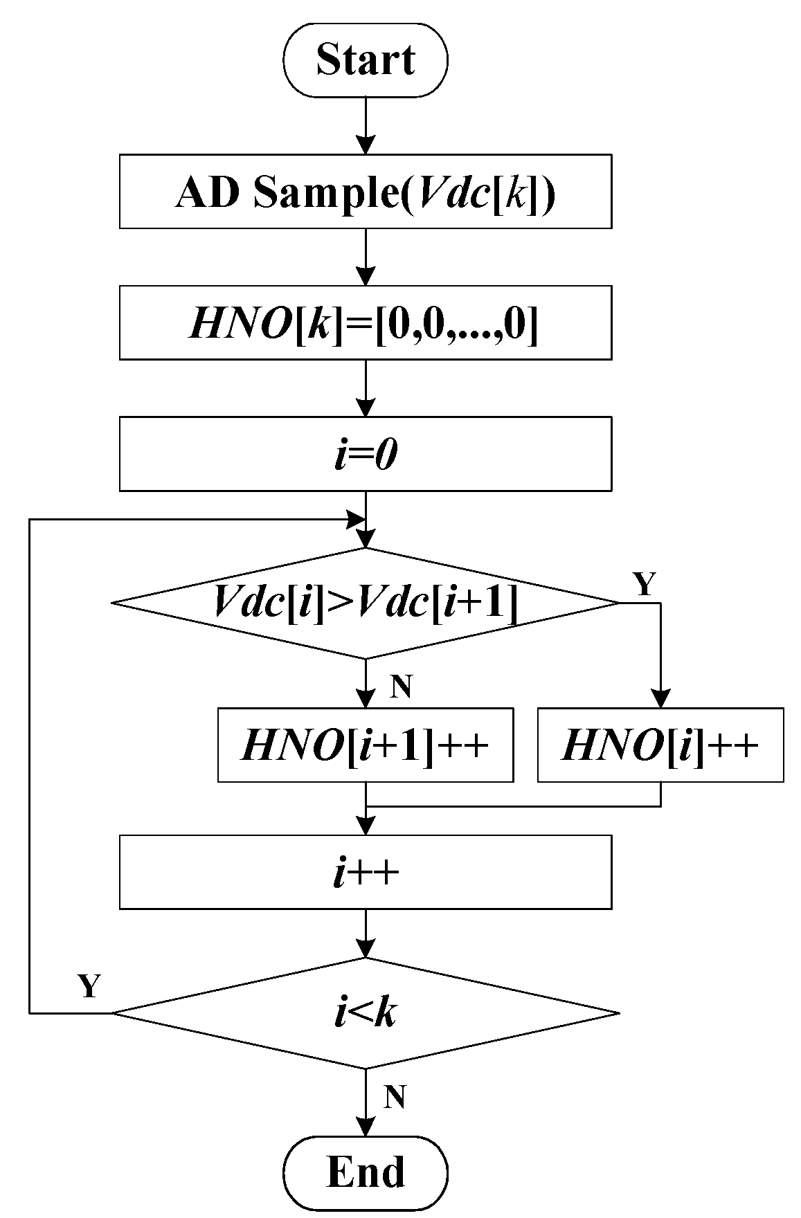
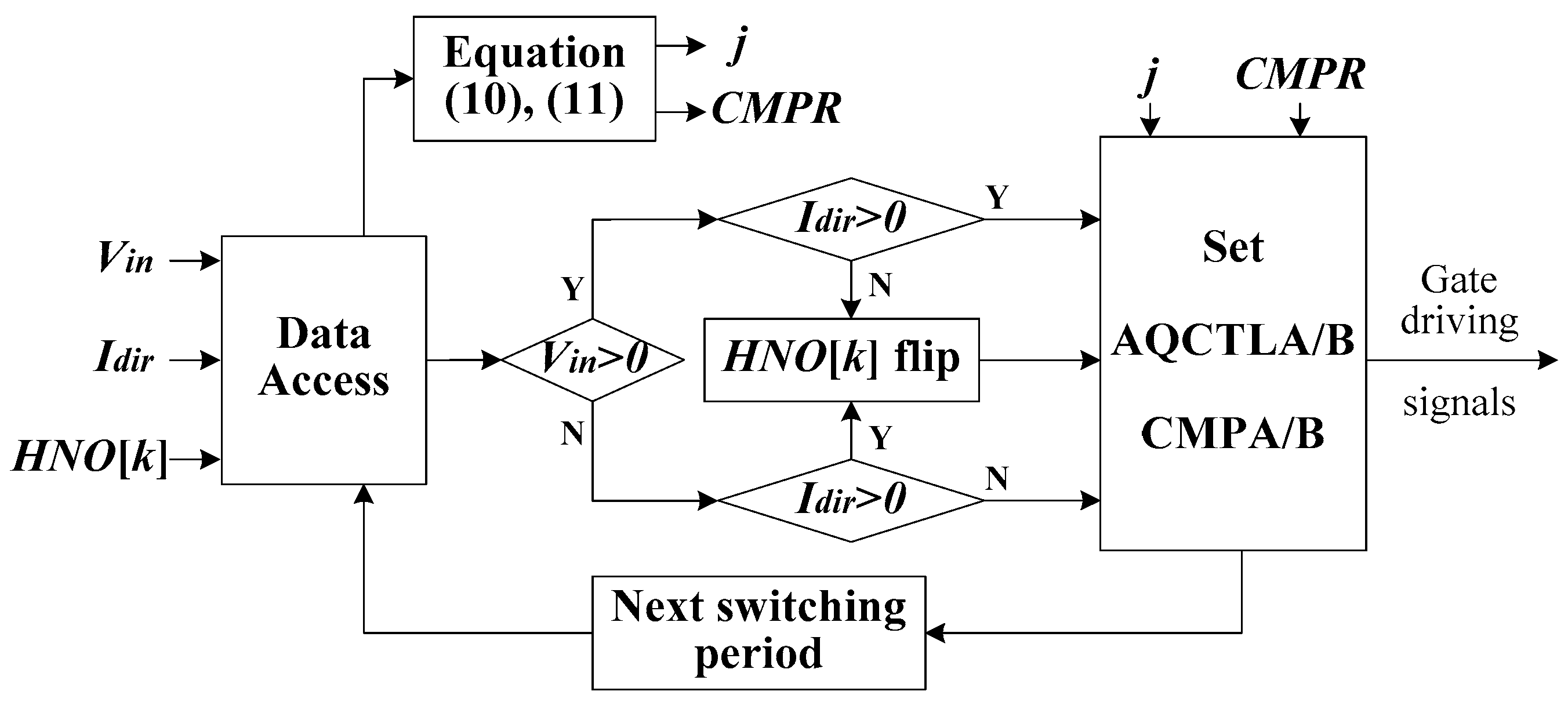
As analyzed above, the key to realizing the improved PD-PWM is to adjust the relative positions of the carrier waves for each power cell according to the magnitude of the DC-link voltages and the direction of input AC currents. Thus, the relative magnitude of the DC-link voltages should be known firstly. The flowchart of the DC-link voltage sorting function is depicted in
Figure 5. The DC-link voltage values are stored in the array
Vdc[
k] after being sampled and calculated through AD units. Then, the relative magnitude sequence of the DC-link voltages has been stored in the array
HNO[
k]. For example, if
Vdc3 < Vdc2 < Vdc1,
HNO[
k] will be equal to [2, 1, 0]; and if
Vdc1 < Vdc3 < Vdc2,
HNO[
k] will be equal to [0, 2, 1]. That is the higher the voltage is, the greater the number of the array
HNO[
k] member corresponding to the voltage.
The flowchart of implementation of the improved PD-PWM in DSP is shown in
Figure 6. The direction of the ac current
Idir is detected by a comparator with Schmitt-trigger characteristics.
Unlike analog PMW generator, the modulating wave is fabricated by an up-down counter in DSP and the counter value cannot be negative. Thus, it should be converted to positive when the modulating wave is in the negative half-cycle. In accordance with the symmetric PWM sampling theory, the value of time-base period (TBPRD) register for the PWM period counter in DSP is
where
fCLK is the PWM counter frequency,
fS is the carrier wave frequency.
When the improved PD-PWM works, only one H-bridge cell is under PWM control in any carrier wave cycle and the gate driving signals for switches in other H-bridge cells are at a constant high or low level. Assuming that the sinusoidal modulation signal is
Vin (−1 ≤
Vin ≤ 1), there is:
where “floor” is a rounding function, and
j represents the position of carrier waves which should be modulated. Considering
k = 3 as an example, when
j = 0, the H-bridge cell corresponding to the lowest position of carrier wave is under pulse width modulation; and when
j = 2, the H-bridge corresponding to the highest position of carrier wave is under modulation.
The corresponding value of compare register
CMPR for PWM is:
As stated earlier, the data stored in the array HNO[k] represent the relative magnitude of the DC-link voltages of the H-bridges. Similarly, the conditions of Vin > 0 and Idir > 0, or Vin < 0 and Idir < 0, also indicate the relative positions of the corresponding to carrier waves. Both of them should match to generate the correct PWM signals. For example, in such a case that Vdc1 < Vdc3 < Vdc2, the array HNO[k] is equal to [0, 2, 1], that is the carrier wave for the first H-bridge cell is placed at the bottom, and the carrier for the third H-bridge cell is in the middle position of other two carriers. However, at this moment, if Vin > 0 and Idir > 0, or Vin < 0 and Idir < 0, the data sequence stored in the array HNO[k] is opposite to the required position of the carrier waves. Thus, the value in the array HNO[k] should be flipped and rearranged.
Finally, the PWM modules corresponding to the H-bridge cells in DSP should be set according to the data in the array HNO[k]; then the required driving signals could be generated. The driving signals with fixed level (high or low) for switches in those H-bridge cells which are not in modulation could be acquired by configuring the Action-Qualifier Output A/B Control Register (AQCTLA/B) in the DSP.
5. Experimental Results
The validity of the proposed drive system is verified using the experimental results of the laboratory scale prototype. The prototype includes a nine-phase motor and its drive converter with nine power cells. The drive converter is constructed using IGBT-based intelligent power modules (IPMs) (Mitsubishi Electric Corp., Tokyo, Japan) and the related controller is implemented by DSP (TMS320F2812) (Texas Instruments Inc., Dallas, TX, USA). The developed nine-phase motor and the experimental platform are shown in
Figure 7. The input of the drive system is three-phase, and the nominal input AC line-to-line voltage is 380 V. The rated power is 10 kW. Other principal parameters of the prototype are given in
Table 3.
The first experiment investigates the steady-state performances of the proposed drive system.
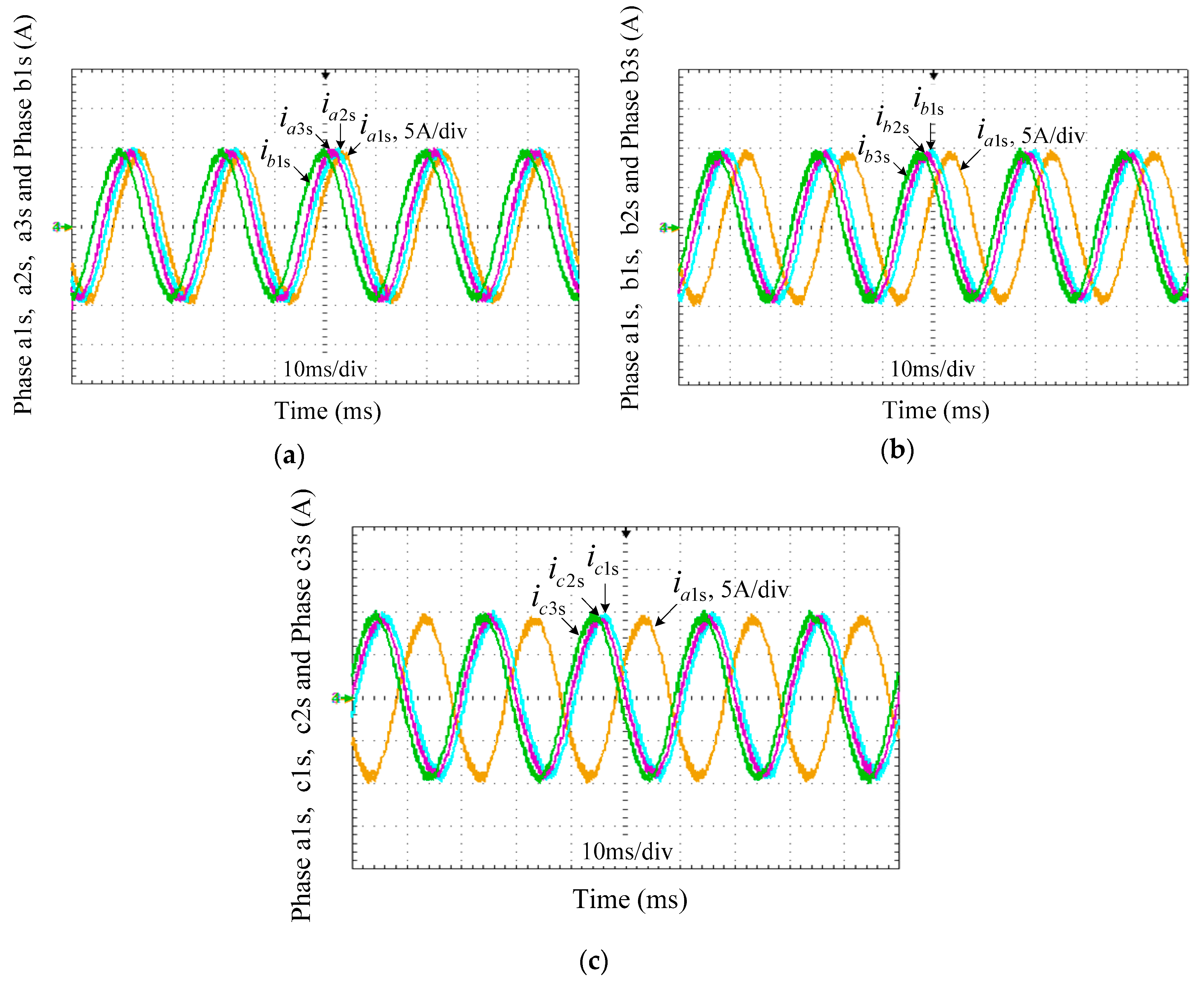
Figure 8 and
Figure 9 show the related waveforms. In
Figure 8, all phase currents of the stator are shown. The peak values of all stator currents are equal to about 10 A. The phase difference between adjacent stator windings is 20° because the nine stator windings of the motor are independent and uniformly distributed.
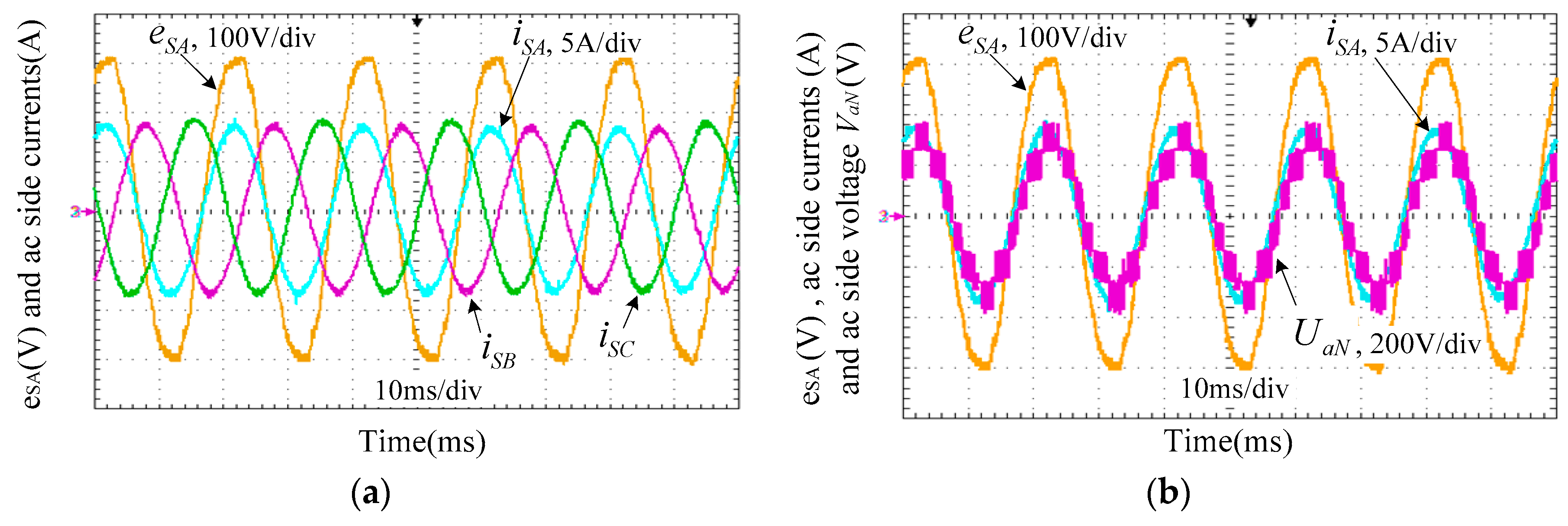
The steady-state voltage and current waveforms of the drive converter are shown in
Figure 9.
Figure 9a shows the line-side AC input voltage and currents. Although the input voltage
eSA is slightly distorted, which caused by the leakage inductance of the autotransformer, the three-phase input currents are virtually sinusoidal.
Figure 9b shows the line-side AC terminal phase voltage
UaN of the converter. There are seven levels in the phase voltage which meets the law of the cascaded H-bridge converter output voltage control.
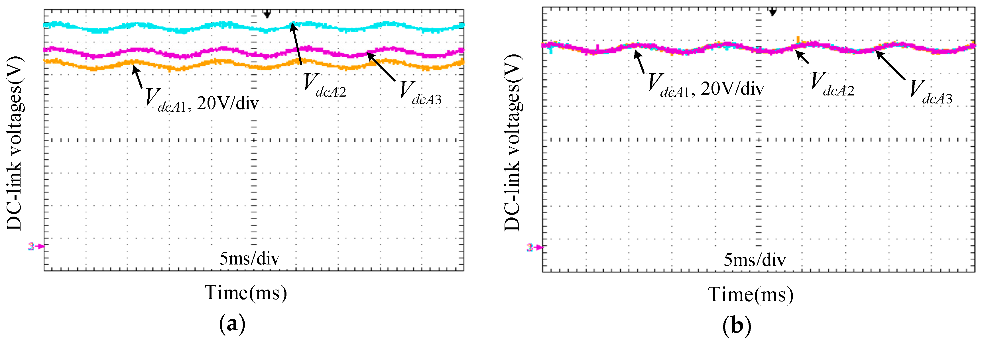
Figure 10 depicts the DC-link voltages of the phase A under different modulation conditions. As shown in
Figure 10a, the DC-link voltages have obvious imbalances among the three DC capacitors before the improved PD-PWM is carried out. Once the proposed improved PD-PWM for DC-link voltage balancing is implemented, the three DC-link voltages maintain a satisfying consistency, as shown in
Figure 10b.
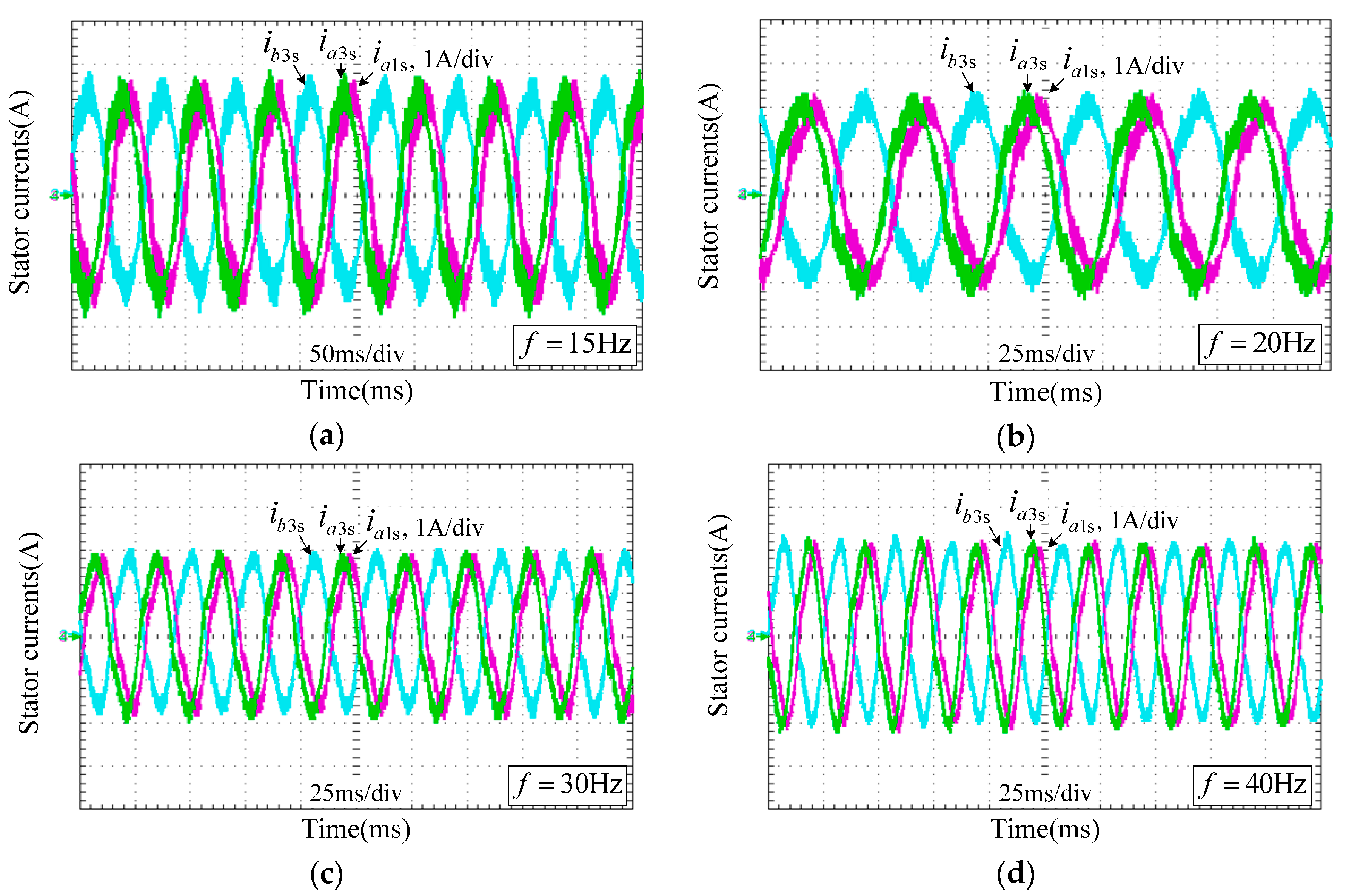
Figure 11 shows the waveforms when the multiphase motor starts at variant frequencies without mechanical load. The initial frequency of the startup is 5 Hz. The stator winding current waveforms under different frequencies during the startup process are depicted. As shown, during the startup process, the frequency of the stator currents of the motor varies slowly as desired. The magnitudes of these currents vary slightly during the entire startup process due to no load. The entire startup process is smooth. There are harmonics in the currents at low frequencies. The reason is that the modulation indexes of the inverters are quite small at low frequency since the V/f control is used.


