Article

Multi-Objective Predictive Balancing Control of Battery Packs Based on Predictive Current

1
New Energy Research Center, School of Electric Power, South China University of Technology, Guangzhou 510640, China
2
Guangdong Key Laboratory of Clean Energy Technology, School of Electric Power, South China University of Technology, Guangzhou 510640, China
3
College of Electrical Engineering and Automation, Henan Polytechnic University, Jiaozuo 454000, China
*
Author to whom correspondence should be addressed.
Energies 2016, 9(4), 298; https://doi.org/10.3390/en9040298
Submission received: 12 November 2015 / Revised: 21 March 2016 / Accepted: 23 March 2016 / Published: 19 April 2016

Abstract

:
Various balancing topology and control methods have been proposed for the inconsistency problem of battery packs. However, these strategies only focus on a single objective, ignore the mutual interaction among various factors and are only based on the external performance of the battery pack inconsistency, such as voltage balancing and state of charge (SOC) balancing. To solve these problems, multi-objective predictive balancing control (MOPBC) based on predictive current is proposed in this paper, namely, in the driving process of an electric vehicle, using predictive control to predict the battery pack output current the next time. Based on this information, the impact of the battery pack temperature caused by the output current can be obtained. Then, the influence is added to the battery pack balancing control, which makes the present degradation, temperature, and SOC imbalance achieve balance automatically due to the change of the output current the next moment. According to MOPBC, the simulation model of the balancing circuit is built with four cells in Matlab/Simulink. The simulation results show that MOPBC is not only better than the other traditional balancing control strategies but also reduces the energy loss in the balancing process.

1. Introduction

Currently, due to the continuous deterioration of air quality and the lack of oil resources, new electric vehicles with low emission and low fuel consumption have become the focus of major automobile companies [1]. The battery pack, as a critical component of electric vehicles, has a significant impact on dynamic performance, economy, and safety.
Because single cells have limited capacity and relatively low voltage, battery packs are generally composed of a plurality of single cells in series and parallel compositions to meet the requirements of electric vehicles. As a result, due to the inevitable inconsistency problem in the application of the same type of cell, the life of a battery pack is seriously affected, and overcharge and over-discharge phenomena are caused [2]. To reduce the battery pack inconsistency, to prolong the life of battery pack, to improve the overall performance of the battery pack, and to ensure the safety and reliability of the battery pack, balancing control needs to be adopted. Although there are many balancing control methods for battery packs, they ignore the degradation and temperature conditions of the battery pack, causing differences between cells to increase [3,4,5,6,7,8,9,10,11,12,13,14].
To solve this problem, the multi-objective predictive balancing control (MOPBC) of battery packs based on predictive current is proposed. The working principle is to make the inconsistency of battery packs under different driving conditions automatically tend to be consistent in the forecast period, on the condition that the required output current of the battery pack has been obtained, combined with multi-objective balancing control to achieve degradation balancing, state of charge (SOC) balancing, and temperature balancing simultaneously. Due to the different internal resistance of each cell, the heat generated will be different, and different temperatures will cause different degradation rates of each cell. Finally, the differences between each cell will gradually increase. In the case that the future output current of the battery pack has been predicted, the temperature and ageing differences between each cell can be obtained, and the differences can be added into the present multi-objective balancing control. Then, the present differences of the SOC, temperature, and degradation rate in the forecast period can be compensated, making the battery pack reach a balance. The proposed MOPBC effectively achieves battery pack balancing and prolongs the life of a battery pack but also reduces the energy loss in the process of balancing through reducing the required balancing times and balancing current. To verify the effectiveness and superiority of the proposed MOPBC, a simulation model of the balancing circuit is built in Matlab/Simulink (Natick, MA, USA) with four cells. The simulation results show that the proposed control strategy utilizes the future output current changes effectively and makes the control effect better than other balancing controls.
The rest of this paper is organized as follows. In Section 2, the predictive current control is introduced. Section 3 analyzes the causes of inconsistency of the battery pack and balancing method. The battery model and the derivation process of the formulas of MOPBC are introduced in Section 4. In Section 5, by comparing with non-balancing, SOC balancing and multi-objective balancing, the effectiveness and reasonableness of the proposed control strategy are demonstrated. Finally, the conclusions are summarized in Section 6.

2. Predictive Current Control

The output current change of the battery pack is a continuous process in the driving process of an electric vehicle, so the changing direction of the output current curve can be predicted by analyzing the changing trend of the output current. The principle is as follows: supposing the battery pack output current is Ip2 at time (k − 2)t, the battery pack output current is Ip1 at time (k − 1)t, and the battery pack output current is Ic at the time kt, thus at the next time, namely at time (k + 1)t, the battery pack output current Il is:
I l = t × ( I c I p 1 t + I c I p 1 t I p 1 I p 2 t ) = 2 I c 3 I p 1 + I p 2
To further improve the prediction accuracy, we can increase the number of known currents or reduce the prediction time interval.
Compared with conventional control strategies, due to adding the predictive control, the predictive balancing control of the battery pack not only considers the present electric vehicle driving requirements and state information but also includes the change information of the future current.

3. Balancing Control Strategy

3.1. The Analysis of Battery Pack Inconsistency

There are two substantial and inevitable reasons for battery pack inconsistency, namely, manufacturing technology and degradation rate. In the manufacturing process, technical and material differences cause variation in batches of cells belonging to the same type with respect to capacity, internal resistance, and some other parameters. When there are capacity differences in the charging process, cells of small capacity will be fully charged first, while the battery pack charging process is not finished, and then the overcharging phenomenon will occur. In the discharging process, most of the cells are still in a shallow discharging condition, but cells of small capacity have already been in a deep discharging condition, leading to over-discharging. When there are internal resistance differences, the generated heat and the discharging depth of the cells will be different. In turn, these differences will also affect the internal resistance. With the discharging depth of cells continuing to deepen, the higher the temperature is, the smaller the internal resistance is, and the lower the temperature is, the larger the internal resistance is. A cell with local high temperature will decay faster than other cells. Long-running will damage the consistency of the battery pack, leading to a decline of the battery performance and shortening the life [15]. The coupling relationship between these internal and external factors that affect battery pack inconsistency is shown in Figure 1. In summary, the original inconsistency problem between the same type of cells, combined with the cell charging and discharging rate, depth of discharging, ambient temperature, and other external factors, will lead to cell degradation at different rates. Finally, as the differences between cells are increase, the battery pack fails prematurely.

3.2. Battery Pack Balancing Method

Due to the differences between cells caused by the manufacturing process, battery pack consistency is enhanced by improving the technological level before the cells leave the factory, as well as by classifying the cells that are going to be gathered in the same group [16]. However, initial performance differences of cells existing in the battery pack application and can only be diminished. Although single-cell technology has made major breakthroughs and its performance has improved significantly, ensuring the consistency of the initial performance of cells, the battery pack will also produce differences because of the working conditions and the environment. The key factor affecting the life of the battery pack is to maintain consistency, not the initial differences of the cells. Therefore, to further improve the consistency of the battery pack during the working process, it is necessary to use balancing control.
Several balancing control strategies have been proposed, such as voltage balancing, SOC balancing, and capacity balancing.

3.2.1. Voltage Balancing

Voltage balancing depends on the voltage of each cell or the average voltage for the balancing operation, making the voltage of each cell consistent by charging and discharging with a balancing circuit. Although voltage balancing can solve the problem of voltage imbalance of the battery pack, battery pack performance cannot be evaluated only by its voltage level. When a cell of low capacity is in charging or after it finishes charging, its terminal voltage may be higher than other cells. If this balancing method is used, the balancing result is that cells of low capacity add energy to cells of high capacity, which increases the capacity differences between each cell in the battery pack.

3.2.2. SOC Balancing
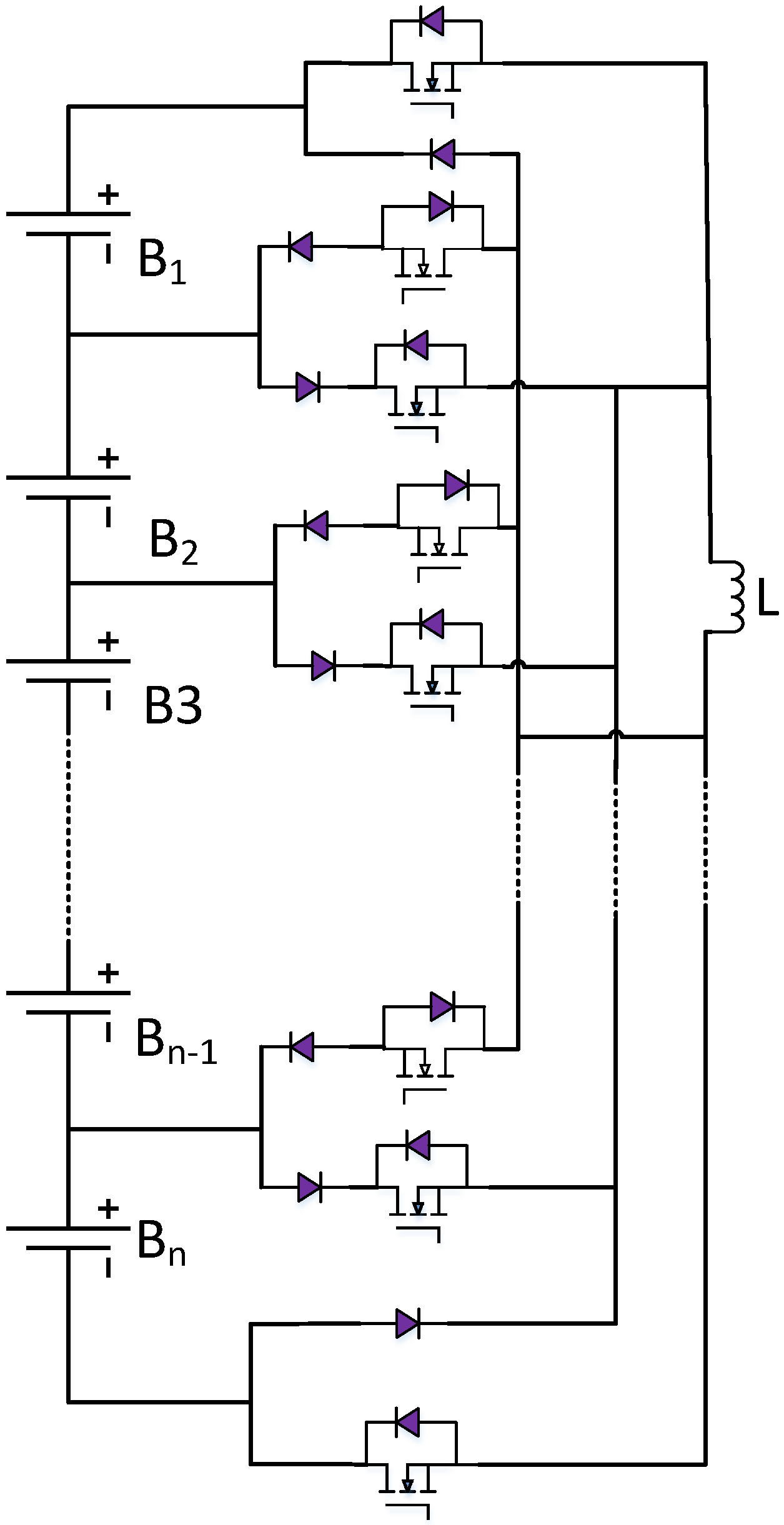
SOC balancing adjusts the cell charging and discharging rates based only on the SOC of each cell or their average value, which will only solve the problem of performance degradation for cells with larger capacity in the battery pack due to insufficient charging. However, SOC balancing cannot reduce or eliminate the differences between the actual capacities of each cell [17].

3.2.3. MOPBC

These control methods only focus on a single objective, without considering the mutual influence among various factors, and are only based on external performance parameters, which is not sufficient, and the function of the balancing circuit is also more than these factors. To solve the above problems, this paper selects SOC, temperature, and degradation rate as the balancing control objectives from the internal and external factors affecting the inconsistency of battery packs. First, SOC balancing can make the most of battery pack performance. Moreover, temperature balancing and degradation rate balancing can prolong the battery pack life and further avoid producing inconsistency in the battery pack. In the balancing process, because the current has been obtained by predictive current control in the forecast period, we can calculate the future heat differences according to the different internal resistance of each cell. These heat differences are used as the present temperature compensation, which means there is no need to the address present temperature imbalance or to balance part of it, and the rest is compensated by the heat generated in the forecast period. Finally, the control strategy accomplishes multi-objective balancing, improves the consistency of the battery pack, and prolongs battery pack life.

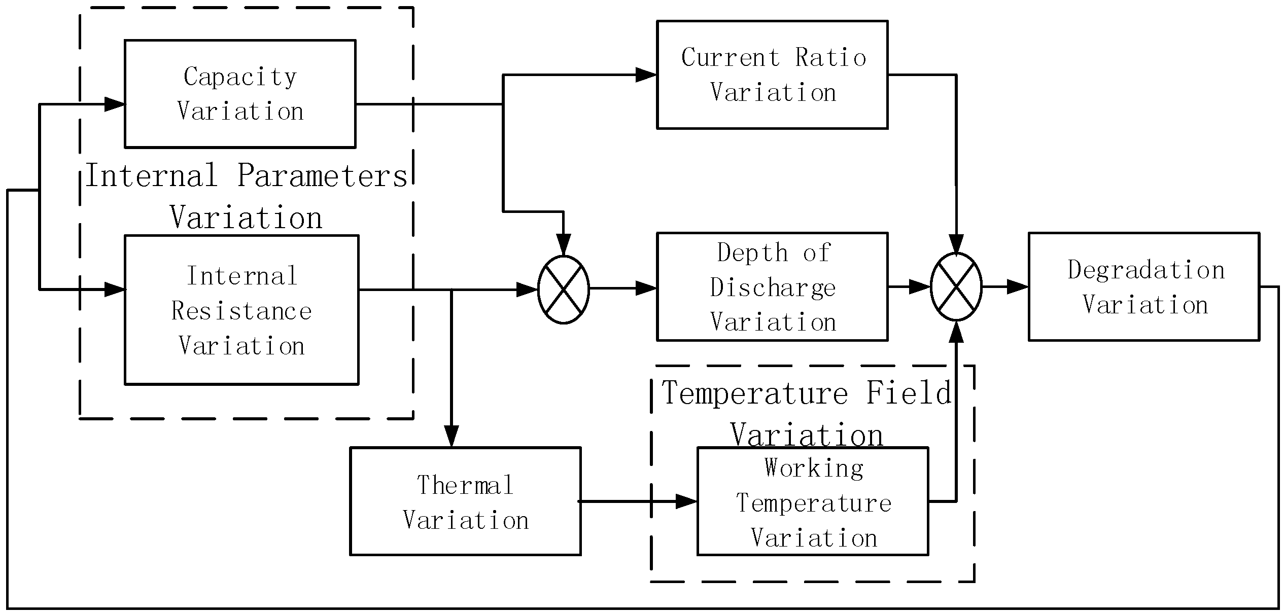
4. Battery Pack Balancing Control Modelling

To verify the validity and feasibility of the proposed strategy, the battery model is established according to the coupling relationship between the internal and external factors of cells. The model contains four modules. They are battery parameters, degradation, temperature, and SOC, respectively.

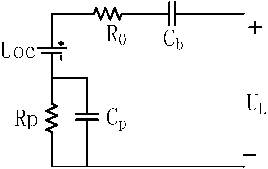
4.1. Battery Parameters Module

Several battery equivalent circuit models have been proposed, including the Rint model, Thevenin model, RQ model (It is composed of resistance R and constant phase angle element Q), DP (Double Polarization) model, and PNGV (partnership for a new generation of vehicles) model. The PNGV model is a low order model, but compared with the Thevenin model and Rint model, it has a higher accuracy and can better describe the transient response process of the battery [7,18]. Compared with DP, RQ, and other higher order circuit models, PNGV has the characteristics of a simple model and easy parameter identification. In this article, a PNGV model is established according to the parameter look-up table method, as shown in Figure 2.

4.2. SOC Module

The ampere-hour counting method is a relatively common, simple, and reliable method for estimating the SOC. When the discharge current is positive and the charging current is negative, the calculation formula can be expressed as:
SOC = S O C i n i t 1 C E 0 t η i ( t ) d t
where SOCinit is the initial value of SOC, CE is the battery capacity, and η is the coulomb efficiency.

4.3. Temperature Module

As mentioned in [18], battery temperature change is determined by the heat generated by the internal resistance and heat exchange with the ambient environment. The heat conservation equation can be written as follows:
m · c p · d T ( t ) d t = i ( t ) 2 · R h c S [ T ( t ) T a ]
where m is the battery mass, cp is the specific heat of the cell, Ta is the ambient temperature, hc is the battery heat transfer coefficient, R is the battery internal resistance, and S is the battery external surface area.

4.4. Degradation Module

According to the accelerated degradation experimental data, based on the mechanism of the temperature T effect on battery degradation, we can determine the degradation rate ε c [19]:
ε c = e 4218.61 × ( 1 298 1 T )
Considering small changes of the degradation rate d ε c , we can obtain the differential Equation (5):
d ε c = 4218.61 × 1 T 2 × e 4218.61 × ( 1 298 1 T )
According to the relationship between the degradation rate and the impedance decay rate ε r , we can obtain Formula (6):
ε r = 2.21 ε c 1.12

4.5. MOPBC

To achieve better balancing control, a balancing circuit with perfect performance is essential. Several balancing topologies have been proposed. Based on the comparison of the various topologies in [3], the topology of active equalization is chosen in this paper, as shown in Figure 3, to perform the balancing control strategy verification. The circuit only requires one inductor; can balance bi-directionally due to each cell having its own charging and discharging circuit; and has the advantages of high-speed balancing, low cost, and small size.
In the balancing model constructed according to Figure 3, input parameters are the initial battery SOC, capacity and battery pack output current, the output is a switch combination option of the balancing circuit in the charge state, discharge state, or suspended state. N sections of cells denoted as B1, B2,······,Bn, compose a battery pack. The corresponding battery degradation rate is denoted as ε c 1 , , ε c 2 ,······, ε c n . The minimum value is denoted as ε c m i n . SOC is denoted as p1, p2,······, pn. The minimum value is denoted as p min . Temperature at the present time is denoted as T1, T2,······, Tn. The minimum value is denoted as T min . Using the formula P = I2R and current prediction, the heat generated at time (k + 1)t can be obtained and is denoted as f1, f2,······, fn. The minimum value is denoted as fmin. Equations (7)–(10), respectively, describe the imbalance degree of the degradation rate, SOC, temperature, and future heat of each cell.
D ( ε c i ) = ε c i ε c m i n
D ( p i ) = p i p min
D ( T i ) = T i T min
D ( f i ) = f i f min
where i = 1, 2,······n. D ( ε c i ) ,   D ( p i ) , D ( T i ) , and D ( f i ) form an n-dimensional vector X closely related to the current. Therefore, the battery pack balancing problem will be transformed into a certain calculation of vector X, which makes the initial state vector X be transformed to the target state vector. Under certain constraint conditions, the target state vector obtains the required value by finding an optimal path. The optimal path determines the transfer of the balancing current from one cell to another.
To make D ( ε c i ) ,   D ( p i ) , and D ( T i ) have the same order of magnitude and make a trade-off between the three parameters, the weights W ε , W p , and W T need to be separately added, and W ε + W p + W T = 1 . Coefficient W f also needs to be added to the coming heat imbalance degree to compensate the present temperature imbalance degree. The coefficient W f is inversely related to the forecast period, namely, the longer the forecast period is, the smaller the coefficient W f is, and the smaller the effect of coming heat on temperature is. Conversely, the shorter the forecast period is, the bigger the coefficient W f is, and the greater the effect of the coming heat on temperature is. Finally, the total imbalance degree of each cell is:
D i = 0 T ( W ε D ( ε c i ) + W p D ( p i ) W T ( D ( T i ) + W f D ( f i ) ) ) d t
where T is the charging and discharging time. To obtain the maximum value Dmax and the minimum value Dmin of Di, namely, the global optimal solution that can be obtained by convex optimization, the constraint conditions are:
I b a l m i n I i b a l ( t ) I b a l m a x
i = 1 n I ibal ( t ) = 0
I i b ( t ) = I i c ( t ) + I i b a l ( t )
where I i b a l ( t ) is the balancing current of cell Bi (i = 1, 2,······, n) at moment t, I b a l m i n is the minimum balancing current, I b a l m a x is the maximum balancing current, I i c ( t ) is the battery charging and discharging current, and I i b ( t ) is the total current flowing through the battery Bi. Finally, the switch combination option can be obtained, as shown in Equation (14).
s i g n i = { 1   D i D m a x 0 0 D m i n D i D m a x   ( i = 1 , 2 , , n ) 1   D i D m i n 0
where signi = 1 means that cell Bi provides balancing energy, i.e., controlling the switch to conduct battery discharge circuit of Bi to the charge inductor in Figure 5; signi = 0 means that cell Bi does not perform other processing; signi = −1 means that cell Bi absorbs balancing energy, which controls the switch to conduct the battery charging circuit of Bi to make the inductor charge the cell. To guarantee that the inductor current in a switch cycle can drop to zero, considering the safety margin, the inductor needs to work in DCM (discontinuous conduction mode). The inductor current expression is as follows:
i L = { V i s L t 0 t < D s T s V i s L D s T s V i r L ( t D s T s ) D s T s t < T z 0 T z t T s
where L is the inductance value, i L is the inductor current, D s is the switch duty ratio, T s is the switch cycle, T z is the moment the inductive current drops to zero, V i s is the sum of voltages of the cells that provide balancing energy, and V i r is the sum of voltages of the cells that absorb balancing energy. Because T s is larger than T z , when t = T s :
V i s L D s T s V i r L ( T s D s T s ) < 0
That is:
D s < V i r V i s + V i r

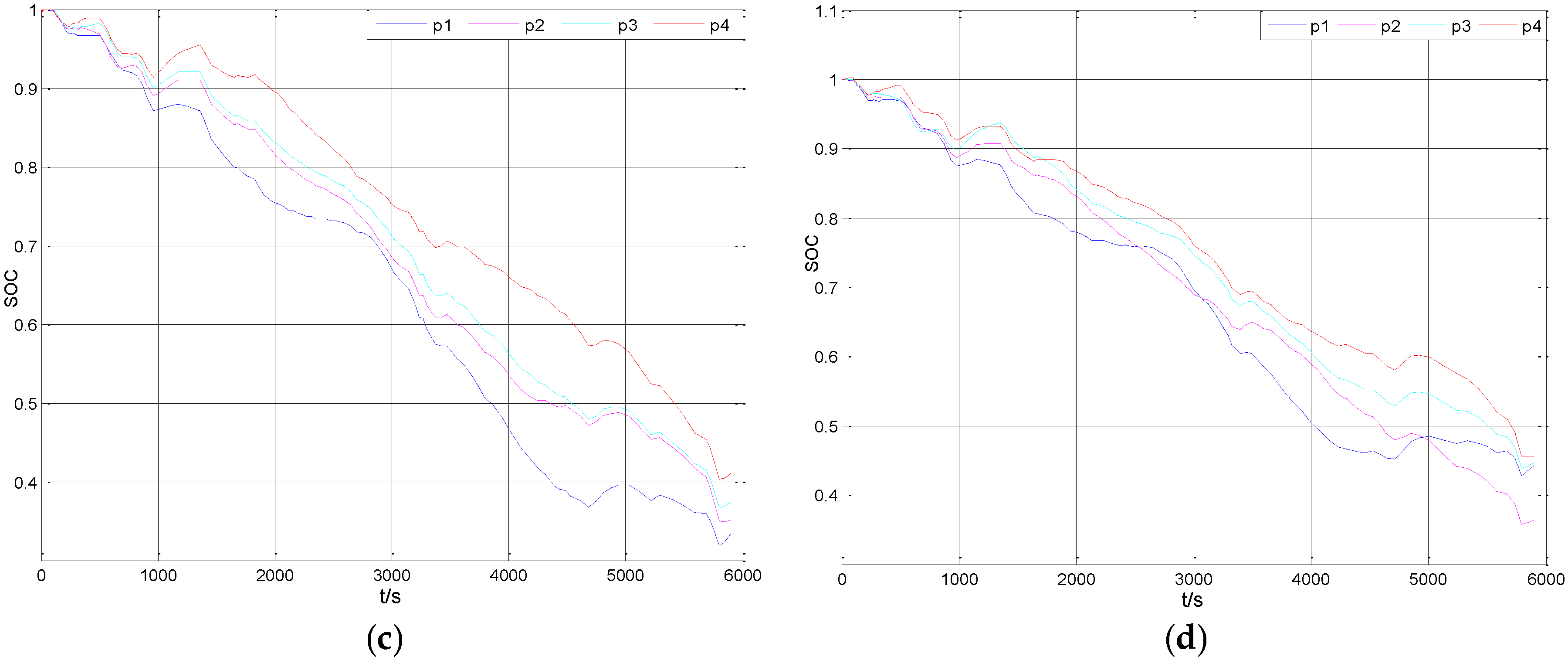
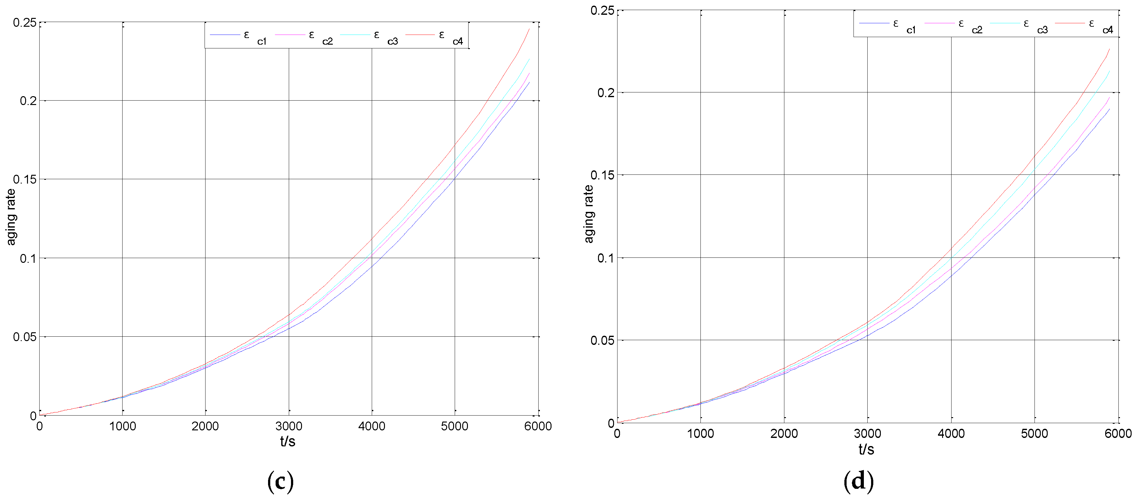
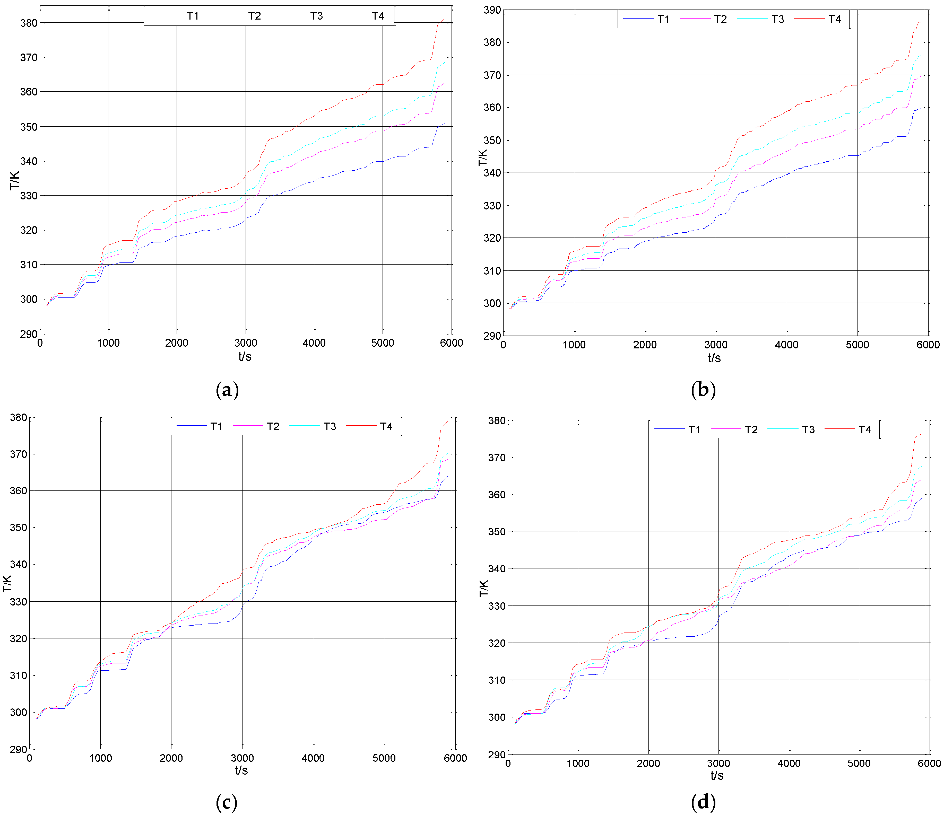
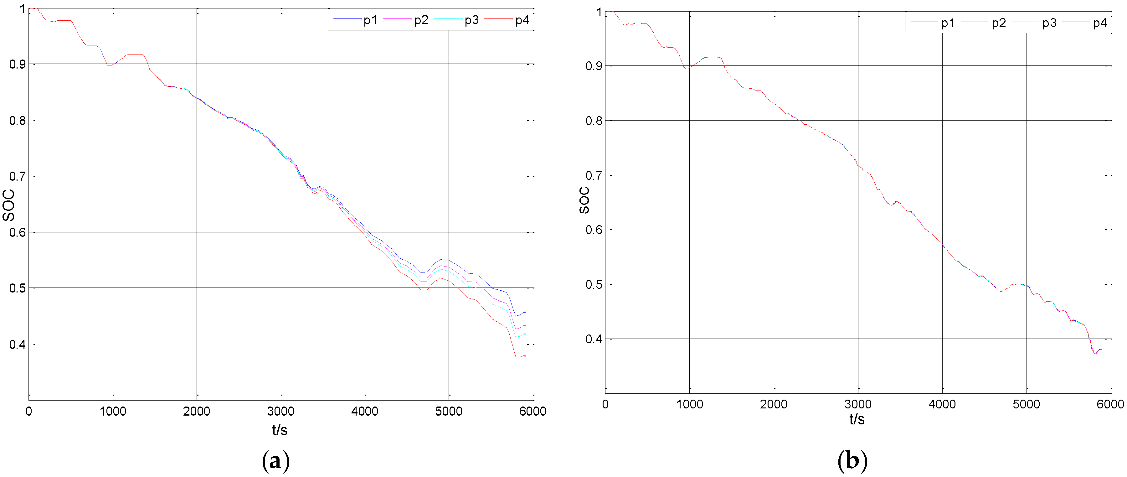
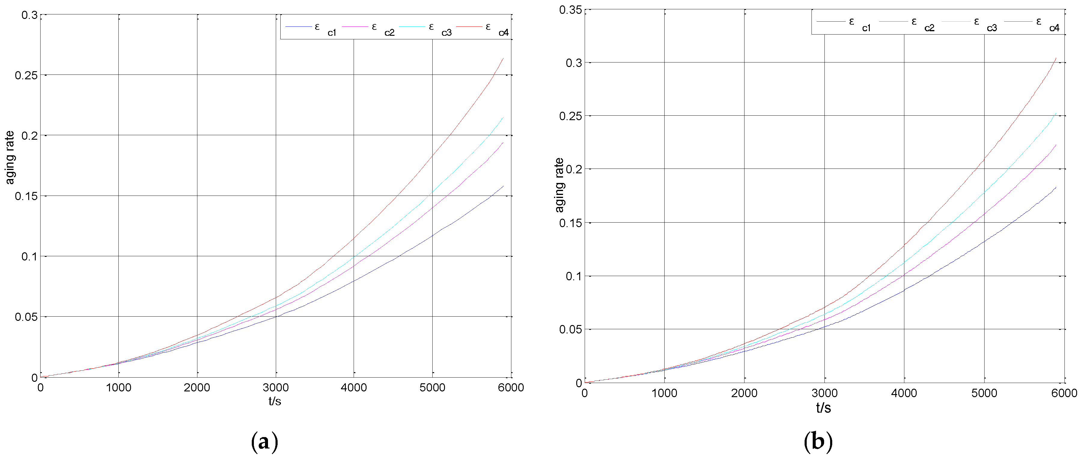
5. The Analysis of the Simulation Results

To validate the balancing effect of the proposed control strategy, four sections of a lithium battery in series are selected. The simulation parameters of the battery pack are shown in Table 1. The output current of the battery pack is the input of the simulation. Figure 4a–d are the simulation results of SOC under conditions of non-balancing, SOC balancing, multi-objective balancing, and MOPBC, respectively.
Figure 5a–d are the simulation results of the degradation rate under conditions of non-balancing, SOC balancing, multi-objective balancing and MOPBC, respectively.
Figure 6a–d are the simulation results of temperature under conditions of non-balancing, SOC balancing, multi-objective balancing and MOPBC, respectively.
Table 2 shows the results of various methods at the final moment. The max column represents the difference between the maximum and the minimum value. ave column indicates the average value.
From the max comparison (0.0778 and 0.0011) of SOC between non-balancing and SOC balancing control, it can be observed that SOC is consistent and the max of SOC is reduced to a negligible degree after adding SOC balancing control. However, from the ave comparison (0.4218 and 0.3791) of SOC, it can be observed that the capacity consumption of each cell has increased because the effects of temperature and degradation on the battery are not considered in the balancing process. Merely pursuing SOC balancing will make B4 also provide balancing current. When the current flowing through B4 increases because of its internal resistance of 1.5 mΩ, as shown in Table 1, it is the biggest and according to P = I2R, it will generate more heat, making the temperature increase faster compared with other cells. The higher the temperature is, the faster the battery degradation rate is, resulting in an increase of internal resistance. After the internal resistance increases, the battery capacity consumption increases more and the SOC decreases more rapidly. However, to balance SOC, other cells need to provide more balancing current, generating more heat, which also leads to a larger ave (372.748 K and 0.2407) of the temperature and the degradation rate.
From the results comparison between multi-objective balancing and the former two control strategies, it can be observed that to ensure the whole cell performance in the multi-objective balancing control, the other cells provide more balancing current to B4 and reduce the situation that B4 outputs balancing current, so B1 (0.3330), B2 (0.3510), and B3 (0.3740) consume more energy and the ave (0.3669) of SOC decreases slightly. Moreover, the consumed energy of B4 (0.4097) decreases greatly, so max (0.0767) of SOC does not change. However, from the temperature (378.822 K) and degradation rate (0.2454) of B4, it can be observed that the maximum temperature and degradation rate in the whole cell are reduced, which prolongs the battery pack life and greatly improves the consistency of the temperature and degradation rate. From here, we can see that making a trade-off in the SOC balancing achieves balancing and improvement of the temperature and degradation rate. Thus, to a certain extent, SOC balancing, temperature balancing, and degradation balancing are achieved simultaneously.
Finally, from the results comparison between MOPBC and the former three control strategies, it can be observed that MOPBC balances the present temperature by using the coming heat difference generated in the forecast period, which greatly reduces energy consumption and the situation that each cell provides balancing current, and the ave (0.4272) of SOC is increased. Although making a trade-off in the SOC balancing does not decrease the max (0.0915) of SOC, it greatly reduces the maximum temperature (376.182 K) and degradation rate (0.2265) and their ave (366.646 K and 0.2066) compared with other balancing methods. Therefore, MOPBC reduces the energy consumption in the balancing process, greatly improves the battery pack performance, and further prolongs the battery pack life.

6. Conclusions

On the condition that the required output current of the battery pack has been obtained by predictive current control, the proposed MOPBC of a battery pack based on the predictive current in this paper makes the inconsistency of the battery pack under different driving conditions automatically tend to be consistent in the forecast period, combined with multi-objective balancing control that achieves degradation balancing, SOC balancing, and temperature balancing simultaneously. This method achieves battery pack balancing, prolongs the life of the battery pack, and reduces the energy loss in the balancing process. The simulation results show that this control strategy effectively utilizes the future output current changes and improves the control effect compared to SOC balancing and multi-objective balancing control. The discussions and results indicated that the proposed method is effective and feasible.

Acknowledgments

This work is supported by the DongGuan Innovative Research Team Program (No. 201460711900131) and the National Natural Science Foundation of China (Grant No. 51377058). I would like to express my deepest gratitude to my supervisor, Longyun Kang, who has provided me with valuable guidance at every stage of this paper-writing. I would also like to thank the anonymous reviewers for dedicating the time to review my paper despite their busy schedules.

Author Contributions

This research article has five authors. The circuit structure was designed by Wenbiao Li and Longyun Kang. Wenbiao Li and Longyun Kang conceived the research methods and control strategies. Wenbiao Li, Xiangwei Guo, and Yuan Yao designed and performed the experiments. Longyun Kang contributed the experimental environment. Wenbiao Li wrote the paper.

Conflicts of Interest

The authors declare no conflicts of interest.

References

  1. Deng, Y.D.; Gao, H.O.; Wang, Z.F. Control strategies of parallel hybrid electric vehicle. J. Eng. J. Wuhan Univ. 2004, 37, 139–144. [Google Scholar]
  2. Cassani, P.A.; Williamson, S.S. Significance of Battery Cell Equalization and Monitoring for Practical Commercialization of Plug-In Hybrid Electric Vehicles. In Proceedings of the Applied Power Electronics Conference and Exposition, Washington, DC, USA, 15–19 February 2009; pp. 465–471.
  3. Daowd, M.; Omar, N.; Bossche, P.V.D.; Van Mierlo, J. A Review of Passive and Active Battery Balancing Based on MATLAB/Simulink. J. Int. Rev. Electr. Eng. 2011, 6, 2974–2989. [Google Scholar]
  4. Zhang, D.H.; Zhu, G.R.; He, S.J.; Qiu, S.; Ma, Y.; Wu, Q.-M.; Chen, W. Balancing Control Strategy for Li-Ion Batteries String Based on Dynamic Balanced Point. Energies 2013, 8, 1–5. [Google Scholar]
  5. Huang, W.; Abu, Q.J. Energy Sharing Control Scheme for State-of-Charge Balancing of Distributed Battery Energy Storage System. J. IEEE Trans. Ind. Electron. 2015, 62, 2764–2776. [Google Scholar] [CrossRef]
  6. Kandasamy, K.; Vilathgamuwa, D.M.; Tseng, K.J. Double star chopper cell converter for battery electric vehicles with inter-module SoC balancing and fault tolerant control. In Proceedings of the Industrial Electronics Society, Dallas, TX, USA, 29 October 2014–1 November 2014; pp. 2991–2996.
  7. Kim, J.H.; Shin, J.W.; Jeon, C.Y.; Cho, B.H. Screening process of Li-Ion series battery pack for improved voltage/SOC balancing. In Proceedings of the Power Electronics Conference (IPEC), Sapporo, Japan, 21–24 June 2010; pp. 1174–1179.
  8. Maharjan, L.; Inoue, S.; Akagi, H.; Asakura, J. State-of-Charge (SOC)-Balancing Control of a Battery Energy Storage System Based on a Cascade PWM Converter. J. IEEE Trans. Power Electron. 2009, 24, 1628–1636. [Google Scholar] [CrossRef]
  9. Bonfiglio, C.; Roessler, W. A Cost Optimized Battery Management System with Active Cell Balancing for Lithium Ion Battery Stacks. In Proceedings of Vehicle Power and Propulsion Conference, Dearborn, MI, USA, 7–10 September 2009; pp. 304–309.
  10. Danielson, C.; Borrelli, F.; Oliver, D.; Anderson, D.; Kuang, M.; Phillips, T. Balancing of battery networks via constrained optimal control. In Proceedings of the American Control Conference (ACC), Montreal, QC, Canada, 27–29 June 2012; pp. 4293–4298.
  11. Sun, C.; Moura, S.J.; Hu, X.; Hedrick, J.K.; Sun, F. Dynamic Traffic Feedback Data Enabled Energy Management in Plug-in Hybrid Electric Vehicles. J. Control Syst. Technol. 2015, 23, 1075–1086. [Google Scholar]
  12. He, Y.; Rios, J.; Chowdhury, M.; Bhavsar, P. Forward power-train energy management modeling for assessing benefits of integrating predictive traffic data into plug-in-hybrid electric vehicles. J. Transp. Res. D Trans. Environ. 2012, 17, 201–207. [Google Scholar] [CrossRef]
  13. Sun, C.; Hu, X.; Moura, S.J.; Sun, F. Velocity Predictors for Predictive Energy Management in Hybrid Electric Vehicles. J. IEEE Trans. Control Syst. Technol. 2015, 23, 1197–1204. [Google Scholar]
  14. Shu, H.; Gao, Y.P.; Yang, W.; Jiang, Y. Study on Predictive Control of Fuel Economy for Medium HEVs. J. Highw. Transp. Res. Dev. 2009, 26, 149–153. [Google Scholar]
  15. Li, N.; Bai, K.; Chen, H.; Liu, P.; Niu, H. Summary of Equalization for LiFePO4 Li-ion Batteries. J. North China Electr. Power 2012, 2, 60–65. [Google Scholar]
  16. Wang, Z.P.; Sun, F.C.; Lin, C. An Analysis on the Influence of Inconsistencies upon the Service Life of Power Battery Packs. J. Trans. Beijing Inst. Technol. 2006, 26, 577–580. [Google Scholar]
  17. Ma, Y.L.; Chen, Q.S. Research on the Inequality of Lead Acid Batteries and Equalizing Charge. J. Wuhan Unive. Sci. Technol. (Nat. Sci. Ed.). 2001, 24, 48–51. [Google Scholar]
  18. Gao, L.J.; Liu, S.Y.; Dougal, R.A. Dynamic Lithium-Ion Battery Model For System Simulation. IEEE Trans. J. Compon. Packag. Technol. 2002, 25, 495–505. [Google Scholar]
  19. Tian, H.L. Modeling of Capacity Decline and Research of Performance Prediction of Lithium-Ion Battery Pack. Master’s Thesis, Beijing Institute of Technology, Beijing, China, 2015. [Google Scholar]
Figure 1. The coupling relationship between the internal and external factors.
Energies 09 00298 g001
Figure 2. Partnership for a new generation of vehicles (PNGV) model.
Energies 09 00298 g002
Figure 3. Balancing topology.
Energies 09 00298 g003
Figure 4. The results of state of charge (SOC) under different balancing control conditions. (a) Non-balancing control; (b) SOC balancing control; (c) Multi-objective balancing control; (d) Multi-objective predictive balancing control (MOPBC).
Energies 09 00298 g004aEnergies 09 00298 g004b
Figure 5. The results of the degradation rate under different balancing control conditions. (a) Non-balancing control; (b) SOC balancing control; (c) Multi-objective balancing control; (d) MOPBC.
Energies 09 00298 g005aEnergies 09 00298 g005b
Figure 6. The results of the temperature under different balancing control conditions. (a) Non-balancing control; (b) SOC balancing control; (c) Multi-objective balancing control; (d) MOPBC.
Energies 09 00298 g006
Table 1. Simulation parameters.
VariableSymbolValueUnit
Rated voltageVb3.7V
Rated capacityCE10Ah
Initial SOCSOCinit1, 1, 1, 1-
Initial resistanceR1, 1.2, 1.3, 1.5m Ω
The average balancing currentIave1.8A
Switching frequencyfs10kHz
Battery massm1.2Kg
Specific heatcp0.9J/(kg·K)
External surface areaS0.046m2
Ambient temperatureTa298K
Balancing weight W ε ,   W p , W T 0.8410, 0.0118, 0.1472-
Coulombic efficiencyη1-
Compensation coefficient W f   1-
Forecast periodtf0.5s
Table 2. The simulation results comparison.
Non-BalancingB1B2B3B4maxave
SOC0.45720.43290.41780.37940.07780.4218
Temperature (K)350.790362.427368.469381.10130.311365.697
Degradation Rate0.15760.19370.21460.26330.10570.2037
SOC BalancingB1B2B3B4maxave
SOC0.37980.37870.37900.37870.00110.3791
Temperature (K)359.583369.408375.760386.23926.656372.748
Degradation Rate0.18310.22290.25270.30400.12090.2407
Multi-Objective BalancingB1B2B3B4maxave
SOC0.33300.35100.37400.40970.07670.3669
Temperature (K)363.989368.350370.136378.82214.833370.324
Degradation Rate0.21160.21720.22640.24540.03380.2252
MOPBCB1B2B3B4maxave
SOC0.44300.36400.44630.45550.09150.4272
Temperature (K)358.974363.955367.471376.18217.208366.646
Degradation Rate0.19010.19710.21270.22650.03640.2066

