Article

Analysis and Speed Ripple Mitigation of a Space Vector Pulse Width Modulation-Based Permanent Magnet Synchronous Motor with a Particle Swarm Optimization Algorithm

State Key Laboratory of Electrical Insulation and Power Equipment, School of Electrical Engineering, Xi’an Jiaotong University, Xi’an 710049, China
*
Author to whom correspondence should be addressed.
Energies 2016, 9(11), 923; https://doi.org/10.3390/en9110923
Submission received: 17 August 2016 / Revised: 19 October 2016 / Accepted: 27 October 2016 / Published: 8 November 2016

Abstract

:
A method is proposed for reducing speed ripple of permanent magnet synchronous motors (PMSMs) controlled by space vector pulse width modulation (SVPWM). A flux graph and mathematics are used to analyze the speed ripple characteristics of the PMSM. Analysis indicates that the 6P (P refers to pole pairs of the PMSM) time harmonic of rotor mechanical speed is the main harmonic component in the SVPWM control PMSM system. To reduce PMSM speed ripple, harmonics are superposed on a SVPWM reference signal. A particle swarm optimization (PSO) algorithm is proposed to determine the optimal phase and multiplier coefficient of the superposed harmonics. The results of a Fourier decomposition and an optimized simulation model verified the accuracy of the analysis as well as the effectiveness of the speed ripple reduction methods, respectively.

1. Introduction

Permanent magnet synchronous motors (PMSMs) have been widely used in industrial automation and robotics because of their advantages of high power density and efficiency, high power factor, and maintenance-free operation [1,2]. Because PMSMs cannot self-start, PMSM speed control is often adopted using frequency modulation. Hence, in industry, a PMSM and its drive inverter are used as a servo system. The control method of a servo system is discontinuous, which causes torque and speed fluctuation. In recent years, to improve the high-precision servo systems, many researchers have been studying the dynamic response of PMSMs, with their lower torque and speed fluctuation.
Research has also been done on the control method of PMSM high-precision servo systems. Direct torque control (DTC) and space vector pulse width modulation (SVPWM) are the most widely used methods. DTC has the advantage of a simple rapid response, but the torque ripple is relatively large. Some studies have been made on how to reduce DTC torque ripple [3,4,5]. SVPWM synthesizes a required space voltage vector through a complicated coordinate transformation process, which has smooth torque output, a wide speed range, high load capacity at low speed, and excellent starting performance. Therefore, an SVPWM control program is extensively used in high-precision power drive systems. Based on the parallelogram law, the SVPWM method synthesizes the required voltage vector by limited space vectors (six non-zero voltage vectors and two zero-voltage vectors), which makes the rotation loci of the space voltage vectors approximate a circle. In the discrete control system, the loci of the space voltage vectors are not a standard circle. In addition, in the amplitude of flux acting on the motor, some ripples are contained. Thus, the SVPWM control model will cause torque ripple and speed ripple.
Minimizing motor speed ripple, which is caused by torque ripple, is a goal of optimizing the speed control system. Not only analyzing torque ripple characteristics of PMSM under SVPWM control but also reducing torque ripple of the motor by optimizing the control method are the ways to achieve the goal of minimizing speed ripple.
Studies have focused on analyzing the torque ripple of the PMSM drive system. In [6], the torque ripple includes electromotive force harmonics and cogging torque that are numerically investigated using the nonlinear finite element method. In that study, a concentrated winding motor was designed to compensate for the specific torque harmonics, whose components were identified with a Fourier fast transform (FFT) [6]. It was proposed that a sixth-order harmonic is the main cause of the higher torque ripples in flux-weakening control [6]. Jabbour et al. [7] proposed identifying the motor torque ripples by Fourier decomposition. The space vector modulation causes torque pulsations at six times the stator frequency [8]. However, few studies give specific frequency characteristics of torque ripple or speed ripple. In the present study, graphical and mathematical analysis obtain a relation between the frequency of speed ripple and the mechanical speed caused by the SVPWM control method.
In terms of reducing the torque ripple of a motor system, optimization of motor design and control methods are two major approaches. Common methods in motor design include optimizing permanent magnet shapes and using odd stator slot numbers [9,10,11,12]. In addition, a rotor-shaping method with inverse cosine shape around each pole which was used to optimize the flux in the air gap can also reduce the torque ripple [13]. In another way, a new switching control strategy has been proposed based on a sliding mode observer, and tis strategy uses a 7-segment approach to reducing switch-state quantity changes during the voltage vector switching [14]. A self-learning method based on an artificial neural network for reducing the torque ripple of the system was given in [15]. Jabbour et al. [7] proposed compensating the motor torque ripples by injecting appropriate current reference signals into the controller. Injecting current into the quadrature axis is also used to compensate for torque ripple for the SVPWM control process of PMSM [16]. In [17], first and third harmonics were injected to maximize the torque of five-phase permanent magnet synchronous machines. In [18], the harmonic components of flux and current of a PMSM were compensated for by injecting the harmonic voltage, which counteracted and reduced the high-order harmonics of flux and distortion. In [19], harmonic injected current was used to reduce torque ripple in an interior PMSM. In [20], a hybrid SVPWM method was used to reduce PMSM torque ripple caused by traditional SVPWM control. In that study, current harmonics of a PMSM, originating from a voltage-source SVPWM method were analytically derived and expressed in both stator and rotor frames. Because torque ripple itself is relatively small under SVPWM control, speed ripple is small as well. However, in high-precision applications, any speed ripple is undesirable. Furthermore, the methods that performed well at reducing torque ripple in the above studies relied on the control model or motor parameters of the system.
In this study, the proposed method of reducing speed ripple was inspired by the development of active noise reduction technology. Based on our analysis of speed ripple characteristics caused by the SVPWM control model, speed ripple was reduced by injecting a harmonic into the speed reference signal. Particle swarm optimization (PSO) was used to determine the optimal superposed harmonic phase angle and multiplied coefficient, which are widely applied in electrical engineering, such as electric demand forecasting [21], electric load forecasting [22], and electrical machine fields [23]. The control parameters can be identified by the PSO to improve the dynamic characteristics of the electrical motor drive system [24]. The PSO algorithm was also used to research a multi-objective optimization for switched reluctance motor design [25].
This paper is organized as follows. Section 1 provides an introduction. Section 2 analyzes the characteristics of torque ripple caused by conventional SVPWM control. Section 3 proposes a superposition of a harmonic model to reduce torque ripple. Section 4 describes a PSO algorithm and its application in reducing speed ripple. Section 5 describes the simulation results. Finally, the conclusion verifies the correctness and accuracy of the proposed method.

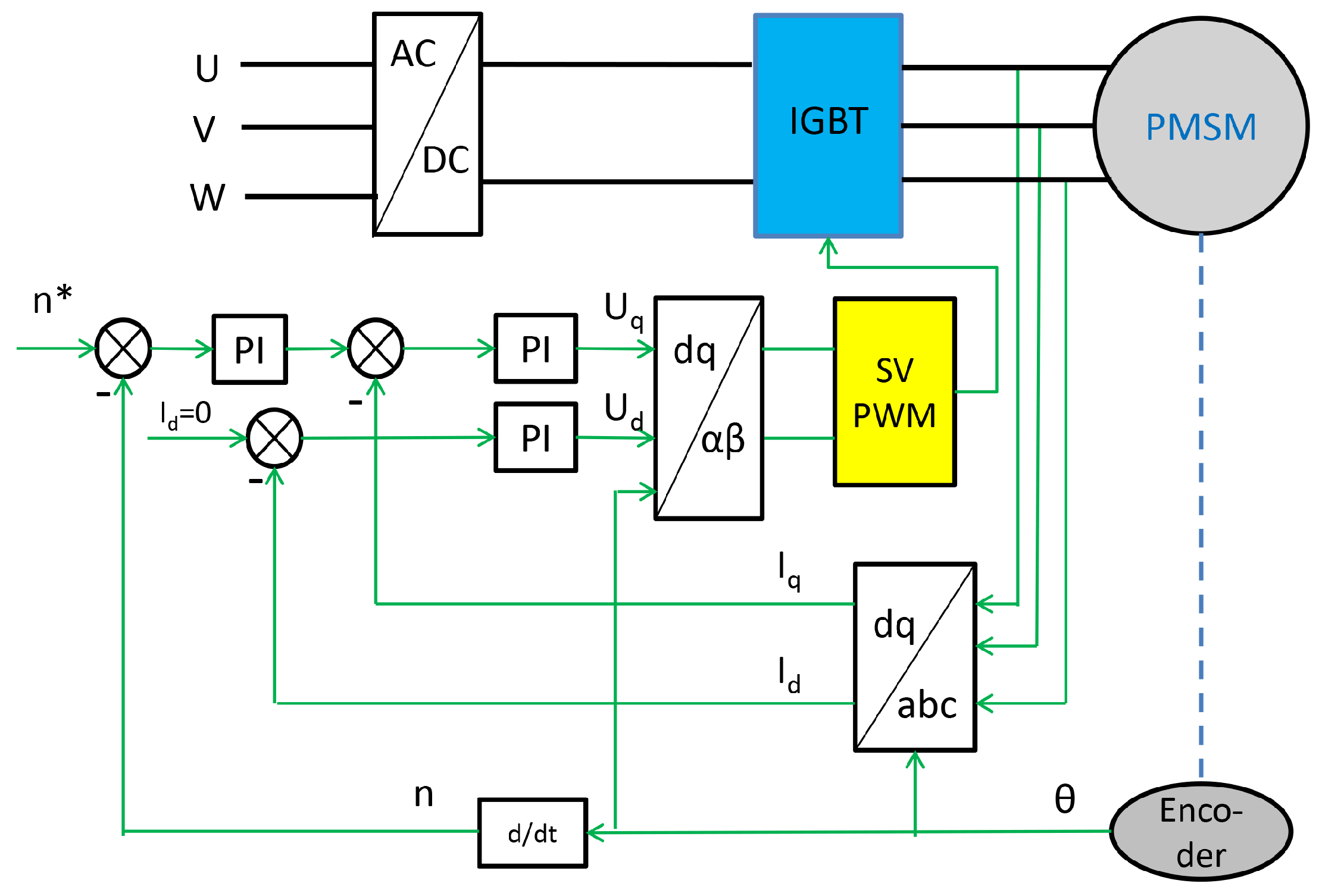
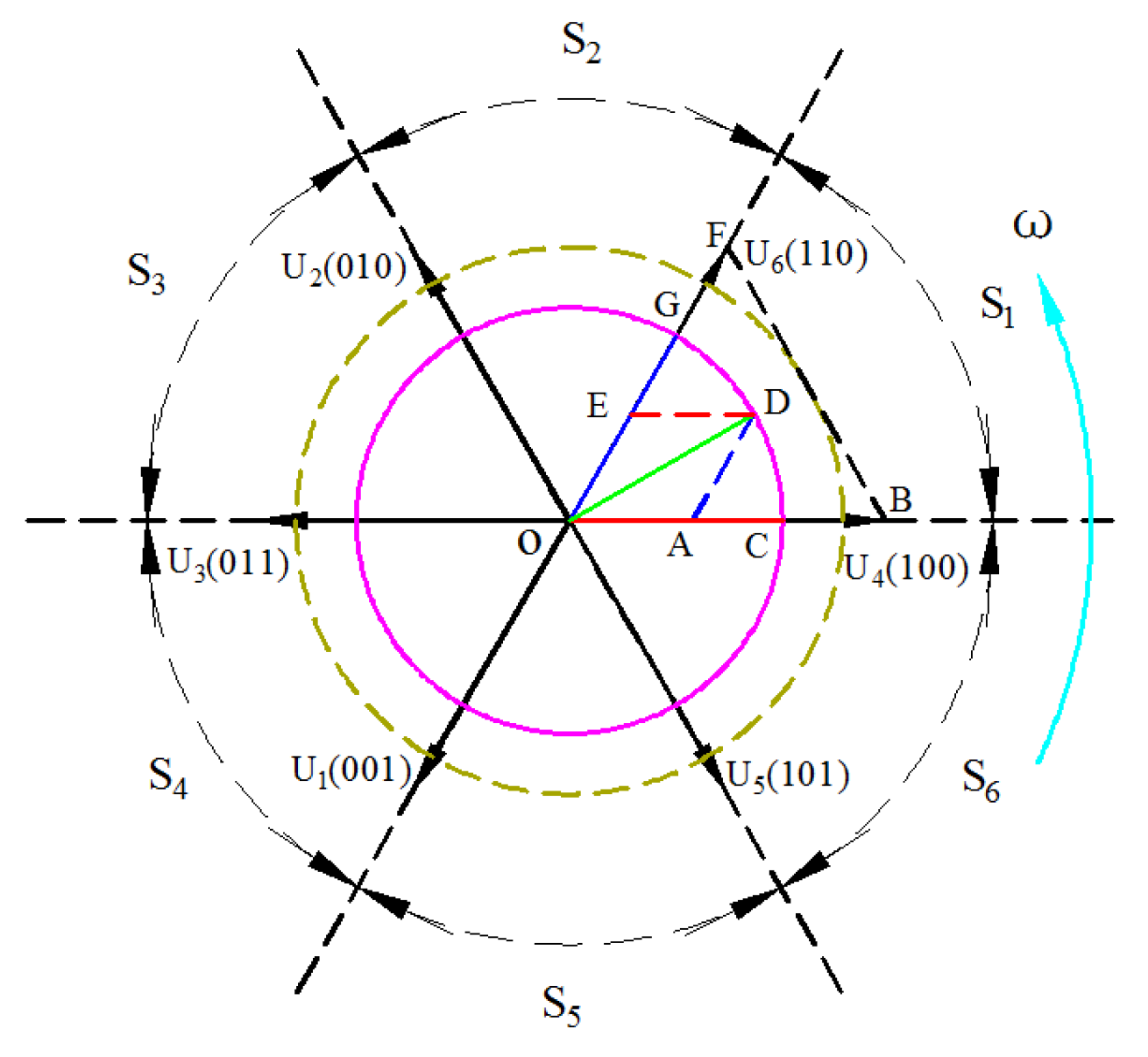
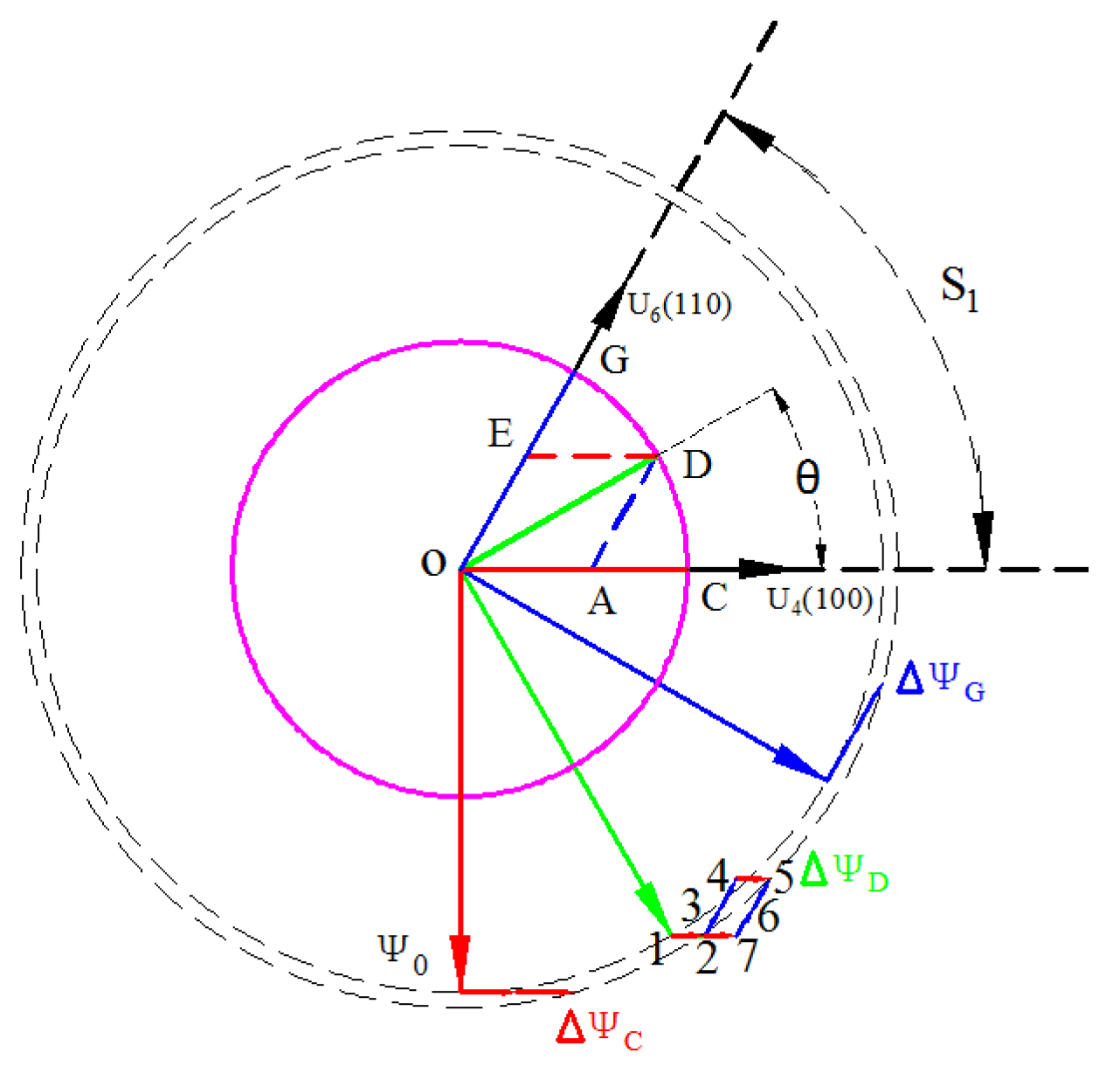
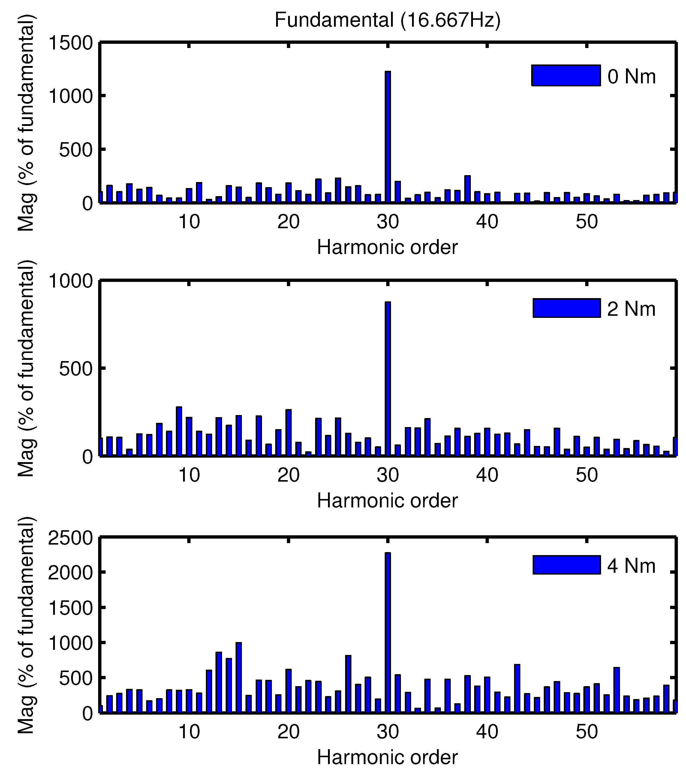
2. Torque Ripple Characteristics Caused by Conventional Space Vector Pulse Width Modulation Control

The conventional SVPWM control model of PMSM is shown in Figure 1.
During the SVPWM control process, a required voltage vector is synthesized by a mentioned manner in [20]. At steady state, three locations of C, D ( D O C = π / 6 ) and G in the first section S 1 are analyzed, where the amplitude of the synthesized voltage vector is equal to | O C | as shown in Figure 2. ω is the rotational direction of the voltage vector. The action time of U 4 and U 6 are given in Table 1, where T s is the modulation period of the SVPWM.
When the synthesized voltage vector was located at the first sector S 1 , the stator flux of the PMSM in one SVPWM modulation period can be expressed in the Equation (1):
ψ s = ψ 0 + Δ ψ = ψ 0 + U 4 t 4 + U 6 t 6 .
In the three locations of the synthesized voltage vector above, the 7-segment control strategy of the SVPWM should be used to ensure only one switch operation for each switch condition. At the positions of C, D and G, the switching state sequence is U 0 ( 000 ) - U 4 ( 100 ) - U 6 ( 110 ) - U 7 ( 111 ) - U 7 ( 111 ) - U 6 ( 110 ) - U 4 ( 100 ) - U 0 ( 000 ) at sector S 1 . The flux changes of the synthesized voltage vector in an SVPWM period at locations of C, D and G are shown in Equations (2)–(4), respectively. Neither of the zero-voltage vectors U 0 ( 000 ) and U 7 ( 111 ) in the process of action change the value of the flux. The loci of flux changes at locations C, D and G are shown in Figure 3.
When the synthesized voltage vector is located at C, the changes of flux within an SVPWM period can be expressed in Equation (2):
ψ C = u × t = O B × O C O B T s = O C × T s .
When the synthesized voltage vector is located at D ( D O C = π / 6 ), the changes of flux within a SVPWM period can be expressed in Equation (3):
ψ D = u × t = U 4 × t 4 + U 6 × t 6 e j π 3 = O B × O A O B × T s + O F × O E O F × T s e j π 3 = O A × T s + O E × T s e j π 3 .
When the synthesized voltage vector is located at G, the changes of flux within an SVPWM period can be expressed in Equation (4):
ψ G = u × t = O F × O G O F T s e j π 3 = O G × T s e j π 3 .
As shown in Figure 3, when the 7-segment switch control strategy was adopted, the loci of flux changes were 1-2-3-4-5. Correspondingly, when the 5-segment switch control strategy was adopted, the loci of flux changes were 1-2-7-6-5. In both the 7-segment and 5-segment switch control strategies, the largest flux changes occurred when the voltage vector was located at D.
The 7-segment control strategy is the one most widely used in the SVPWM control model. When 0 < D O C π / 3 , it means that the synthesized voltage vector is located at sector S 1 . After the action time of the voltage vector of U 4 reaches t 4 / 2 , the magnitude of the stator flux can be expressed as Equation (5):
ψ t 4 2 = ψ 0 ( θ π 2 ) + U 4 × t 4 2 ( 0 ) = ψ 0 ( θ π 2 ) + O B × ( cos θ sin θ tan π 3 ) × T s × O D O B 2 ( 0 ) = ψ 0 cos ( θ π 2 ) + O D T s ( cos θ sin θ 3 ) 2 + j ψ 0 sin ( θ π 2 ) = ψ 0 2 cos 2 ( θ π 2 ) + ψ 0 O D T s ( cos θ sin θ 3 ) cos ( θ π 2 ) + O D 2 T s 2 ( cos θ sin θ 3 ) 2 4 + ψ 0 2 si n 2 ( θ π 2 ) 1 2 = ψ 0 2 + 2 3 ψ 0 O D T s sin θ ( 3 2 cos θ 1 2 sin θ ) + O D 2 T s 2 [ 2 3 ( 3 2 cos θ 1 2 sin θ ) ] 2 4 1 2 = ψ 0 2 + 2 3 ψ 0 O D T s cos ( θ + π 6 ) sin θ + 1 3 O D 2 T s 2 cos 2 ( θ + π 6 ) 1 2 .
Ignoring the small amount of second-order, Equation (5) can be rewritten as Equation (6):
ψ t = t 4 2 = L 2 ,
where:
L 2 = ψ 0 2 + 2 3 ψ 0 O D T s cos θ + π 6 sin θ = ψ 0 2 + 1 3 ψ 0 O D T s sin 2 θ + π 6 sin π 6 .
To obtain the greatest value of L 2 , the following condition should be satisfied:
d L 2 d θ = 2 3 ψ 0 O D T s cos 2 θ + π 6 = 0 .
It is obvious that:
θ = π 6 .
It can be judged from the derivation results that when the θ = π / 6 , the maximum value of stator flux is obtained.
At the end of the action time of voltage vector U 6 , the magnitude of the flux can be expressed as Equation (10):
ψ t 6 = ψ 0 ( θ π 2 ) + U 4 t 4 2 0 + U 6 t 6 π 3 = ψ 0 ( θ π 2 ) + O B ( cos θ sin θ 3 ) T s O D O B 2 0 + O F sin θ sin π 3 T s O D O F π 3 = ψ 0 sin θ + O D T s ( cos θ sin θ 3 ) 2 + O D T s sin θ sin π 3 cos π 3 j ψ 0 cos θ + j O D T s sin θ sin π 3 sin π 3 = ψ 0 sin θ + O D T s ( cos θ + sin θ 3 ) 2 + j ( O D T s sin θ ψ 0 cos θ ) = ψ 0 2 sin 2 θ + ψ O D T s ( cos θ + sin θ 3 ) sin θ + O D 2 T s 2 ( cos θ + sin θ 3 ) 2 4 + O D 2 T s 2 sin 2 θ 2 ψ 0 O D T s sin θ cos θ + ψ 0 2 cos 2 θ 1 2 = ψ 0 2 + 2 3 ψ 0 O D T s cos ( θ π 6 ) sin θ + O D 2 T s 2 co s 2 ( θ π 6 ) 3 + O D 2 T s 2 sin 2 θ 2 ψ 0 O D T s sin θ cos θ 1 2 = ψ 0 2 + 1 3 ψ 0 O D T s [ sin ( 2 θ π 6 ) + sin π 6 ] ψ 0 O D T s sin 2 θ + O D 2 T s 2 co s 2 ( θ π 6 ) 3 + O D 2 T s 2 sin 2 θ 1 2 .
Ignoring the small amount of second-order, Equation (10) can be rewritten as Equation (11):
ψ t = t 6 = L 3 ,
where:
L 3 = ψ 0 2 + 1 3 ψ 0 O D T s [ sin ( 2 θ π 6 ) + sin π 6 ] ψ 0 O D T s sin 2 θ .
To obtain the greatest value of L 3 , the following condition should be satisfied:
d L 3 d θ = 2 3 cos ( 2 θ π 6 ) 2 cos 2 θ = 0 .
It is obvious that:
θ = π 6 .
It can be judged from the derivation results that θ = π / 6 , and the minimum value of stator flux is obtained.
From Equations (9) and (14), the greatest fluctuations of stator flux were present in the voltage vector located at the middle ( θ = ( 2 k 1 ) × π / 6 , k = 1 , 2 , 3 , 4 , 5 , 6 ) of the sector, and occur once in each sector.
In a PMSM, the electromagnetic torque can be expressed in Equation (15):
T e = 3 n p 2 L s ψ s ψ f sin δ ,
where T e is the electromagnetic torque of the motor, ψ f is the permanent-magnet flux, L s is the inductance of the motor, ψ s is the magnitude of flux generated by the stator current, and δ is the load angle of the motor.
While the motor operated in a stable state, the changes of load angle δ were very small and can be ignored. Equation (15) shows that changes of torque are related to flux amplitude. In the section S 1 , as shown in graphical and mathematical analyses, the position of maximum is θ = π / 6 . According to the same method, the largest flux fluctuation amplitude occured while the voltage vector was located at the middle ( θ = ( 2 k 1 ) × π / 6 , k = 1 , 2 , 3 , 4 , 5 , 6 ) of the sector of each discrete PWM control period.
It can be obtained that the maximum flux fluctuation amplitude occurs six times in an electrical cycle. When the motor rotated in one mechanical cycle, the maximum flux fluctuation amplitude occurred 6P times (P refers to the pole pairs of PMSM). Thus, the main harmonic frequency of torque ripple was 6P times the rotor mechanical frequency with the SVPWM control mode. The amplitude of torque ripple will increase as PWM period increases.

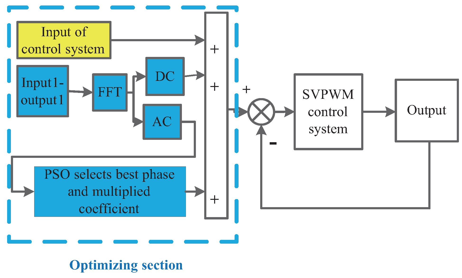
3. A Harmonic Superposed Model to Reduce Speed Ripple

The traditional simplified SVPWM control model of a PMSM is shown in Figure 4.
Inspired by the development of active noise reduction technology, a harmonic injecting method can improve motor performance [17,26]. Injecting superposed harmonics into the pole shape can reduce torque ripple of the motor during the design process [27]. The harmonic current injection method has been used to reduce motor torque ripple [28]. However, no literature has been found by the authors focusing on the reduction of torque ripple of a PMSM by changing the reference signals. This paper presents a new method to reduce speed ripple by injecting harmonics into the reference signal.
In a PMSM, the relation between torque and speed can be expressed in Equation (16):
J d ω d t = T e T L ,
where J is the moment of inertia, ω is the angular velocity, T e is the electromagnetic torque, and T L is the load torque.
The speed ripple of the motor comes from the pulsating torque. In this paper, the focus is on reducing the speed ripple in the SVPWM control system of a PMSM. The rotational speed of PMSM in a non-optimized system can be a Fourier decomposition. The expression of decomposed speed is shown in Equation (17):
n ( t ) = A 0 + N = 1 A N sin ( N ω t + θ N ) .
The difference between the results of a Fourier decomposition and the original reference signal can be obtained in a non-optimized system. The direct current (DC) component of the difference superposes reversely on the speed reference signal of the control system. Because delay is present in the control system, the main alternating current (AC) harmonic component of the difference needs the proper phase angle. To make sure that the speed output is as close as possible to a smooth straight line, a multiplier coefficient of the AC component should be selected properly as well. The optimized system model is shown in Figure 5.

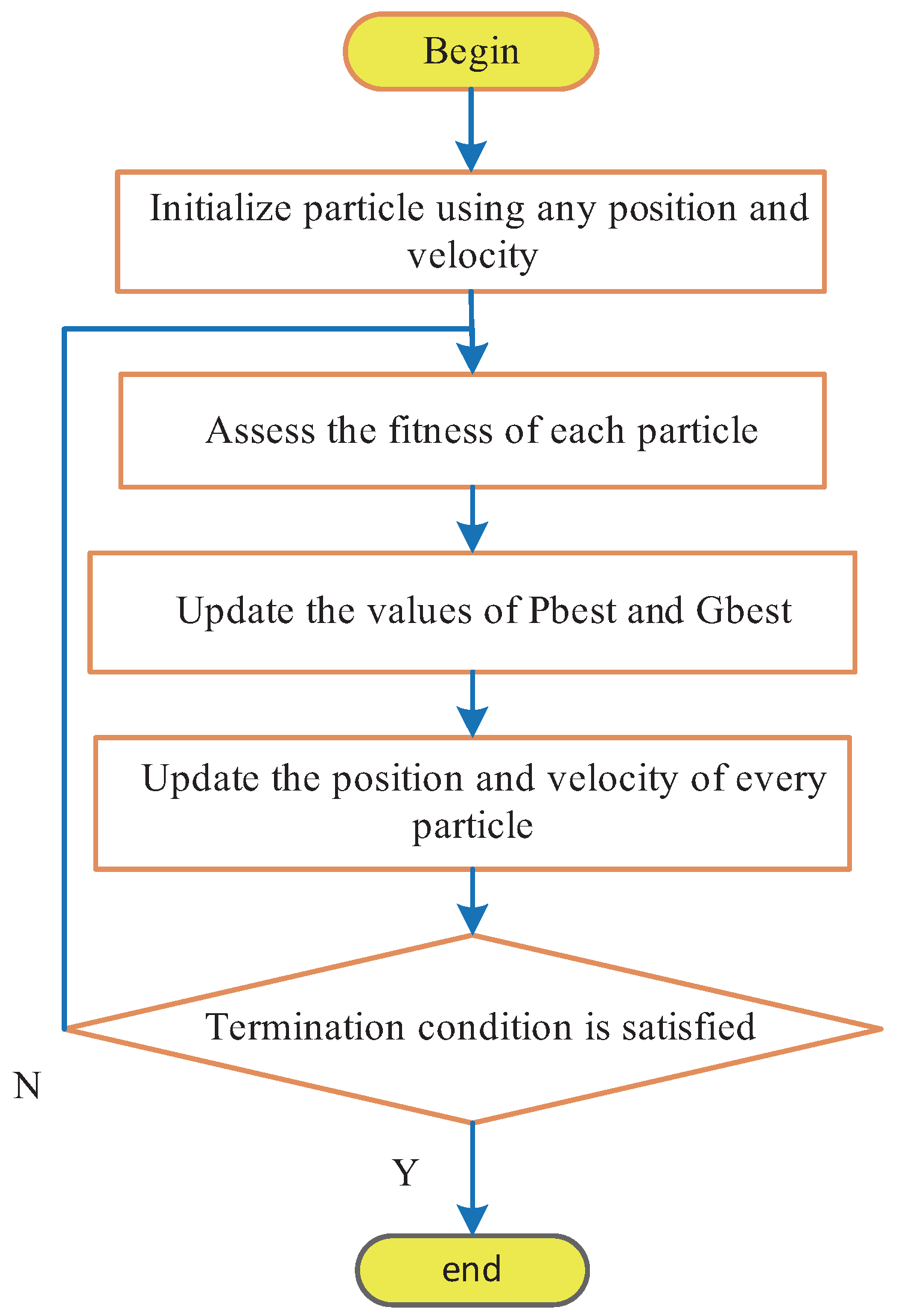
4. The Particle Swarm Optimization Algorithm and Its Application in Reducing the Speed Ripple Control Model of Superposed Harmonics

The PSO algorithm was derived from the process of a foraging flock of birds. The basic idea of the algorithm is to find the optimal solution through collaboration and information sharing among groups. It was first proposed by Eberhart and Kennedy in 1995 [29]. In recent years, because of its simplicity and effectiveness in solving the optimization problem, it has had a wide range of applications. The initialization system groups random “particles” by finding the optimal value iteratively. In each iteration process, every “particle” updates its position and velocity, which depend on the global and local optimum value of the particle. The PSO algorithm terminates when it reaches optimum conditions or arrives at the maximum number of iterations. The procedure of the PSO algorithm is given shown in Figure 6.
In each iteration process, the rule by which every particle updates position and velocity is given in Equation (18):
v ( i + 1 , : ) = ω × v ( i , : ) + c 1 × r a n d 1 × ( p i d x ( i , : ) ) + c 2 × r a n d 2 × ( p g d x ( i , : ) ) x ( i + 1 : ) = x ( i , : ) + v ( i + 1 , : ) ,
where v ( i + 1 , : ) and v ( i , : ) are the speed values of the particle velocity in the i + 1 and i steps, respectively, ω is inertia weight, c 1 and c 2 are the learning factors, x ( i + 1 , : ) and x ( i , : ) are the positions of the particle in the i + 1 and i steps, respectively, r a n d 1 and r a n d 2 are two random numbers in the range [0, 1], p i d is the best one of the solutions this particle has reached, and p g d is the best one of the solutions that all of the particles have reached.
In the proposed implementing process, speed ripple minimization is the final optimization goal. The optimized parameter is the phase angle and multiplier coefficient of the superposed harmonics in the reference signal. In the process, the variation range of the optimized phase angle is one period of the superposed harmonic. The initialization “particle” is a 10 × 2 random matrix; and multiplier coefficient and phase angle compose its first and second rows, respectively. The learning factors adopt empirical values as c 1 = c 2 = 2 originally.
In this paper, the main non-optimized harmonic component of the FFT result is taken as the superposed harmonic that is injected into the reference signal. Based on the analysis result in Section 2, the main harmonic component is the 6P harmonic of the mechanical speed. The expression of the superposed AC component is given as Equation (19):
n + r i p = k sin ( 6 P × 2 π n a v 60 × t + φ ) ,
where n a v is the average speed of the non-optimized control system, k is the multiplier coefficient of the superposed harmonics, and φ is the phase angle of the superposed harmonics.
The phase angle φ and the multiplier coefficient k of the superposed harmonics are the parameters to be optimized. The optimization goal is to minimize the square difference of speed. The optimized objective function is given as Equation (20):
i = 1 N ( n ( i ) n s e t ) 2 ,
where N is the sampling number, and n s e t is the reference speed.

5. Simulation Results

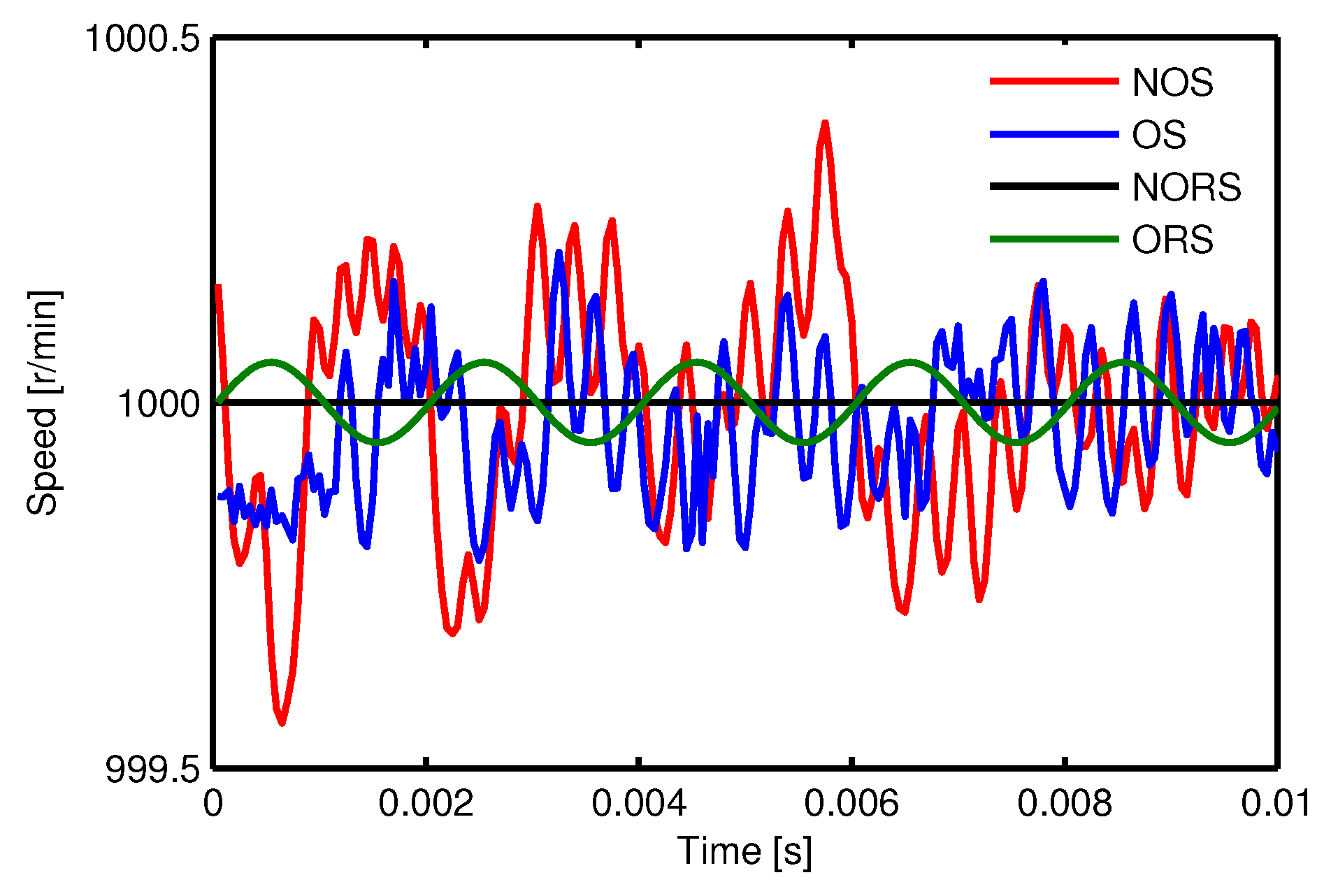
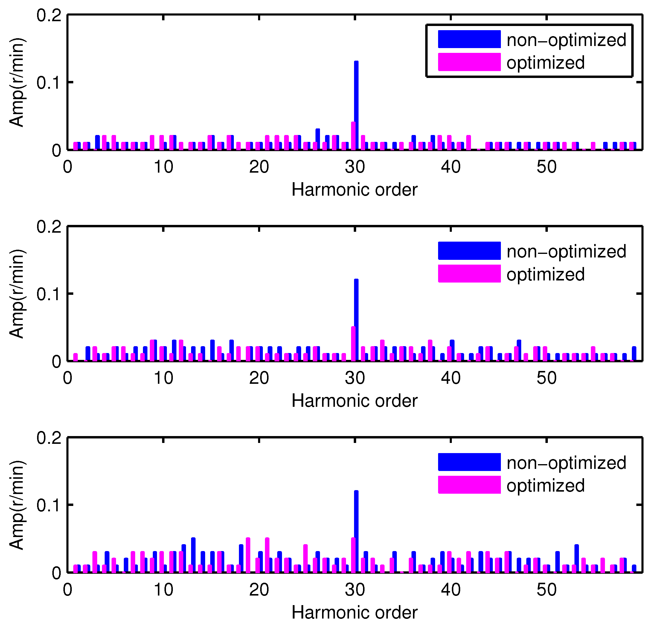
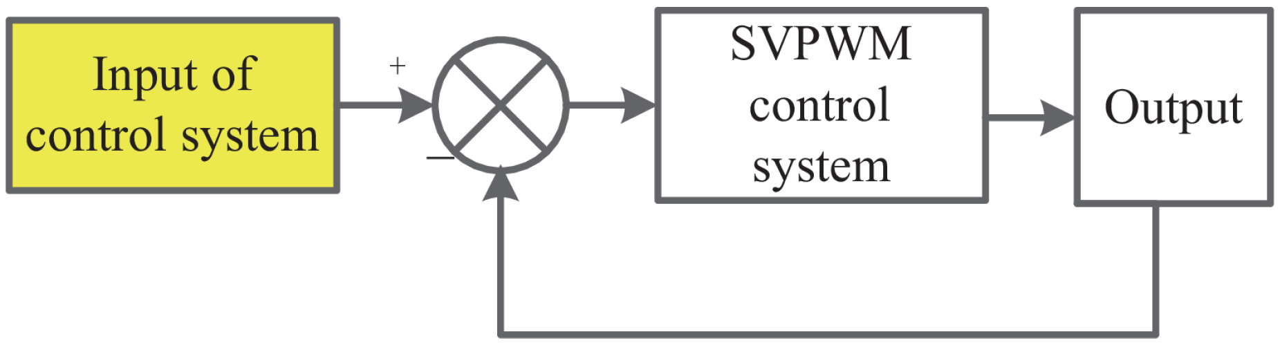
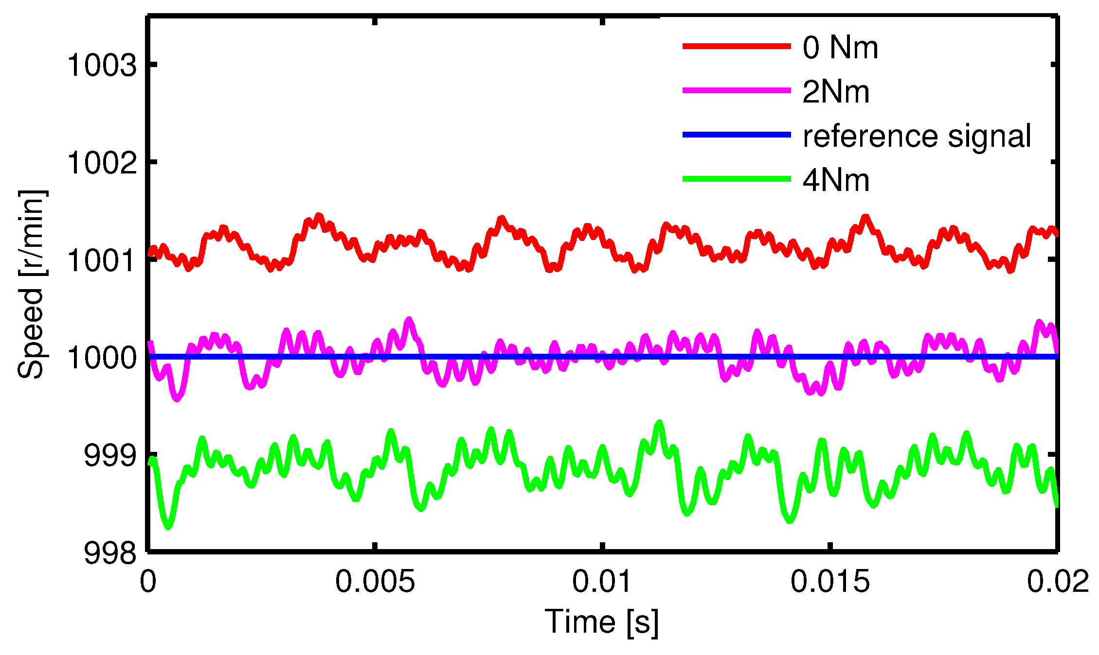
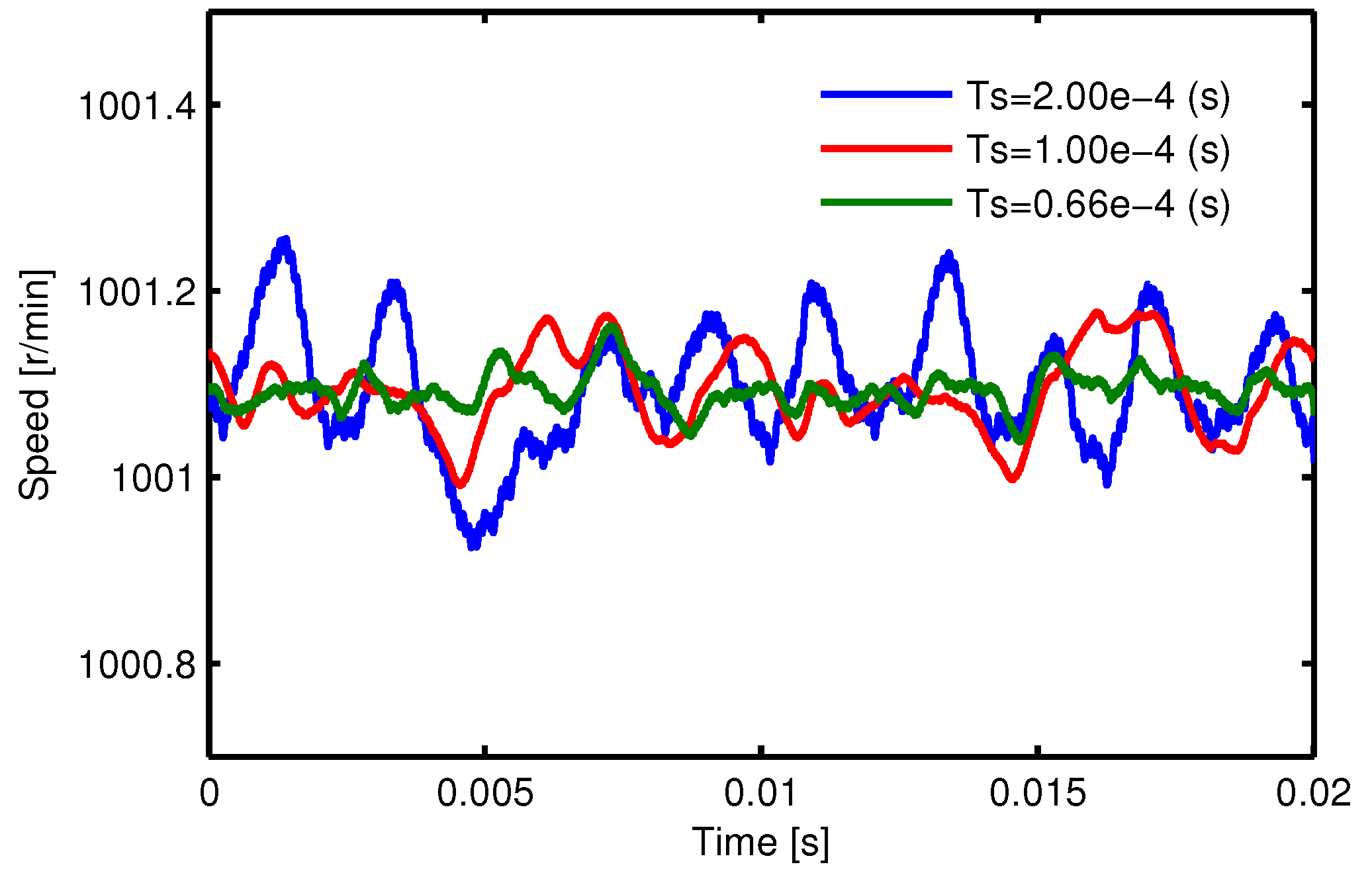
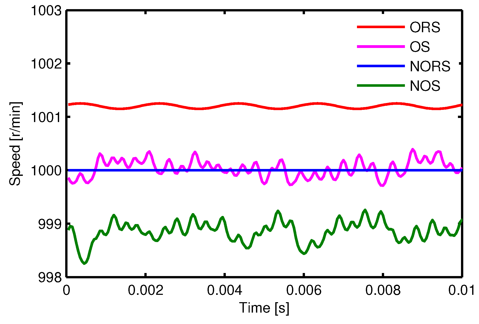
5.1. The Non-Optimized Results

The SVPWM control simulation model of the PMSM was established in MATLAB software (R2011a, MathWorks, Natick, MA, USA). The control block of the non-optimized simulation model adopted the structure of Figure 1. The parameters of the PMSM used in the simulation model are given in Table 2.
The reference speed of the simulation was 1000 r/min, and the load torques of the PMSM in the simulation model is 0 Nm, 2 Nm and 4 Nm. The simulation results show that when no harmonic was superposed on the reference signal to reduce the speed ripple, the actual speed of the PMSM and the FFT results of the actual speed were as shown in Figure 7 and Figure 8, respectively.
When the load torque of the PMSM was 0 Nm, the results of the PMSM speed with different periods of PWM were as shown in Figure 9.
As shown in Figure 7, there were fluctuations and static error in the speed of rotation at both the no-load and the load conditions. As shown in Figure 8, from the FFT results, the main harmonic component of the rotational speed ripple was 30 (6P = 30) times the harmonic. As shown in Figure 9, the speed fluctuations varied with the change of PWM period: the smaller the period of PWM, the smaller the speed fluctuations obtained.

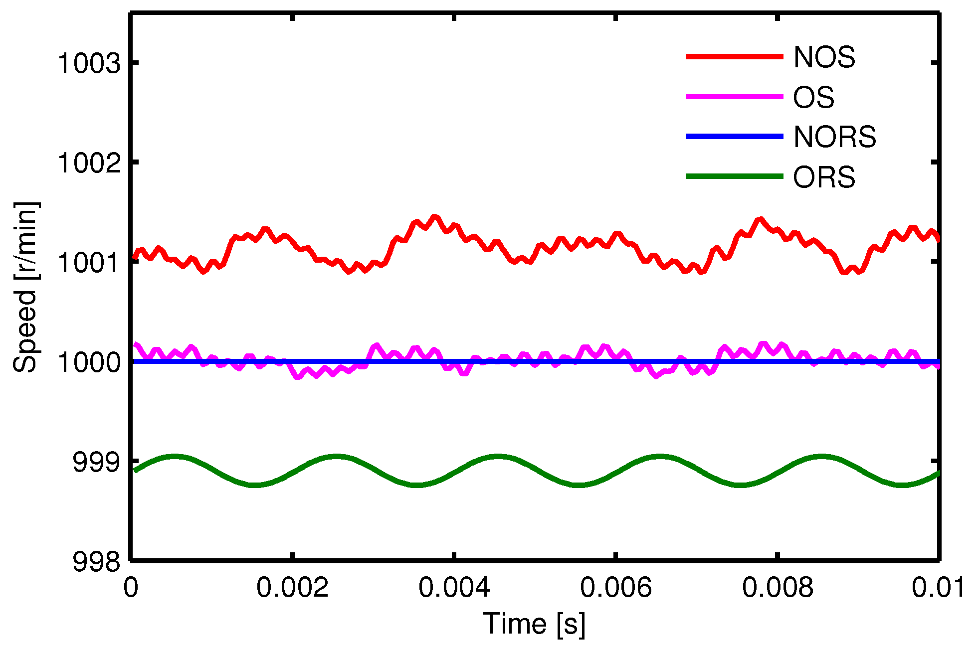
5.2. The Optimized Results

The PSO algorithm was used to determine the optimal phase angle and multiplier coefficient of the superposed harmonic to reduce speed ripple. The control block of the optimized simulation model adopted the structure shown in Figure 5. Based on the FFT result of the non-optimized model, the main harmonic component of the rotational speed ripple was 6P harmonic. For the optimized model in Figure 5, the components superposed to the reference signal include two parts of the DC section and the harmonic section. The value of the DC section is derived from the difference between the reference speed and the average value of measured speed. The function of the 6P harmonic is constructed in accordance with Equation (19). The phase angle φ and the multiplier coefficient k in Equation (19) are the parameters to be optimized. In the simulation, the ranges of k and φ are set as [ 0 , 10 ] and [ 0 , 2 π ] , separately. During the iterative process, the optimization program starts from the same rotor position after the motor reaching steady state. After the end of the PSO program, the minimum value of the Equation (20) is found. Thus, the optimized parameters of k and φ can be obtained.
The optimized result of the PMSM speed when the load torque was 0 Nm, 2 Nm and 4 Nm in Figure 10, Figure 11 and Figure 12, respectively. NOS, OS, NORS, and ORS represent non-optimized speed, optimized speed, non-optimized reference speed, and optimized reference speed, respectively.
The comparison of the FFT results between non-optimized and optimized models was given in Figure 13. These results were shown as the amplitudes of the harmonics.
It can be seen from the optimized simulation results that the harmonic signal superposed on the speed reference signal significantly reduced the speed ripple and almost completely eliminated the static error. The amplitudes of the harmonics have a significant decrease.
The speed ripples were calculated using the following Equation (21):
n r i p = 1 N n i = 1 N n ( n ( i ) n a v ) 2 ,
where N n is the sampling number, and n a v is the average value of the speed.
A comparison of results between non-optimized and optimized models is shown in Table 3.
It can be observed from Table 3 that the differences between the optimized average speed and the reference value were all less than 0.05 r/min, whereas the load torques were 0 Nm, 2 Nm, and 4 Nm, and the value of speed ripples was reduced by 46%, 35%, and 23%, respectively.

6. Conclusions

A voltage source inverter is commonly adopted in the SVPWM control of a PMSM in a real control system. The SVPWM modulation scheme of the voltage vector will result in a speed ripple because of the discreteness of control. The proposed graphic and mathematical analysis method deduced the relationship between the frequency of speed ripple and the frequency of rotor mechanical speed. Analysis indicated that 6P times harmonics of the rotor mechanical speed is the main harmonic component in the SVPWM control system. A Fourier decomposition of speed was done in a simulation. The result verified the correctness of the analytical method. In this study, a harmonic superposed on the reference signal to reduce the speed ripple. Furthermore, the PSO algorithm is proposed to determine the optimal phase angle and multiplier coefficient. The optimized simulation model demonstrated the effectiveness of the proposed method. Speed ripple was decreased significantly.

Acknowledgments

This work was supported by the National Natural Science Foundation of China (51177125).

Author Contributions

Xing Liu and Deliang Liang conceived and designed this study. Xing Liu wrote this manuscript. Jinhua Du reviewed and edited this paper. All authors read and approved this paper.

Conflicts of Interest

The authors declare no conflict of interest.

References

  1. Zhao, J.; Li, B.; Gu, Z.X. Research on an axial flux PMSM with radially sliding permanent magnets. Energies 2015, 8, 1663–1684. [Google Scholar] [CrossRef]
  2. Li, Y.M.; Zhao, J.; Chen, Z.; Liu, X.D. Investigation of a five-phase dual-rotor permanent magnet synchronous motor used for electric vehicles. Energies 2014, 7, 3955–3984. [Google Scholar] [CrossRef]
  3. Xia, C.; Zhao, J.; Yan, Y.; Shi, J. A novel direct torque control of matrix converter-fed PMSM drives using duty cycle control for torque ripple reduction. IEEE Trans. Ind. Electron. 2014, 61, 2700–2713. [Google Scholar] [CrossRef]
  4. Ortega, C.; Arias, A.; Caruana, C.; Balcells, J.; Asher, G.M. Improved waveform quality in the direct torque control of matrix-converter-fed PMSM drives. IEEE Trans. Ind. Electron. 2010, 57, 2101–2110. [Google Scholar] [CrossRef]
  5. Zhang, Y.; Zhu, J. Direct torque control of permanent magnet synchronous motor with reduced torque ripple and commutation frequency. IEEE Trans. Power Electron. 2011, 26, 235–248. [Google Scholar] [CrossRef]
  6. Lee, S.; Kim, Y.-J.; Jung, S.-Y. Numerical investigation on torque harmonics reduction of interior PM synchronous motor with concentrated winding. IEEE Trans. Magn. 2012, 48, 927–930. [Google Scholar] [CrossRef]
  7. Jabbour, Z.; Riwan, A.; Moreau, S.; Van Rhijn, J.; Champenois, G. Identification and compensation of torque ripples of a PMSM in a haptic context. In Proceedings of the IECON 2010 36th Annual Conference on IEEE Industrial Electronics Society, Glendale, AZ, USA, 7–10 November 2010; pp. 1665–1670.
  8. Tripathi, A.; Khambadkone, A.M.; Panda, S.K. Torque ripple analysis and dynamic performance of a space vector modulation based control method for AC-drives. IEEE Trans. Power Electron. 2005, 20, 485–492. [Google Scholar] [CrossRef]
  9. Hsiao, C.Y.; Yeh, S.N.; Hwang, J.C. A novel cogging torque simulation method for permanent-magnet synchronous machines. Energies 2011, 4, 2166–2179. [Google Scholar] [CrossRef]
  10. Dorrell, D.G.; Popescu, M. Odd stator slot numbers in brushless DC machines—An aid to cogging torque reduction. IEEE Trans. Magn. 2011, 47, 3012–3015. [Google Scholar] [CrossRef]
  11. Jang, S.-M.; Park, H.-I.; Choi, J.-Y.; Ko, K.-J.; Lee, S.-H. Magnet pole shape design of permanent magnet machine for minimization of torque ripple based on electromagnetic field theory. IEEE Trans. Magn. 2011, 47, 3586–3589. [Google Scholar] [CrossRef]
  12. Liu, X.; Gu, Z.; Zhao, J. Torque ripple reduction of a novel modular arc-linear flux-switching permanent-magnet motor with rotor step skewing. Energies 2016, 9. [Google Scholar] [CrossRef]
  13. Pinky, K.; Reeba, S.V. Torque improvement in IPMSM for electric vehicle application. In Proceedings of the 2015 International Conference on Control Communication & Computing India (ICCC), Thiruvananthapuram, India, 19–21 November 2015; pp. 224–229.
  14. Jezernik, K.; Horvat, R.; Curkovic, M. A switching control strategy for the reduction of torque ripple for PMSM. IEEE Trans. Ind. Inf. 2013, 9, 1272–1279. [Google Scholar] [CrossRef]
  15. Flieller, D.; Ngac Ky, N.; Wira, P.; Sturtzer, G.; Abdeslam, D.O.; Merckle, J. A self-learning solution for torque Rripple reduction for nonsinusoidal permanent-magnet motor drives based on artificial neural networks. IEEE Trans. Ind. Electron. 2014, 61, 655–666. [Google Scholar] [CrossRef]
  16. Xiao, X.; Chen, C. Reduction of torque ripple due to demagnetization in PMSM using current compensation. IEEE Trans. Appl. Supercond. 2010, 20, 1068–1071. [Google Scholar] [CrossRef]
  17. Fei, M.; Zanasi, R. Control of a five-phase synchronous motors with third harmonic constrained injection. In Proceedings of the 2011 9th IEEE International Conference on Control and Automation (ICCA), Santiago, Chile, 19–21 December 2011; pp. 957–962.
  18. Lu, J.; Yang, J.; Ma, Y.; Ren, R. Compensation for harmonic flux and current of permanent magnet synchronous motor by harmonic voltage. In Proceedings of the 2015 International Conference on Informatics, Electronics & Vision (ICIEV), Fukuoka, Japan, 15–18 June 2015; pp. 1–5.
  19. Lee, G.H.; Kim, S.I.; Hong, J.P.; Bahn, J.H. Torque ripple reduction of interior permanent magnet synchronous motor using harmonic injected current. IEEE Trans. Magn. 2008, 44, 1582–1585. [Google Scholar]
  20. Wang, M.; Yang, J.; Zhu, C. Hybrid SVPWM technique for reduced torque ripple in permanent magnet synchronous motor. In Proceedings of the 2014 International Electronics and Application Conference and Exposition (PEAC), Shanghai, China, 5–8 November 2014; pp. 1297–1302.
  21. Huang, M.L. Hybridization of chaotic quantum particle swarm optimization with SVR in electric demand forecasting. Energies 2016, 9. [Google Scholar] [CrossRef]
  22. Peng, L.L.; Fan, G.F.; Huang, M.L.; Hong, W.C. Hybridizing DEMD and quantum PSO with SVR in electric load forecasting. Energies 2016, 9. [Google Scholar] [CrossRef]
  23. Xiao, Y.; Zhang, T.; Ding, Z.; Li, C. The study of fuzzy proportional integral controllers based on improved particle swarm optimization for permanent magnet direct drive wind turbine converters. Energies 2016, 9. [Google Scholar] [CrossRef]
  24. Calvini, M.; Carpita, M.; Formentini, A.; Marchesoni, M. PSO-based self-commissioning of electrical motor drives. IEEE Trans. Ind. Electron. 2015, 62, 768–776. [Google Scholar] [CrossRef]
  25. Ma, C.; Qu, L. Multiobjective optimization of switched reluctance motors based on design of experiments and particle swarm optimization. IEEE Trans. Energy Convers. 2015, 30, 1144–1153. [Google Scholar] [CrossRef]
  26. Wang, J.; Qu, R.; Zhou, L. Dual-rotor multiphase permanent magnet machine with harmonic injection to enhance torque density. IEEE Trans. Appl. Supercond. 2012, 22, 5202204. [Google Scholar] [CrossRef]
  27. Wang, K.; Zhu, Z.Q.; Ombach, G. Torque improvement of five-phase surface-mounted permanent magnet machine using third-order harmonic. IEEE Trans. Energy Convers. 2014, 29, 735–747. [Google Scholar] [CrossRef]
  28. Yong, L.; Shuai, Z.; Ren, L.; Jun, Y. Torque ripple suppression of permanent magnet synchronous motor by the harmonic injection. Proc. CSEE 2011, 31, 119–127. [Google Scholar]
  29. Eberhart, R.; Kennedy, J. A new optimizer using particle swarm theory. In Proceedings of the Sixth International Symposium on Micro Machine and Human Science (MHS ’95), Nagoya, Japan, 4–6 October 1995; pp. 39–43.
Figure 1. The conventional space vector pulse width modulation (SVPWM) control blocks of permanent magnet synchronous motors (PMSM). AC: alternating current; DC: direct current; and IGBT: insulated-gate bipolar transistor.
Energies 09 00923 g001
Figure 2. Synthesis schemes of the space voltage vector.
Energies 09 00923 g002
Figure 3. Flux changes the schematic diagram of locations C, D and G.
Energies 09 00923 g003
Figure 4. Simplified SVPWM control model.
Energies 09 00923 g004
Figure 5. Optimized system model. FFT: Fourier fast transform.
Energies 09 00923 g005
Figure 6. Procedure algorithm of particle swarm 0ptimization (PSO).
Energies 09 00923 g006
Figure 7. Actual speed of the PMSM.
Energies 09 00923 g007
Figure 8. FFT results of the actual speed.
Energies 09 00923 g008
Figure 9. PMSM speed with different periods of PWM.
Energies 09 00923 g009
Figure 10. Optimized results of the speed with a 0 Nm load.
Energies 09 00923 g010
Figure 11. Optimized results of the speed with a 2 Nm load.
Energies 09 00923 g011
Figure 12. Optimized results of the speed with a 4 Nm load.
Energies 09 00923 g012
Figure 13. Comparison of FFT results between non-optimized and optimized.
Energies 09 00923 g013
Table 1. Action times of U 4 and U 6 at the locations of space vectors is C, D and G.
The Location of Synthesized Voltage Vectort4 Refers to the Action Time of U4t6 Refers to the Action Time of U6
C t 4 = | O C | / | O B | × T s t 6 = 0
D t 4 = | O A | / | O B | × T s t 6 = | O E | / | O F | × T s
G t 4 = 0 t 6 = | O G | / | O F | × T s
Table 2. The parameters of permanent magnet synchronous motor (PMSM) used in the simulation model.
ParameterValue
Pole pairs5
D-axis inductance0.827 mH
Phase resistance0.258 Ω
Moment of inertia0.0065 kg.m2
Q-axis inductance0.827 mH
Flux permanent magnet0.057 V.s
Table 3. Comparison between non-optimized and optimized models.
ParameterLoad Torque (Nm)Non-Optimized Speed (r/min)Optimized Speed (r/min)
n a v 01001.13111000.0204
2999.9973999.9826
4998.83871000.0494
n r i p 00.13310.0709
20.15720.0997
40.20230.1557

