Article

Effects of Scavenging System Configuration on In-Cylinder Air Flow Organization of an Opposed-Piston Two-Stroke Engine

1
School of Mechanical and Vehicle Engineering, Beijing Institute of Technology, Zhongguancun South Street No.5, Beijing 100081, China
2
School of Mechanical and Power Engineering, North University of China, University Road No.3, Taiyuan 030051, China
*
Author to whom correspondence should be addressed.
Energies 2015, 8(6), 5866-5884; https://doi.org/10.3390/en8065866
Submission received: 17 March 2015 / Revised: 12 May 2015 / Accepted: 9 June 2015 / Published: 17 June 2015
(This article belongs to the Special Issue Electrical Power and Energy Systems for Transportation Applications)

Abstract

:
In-cylinder air flow is very important from the point of view of mixture formation and combustion. In this direction, intake chamber structure and piston crown shape play a very crucial role for in-cylinder air pattern of opposed-piston two-stroke (OP2S) engines. This study is concerned with the three-dimensional (3D) computational fluid dynamics (CFD) analysis of in-cylinder air motion coupled with the comparison of predicted results with the zero-dimensional (0D) parametric model. Three configurations viz., a flat piston uniform scavenging chamber, a flat piston non-uniform scavenging chamber and a pit piston non-uniform scavenging chamber have been studied. 0D model analysis of in-cylinder air flow is consistent with 3D CFD simulation. It is concluded that a pit piston non-uniform scavenging chamber is the best design from the point of view of tumble ratio, turbulent kinetic energy and turbulent intensity, which play very important roles in imparting proper air motion. Meanwhile a flat piston uniform scavenging chamber can organize a higher swirl ratio and lower tumble ratio which is important to improve the scavenging process.

Graphical Abstract

1. Introduction

The OP2S engine concept can be traced back to the late 1800s. Since then, many novel applications have been used in aircraft, ships and vehicles. In the first half of the 20th century, OP2S engines were developed in multiple countries for a wide variety of applications. However, modern emission regulations stopped widespread development of most two-stroke engines in the latter half of the 20th century [1]. In recent years, with the application of advanced design technology, modern analytical tools, materials and engineering methods, the emission problems no longer limit the successful design of a clean and efficient OP2S [2], so OP2S engines are once again attracting intensive attention to improve engine efficiency and emission performance [3,4,5,6,7]. Compared with conventional engines, OP2S engines have many fundamental advantages [8]. The opposed-piston structure characterized by two pistons reciprocating opposite to each other in a common cylinder, cancels the need for the cylinder head and valve mechanism, which leads to lower heat loss for a higher wall temperature with two piston crowns compared to a cylinder head, while the nearly symmetrical movement of opposed pistons leads to excellent engine balance, even for single cylinder configurations.
For conventional two-stroke gasoline engines, the serious fuel short circuit loss during the scavenging process results in poor fuel economy and high emission levels. OP2S gasoline direct injection (GDI) engines use uniflow scavenging and GDI technology to separate the injection and scavenging processes. For GDI engines, the air-fuel mixture is formed in the cylinder, so in-cylinder fluid dynamics play a crucial role in the mixture formation and combustion process. On one hand, in order to accelerate air-fuel mixing, high intensity turbulence is required from a micro perspective. On the other hand, in-cylinder air motion velocity is needed for forming a homogenous mixture from a macro perspective [9]. Swirl, tumble and squish are used to form the air-fuel mixture. For conventional four-stroke GDI engines, in-cylinder flow organization depends on intake duct structure, inlet valve shape, bore-stroke ratio and combustion-chamber shape [10,11]. The injector is installed on the cylinder head. Because injection happens in the intake process, mixing time is more than sufficient. For OPTS-GDI engines, mixture formation time is short since the fuel injection process mainly occurs during the compression process. Fluid motion inside the cylinder is inherently unsteady, turbulent and three dimensional. Gas motion is unstable during the scavenging and compression processes and breaks down into three dimensional turbulent motions. Therefore, a proper understanding of in-cylinder air motion organization and also the effect of intake chamber structure and piston configuration are required to improve mixture formation.
Nowadays, a number of cold and hot flow CFD simulation studies have been carried out to understand in-cylinder flow field, combustion and emission processes in IC engines [12,13,14,15]. These investigations have shown that complex flow structures like swirl, tumble and turbulence exist inside the engine cylinder, even after the closure of the intake valve [16]. Nordgren et al. [17] studied the in-cylinder air motion through experimental and theoretical methods viz., PIV and CFD. Sweetland and Reitz [18] used the KIVA code to study the in-cylinder flow field during the intake and compression strokes using real intake port geometry and moving intake valves. They reported that turbulent kinetic energy estimated from the PIV photographs agreed well with the KIVA code. Gunasekaran and Ganesan [19] simulated the fuel-air interaction in a four stroke four valve direct injected spark ignition engine and reported that in order to achieve a combustible fuel-air mixture near the spark plug, proper air motion during induction and compression process is necessary. Rakapoulos et al. [20] investigated the three piston bowl geometries in diesel engines through CFD against a quasi-dimensional model by changing the ratio of piston bowl diameter to cylinder diameter. They concluded that both the models predicted similar cylinder pressure and temperature as well as axial and radial velocities. Lin et al. [21], Shimoda et al. [22] and Dolak et al. [23] reported that even though the shape and design of the intake port play a predominant role in generating tumble, the combustion chamber geometry also plays a part in vortex formation, turbulence generation, combustion and emission processes in an internal combustion engine. In [24] the authors used numerical simulation to assess the influence of some intake duct geometrical parameters on the tumble motion generation during both the intake and the compression strokes to highlight the turbulence production process. In [25] the authors presented a theoretical model capable of describing the interaction between the squish velocity and the tumble velocity depending on the engine class. Ramajo et al. [26] reported results obtained running a mono-dimensional (1D) model developed for predicting in-cylinder tumble motion formation and breakdown till the appearance of high turbulence level close to TDC.
From the literature survey, it is clear that for conventional two-stroke gasoline engines the in-cylinder fluid flow is heavily dependent on the intake duct structure, inlet valve shape, bore-stroke ratio and combustion-chamber shape. However, limited research exists about the effect of intake chamber structure and piston bowl configuration on the in-cylinder flow characteristics. The aim of the paper is to introduce a new analysis approach to provide deep insight into the 0D parametric model development and 3D-CFD results performed to assess the intake chamber structure influence on the optimization of the in-cylinder flow organization during both the scavenging and compression processes. All the CFD simulations presented in the paper were performed by the AVL-Fire CFD code on an OPTS-GDI engine characterized by a unit displacement of 250 cm3. The scavenging flow was changed during the analysis by changing the scavenging system configuration. The effects of in-cylinder air motion variations were evaluated in terms of the tumble ratio, swirl ratio, the turbulent kinetic energy and the squish characterization before inner dead center (IDC).

2. OP2S Engine Scavenging System

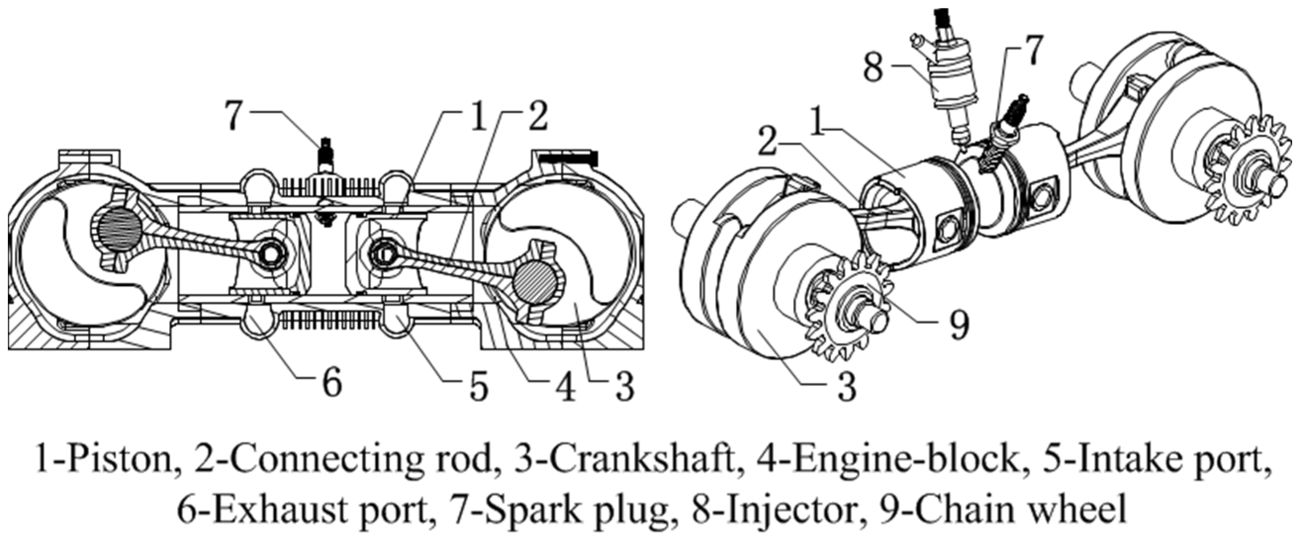
2.1. Engine Configuration

As shown in Figure 1, the OPTS-GDI engine is equipped with a GDI system and a “port-to-port” uniflow scavenging system, and its injector and spark plug are placed on the cylinder liner. The opposed crank-connecting rod mechanism is placed on both sides of cylinder body and a chain transmission mechanism is designed to realize the synchronized working of opposed pistons. On both sides of the cylinder liner there are gas ports, an intake ports on one side and an exhaust port on the other side. Intake ports are used to deliver fresh air into the cylinder, and exhaust port are used to remove exhaust gas from the cylinder. In the working process, the piston motion controls the opening and closing of ports. There are two pistons placed in the cylinder liner, and the combustion chamber is formed when the two pistons move to the closest position. The reciprocating movements of pistons are driven by the opposed crank-connecting rod mechanism, and the synchronous movements of opposed pistons are ensured by the synchronous chain. With the exception of accomplishing energy conversion, the reciprocating movement can accomplish air-exchange by combining the position with the air ports. The piston which controls the opening and closing of intake air ports is defined as the intake piston and the piston which controls the opening and closing of the exhaust air ports is defined as the exhaust piston. When the distance between two pistons is minimized, it is defined as the inner dead center (IDC); when the distance between two pistons is maximized, it is defined as the outer dead center (ODC). The structure parameters are shown in Table 1.
Figure 1. OP2S-GDI engine.
Energies 08 05866 g001
Table 1. Engine specifications.
ParametersUnitValue
Boremm56
Strokemm49.5 (×2)
Connecting rodmm82.5
Effective compression Ratio10.5
Engine speedrpm6000
Number of intake ports10
Number of exhaust ports10
Intake port heightmm12
Exhaust port heightmm14
Intake port circumference ratio0.75
Exhaust port circumference ratio0.6
Intake port radial angle°15
Exhaust port radial angle°0
PowerkW15
Fuel consumption rateg/kW·h276
The exhaust port opens first before ODC and a blow down discharge process commences. The discharge period up to the time of the scavenging port opening is called the free exhaust period. The intake port opens also before ODC when the cylinder pressure slightly exceeds the scavenging pressure. When the cylinder pressure is less than the scavenging pressure fresh air enters the cylinder and the scavenging process starts. The intake port closes after the exhaust port closes, since the flow towards the intake port occurs continuously, and additional fresh air is obtained. The fuel injection starts after the exhaust port closes, which can avoid fuel short circuits. The spark plug fires before IDC, igniting the compressed air-fuel mixture which produces a powerful expansion of the vapor. On the expansion stoke, the opposed piston moves to ODC and the exhaust port is opened first.

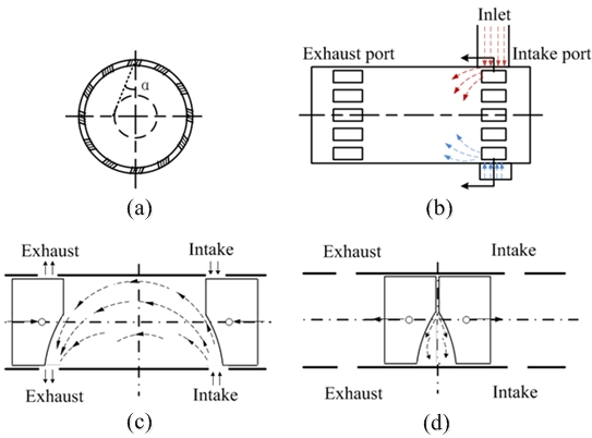
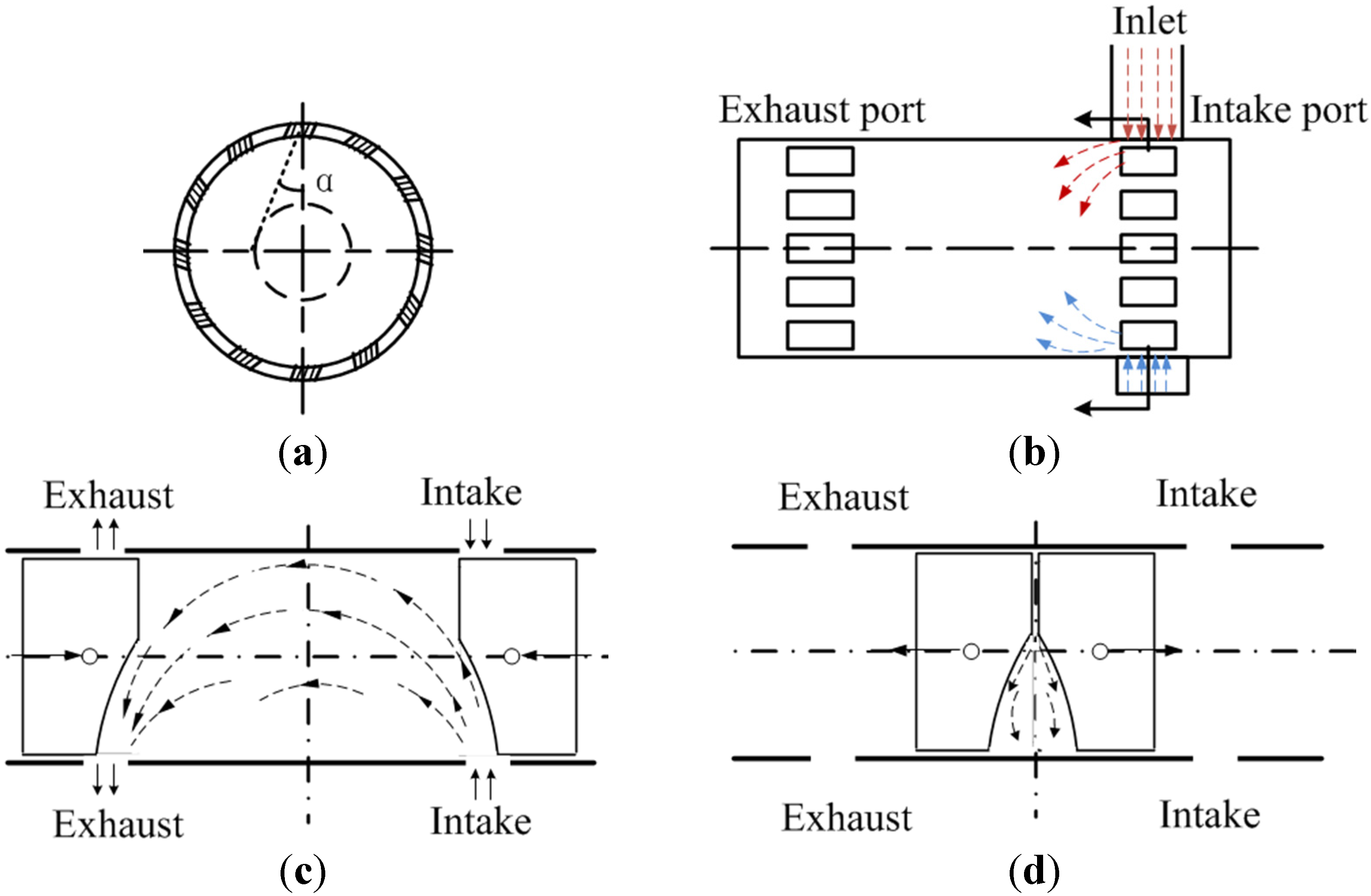
2.2. In-Cylinder Air flow Organization

The intake chamber structure affects scavenging flow resistance, initial swirl, tumble level and air motion velocity. By the design of a non-uniform intake chamber structure, the velocity and flow rate of intake ports away from the inlet are decreased because of wall friction and structural mutation. With respect to intake ports close to the inlet, as flow momentum is small, the velocity and mass flow are bigger. On these ground, the simulation studied uniform and non-uniform inlets, respectively, with the same radial angle of 15° and flat pistons and pit pistons with the same compression ratio, as shown in Figure 2.
Figure 2. Intake chamber schemes and piston crown. (a) Uniform; (b) non-uniform; (c) pit piston.
Energies 08 05866 g002
As shown in Figure 3, for the uniflow scavenging system OP2S engine, in-cylinder swirl is formed by intake port radial angle and tumble is formed by the non-uniform intake chamber and pit piston. In addition, the pit piston scheme is used to produce squish around IDC.
Figure 3. In-cylinder air flow organization. (a) Swirl organization by intake port radial angle; (b) tumble organization by non-uniform intake; (c) tumble organization by pit piston; (d) squish organization by pit piston.
Energies 08 05866 g003

3. Theoretic-Interpretative 0D Model

The current paper deals with the development of the 0D parametric model for qualitatively predicting how intake chamber schemes and piston crown affect the tumble, swirl and squish velocity value in the scavenging process and compression strokes, as shown in Figure 4.
Figure 4. Sketch of in-cylinder air flow. (a) Intake chamber and intake velocity vector; (b) tumble velocity vector distribution in scavenging process; (c) tumble velocity vector distribute in compression process; (d) sketch of the squish motion.
Energies 08 05866 g004

3.1. Tumble Velocity of Non-Uniform Scavenging Process

Under the hypothesis of steady flow conditions through the intake ports in the scavenging process, the expression for air mass flow can be written as the following form:
d m s d ϕ = μ s F s 6 n 2 g k k 1 p s R T ( p z p s ) 2 k ( p z p s ) k + 1 k
If the instantaneous flow velocity through the intake ports is v in in the scavenging process, the expression volume mass flow can be written as the following form:
d V s d ϕ = v in F s
By Equation (2), Equation (1) can be written as the following form:
v in = μ s 6 n ρ 2 g k k 1 p s R T ( p z p s ) 2 k ( p z p s ) k + 1 k
Because of the non-uniform scavenging process, every intake port has a different instantaneous flow velocity vin_i, as shown in Figure 4a. The instantaneous flow velocity vin can be seen as the mean velocity of every intake ports’ instantaneous flow velocity.
If every intake ports’ instantaneous flow velocity vin_i directed along the cylinder radius and the number of ports is m, then vin_i is the vectorial sum of the X axial component vin_i_x and the Y axial component vin_i_y, as shown in Figure 4a. The sum of the X axial component v x is zero but the sum of the Y axial component v y is the tumble velocity v T _ s in the scavenging process, as shown in Figure 4b.
v y = i = 1 m v in _ i _ y = v T _ s
The more the degree of non-uniform scavenging process, the more the tumble velocity v T _ s . These considerations can be summed up by introducing the parameter K1 proportional to the instantaneous flow velocity vin. Equation (4) could be rearranged as reported below, considering the tumble velocity v T _ s in the scavenging process:
v T _ s K 1 v in
The final expression of the tumble velocity v T _ s using Equations (3) and (5) becomes:
v T _ s K 1 μ s 6 n ρ 2 g k k 1 p s R T ( p z p s ) 2 k ( p z p s ) k + 1 k
The tumble velocity v T _ s in the scavenging process is related to the intake port flow coefficient μ s , so the in-cylinder tumble ratio increases first and then decreases.

3.2. The Tumble Velocity in Compression Strokes

During the compression stroke vortex deformation due to the reduction of the distance between the opposed pistons and the fluid vortex inertia I is reduced too so there is an acceleration of the vortex rotational speed ωT—this is called “spin-up phase”. This causes an increase of the Y axial component of the intake port instantaneous flow velocity and thus of the tumble velocity, as shown in Figure 4c. In the compression process, the tumble velocity component is dissipated and turbulence is generated. The vortex angular speed equation is:
ω T v T _ c r T
At IPC the inertia angular momentum is:
J I P C = I I P C v T _ I P C h I P C I c v T _ c h c
The vortex inertia is defined as the fluid mass of the equivalent rotating solid body multiplied by the h squared, so it is possible to deduce the expression for the tumble velocity v T _ c in the compression process:
v T _ c v T _ I P C I I P C I c h c h I P C v T _ I P C h I P C 2 h c 2 h c h I P C v T _ I P C h I P C h c
The ratio of h I P C to h c lets us assess the degree of deformation of the tumble vortex during the compression stroke: the larger the ratio of h I P C to h c is, the larger the ratio of h I P C is and the larger the degree of distortion of the tumble vortex is. The tumble ratio increases in the initial stage of the compression stroke and decreases before IDC because of the distortion of the tumble vortex.

3.3. Squish Velocity around IDC

Looking at Figure 4d, when the opposed pistons are approaching each other, fresh mixture is pushing forward the combustion chamber middle. It is possible to apply the mass conservation law through the squish outlet area Asc:
V squish A sc d h s d t A squish
The ratio of the squish compression area to the cylinder cross section area is called K2 and the relative velocity of the opposed pistons dhs/dt before IDC is replaced by VP. So the expression of the squish velocity is as follows:
V squish K 2 V P
The squish velocity before IDC can be assessed by the ratio of squish compression area to cylinder cross section area K2 and the relative velocity of the opposed pistons VP.

4. Engine Modeling

4.1. CFD Model and Setup

The AVL-Fire software was used to build the CFD model for the working process simulation. Fame Engine is used to generate the moving meshes of the cylinder by defining moving selection, buffer selection, interpolation selection and the relative motion rules of the opposed pistons. Intake and exhaust chamber are generated by the non-moving meshes which are refined near the intake and exhaust ports, in order to accurately capture the significant flow gradients, as shown in Figure 5. The dynamic piston motion mesh of the intake and exhaust strokes has been treated according to realistic opposed piston motion rules. The scavenging calculation is from exhaust port opening (EPO) to intake ports closing (IPC), while the in-cylinder working process is from IPC to EPO. Mesh movement includes three parts: intake and exhaust piston and cylinder to simulate the gas motion during the entire working process. The K ε model was used in the calculation of turbulence.
The base engine for CFD analysis is the same for all three scavenging system configurations in Table 2. The mesh size is between 225,000 cells and 245,000 cells, varying slightly between the scavenging system configurations, including flat piston uniform scavenging chamber Scheme 1, flat piston non-uniform scavenging chamber Scheme 2 and pit piston non-uniform scavenging chamber Scheme 3.
Figure 5. Computational grid.
Energies 08 05866 g005
Table 2. The various scavenging system configurations.
SchemeArrangementComments
1 Energies 08 05866 i001Flat piston and uniform scavenging chamber
2 Energies 08 05866 i002Flat piston and non-uniform scavenging chamber
3 Energies 08 05866 i003Pit piston and non-uniform scavenging chamber

4.2. Boundary and Initial Conditions

The boundary conditions were chosen to reflect the physical conditions in the validation model and the prototype engine. A constant pressure boundary condition is used for both intake and exhaust ports. Mean scavenging pressure is taken as 1.2 bar and mean exhaust receiver pressure is taken as 1 bar. Frictional effects at the walls are not taken into account, i.e., the smooth wall option is used for turbulent flow boundary conditions. The initial conditions in the cylinder for every scheme are extracted from the GT-Power software simulation. The flow field is initialized by specifying the temperature, pressure and turbulence intensity. By performance prediction, the initial pressure and temperature in the cylinder are computed in a scheme of 15 kW at an engine speed of 6000 rpm, which are the initial conditions for CFD. Initial temperatures of cylinder, intake chamber and exhaust chamber are given a value of 788 K, 322 K, and 634 K, respectively.

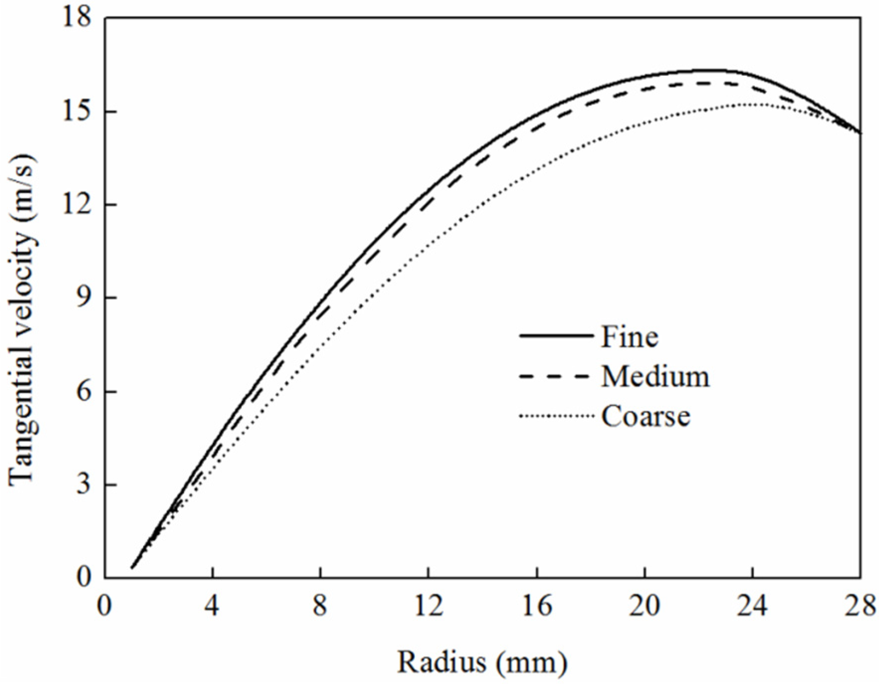
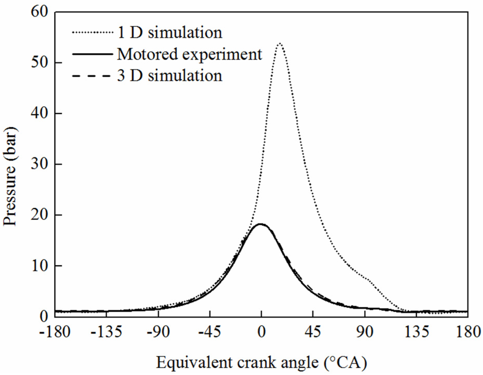
4.3. Model Validation

In order to investigate the mesh independence, two additional meshes are tested for Scheme 2. One with approximately 150,000 cells denoted “coarse” and one with approximately 237,000 cells denoted “medium”. The reference mesh of 304,000 cells is referred to as “fine” [27]. The effect of mesh resolution is presented by comparing the radial profiles of the tangential velocity as shown in Figure 6. The profiles are sampled at the cylinder center cross section when the opposed piston is at the ODC. The comparison shows that the velocity profiles show good agreement and the medium mesh can be considered as the practical mesh.
Figure 6. Comparison between different mesh resolutions.
Energies 08 05866 g006
A simulation running at 20% load of 1200 rpm is performed and a series of comparison validations of the one-dimensional in-cylinder working process, three-dimensional scavenging process and motored conditions were conducted, as shown in Figure 7. The simulation results agree with the experimental results in the scavenging process which indicates that the parameters are reasonably selected.
Figure 7. Comparison between in-cylinder pressures.
Energies 08 05866 g007

5. Simulation Results and Discussion

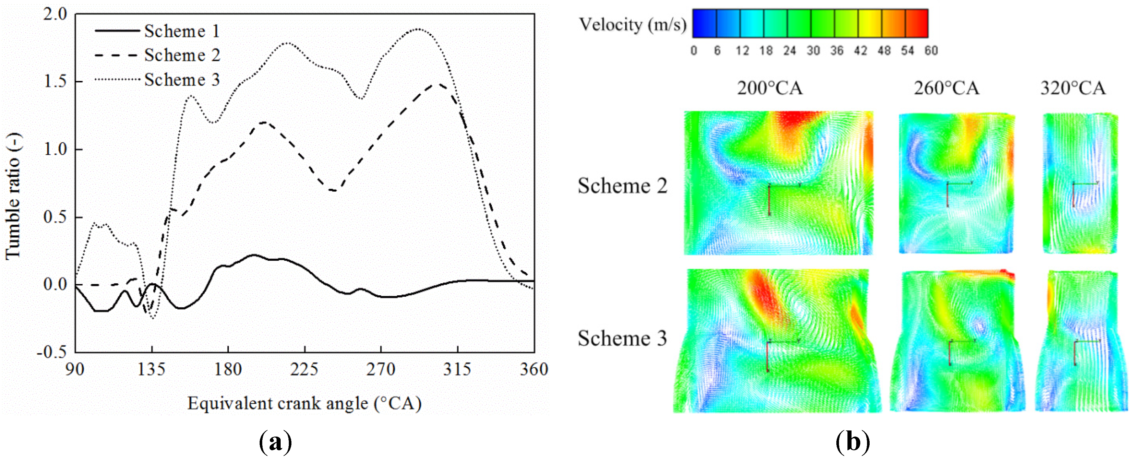
5.1. In-Cylinder Air Motion

In-cylinder flow is divided into a swirl component around the cylinder axis and a tumble component around the vertical cylinder axis, respectively. Figure 8 shows that tumble ratio changes using different scavenging system configurations at an engine speed of 6000 rpm. As shown in Figure 8a, for Schemes 1 and 2, the result shows that tumble is hardly possible in the uniform intake chamber scheme. In contrast, the in-cylinder tumble ratio corresponding to non-uniform intake chamber scheme shows a rising tendency throughout the initial phases of scavenging process and compression process, reaching its maximum value at 200 °CA and 310 °CA, respectively, while in the later phases of scavenging and compression process, the tumble ratio decreases due to tumble vortex crushing. As shown in Figure 8b for Schemes 2 and 3, two approaches can be adopted to organize tumble by the non-uniform intake chamber scheme and using different piston crown shapes. This simulation carried out a study on the flat piston and pit piston configurations with both using the same scavenging method. In-cylinder tumble changes remain similar in either flat and pit piston and the tumble ratio in Scheme 2 exceeds that in Scheme 1. Due to an earlier opening of exhaust ports corresponding to pit piston and the flow-guiding effect of the exhaust piston pit design, in-cylinder tumble ratio in Scheme 2 is bigger during the initial exhaust phase in which non-uniform exhaust plays the main role in tumble organization. As scavenging proceeds, the non-uniform intake chamber and flow-guiding effect generated by the intake piston pit intensify the tumble and tumble ratio increases accordingly. During the post-scavenging period after ODC, as in-cylinder air velocity reduces the in-cylinder tumble drops, reaching its minimum value at intake port closing. Due to the inertia effect caused by air motion and the directional organization of opposed pistons on in-cylinder flow, in-cylinder tumble ratio increases. As a result, tumble ratio in Scheme 2 exceeds that in Scheme 1. The result also shows that the tumble ratio decreases due to large-scale directional flow crushing in the compression process and tends to be uniform near the inner dead point.
Figure 8. Variation of tumble ratio for different scavenging schemes; (a) Variation of tumble ratio with equivalent crank angle; (b) tumble velocity at different crank angle.
Energies 08 05866 g008
In-cylinder swirl in uniflow scavenging is defined as an in-cylinder flow round the cylinder axis directionally mainly through intake port radial angle. Figure 9a shows that swirl the results of Schemes 1 and 2 show the influence of different intake chamber schemes on swirl ratio at the same intake radial angle: the swirl ratio organized by uniform intake chamber is obviously higher than that produced by a non-uniform intake chamber. The simulation study also proves that a non-uniform intake chamber with a coordinated intake port radial angle can produce inclined-axis tumble. The effect on in-cylinder swirl of different piston crown schemes is shown in Schemes 2 and 3 by the same scavenging chamber method. The result shows that in-cylinder swirl changes tend to be uniform and swirl ratio in Scheme 2 exceeds the value in Scheme 3. Due to an earlier opening of the intake ports for the pit piston, swirl in Scheme 3 forms earlier than in Scheme 2. Meanwhile, the circumferential flow is unevenly distributed, resulting in an increasing tumble momentum and a decreasing swirl momentum. As shown in Figure 9b, the swirl ratio in Scheme 3 is lower than that in Scheme 1 in the scavenging and compression process. After ODC in-cylinder swirl motion slows down at the end of scavenging.
Figure 9. Variation of swirl ratio for different scavenging schemes; (a) Variation of swirl ratio with equivalent crank angle; (b) swirl velocity at different crank angle.
Energies 08 05866 g009
The comparison of squish around IDC for different opposed pistons characterized is shown in Figure 10. Figure 10a shows that the effect of flat piston on in-cylinder radial squish around IDC is small with a radial velocity approaching to zero, visible in Scheme 2. In contrast, Scheme 3 pit piston affects the squish around IDC significantly and the radial velocity is symmetric with respect to IDC. The SOC is at 340 °CA and Figure 10b shows that at SOC the piston crown with pit has a higher in-cylinder radial velocity.
Figure 10. Variation of squish velocity for different piston crown shapes; (a) Variation of squish velocity with equivalent crank angle; (b) squish velocity 20 °CA before IDC.
Energies 08 05866 g010

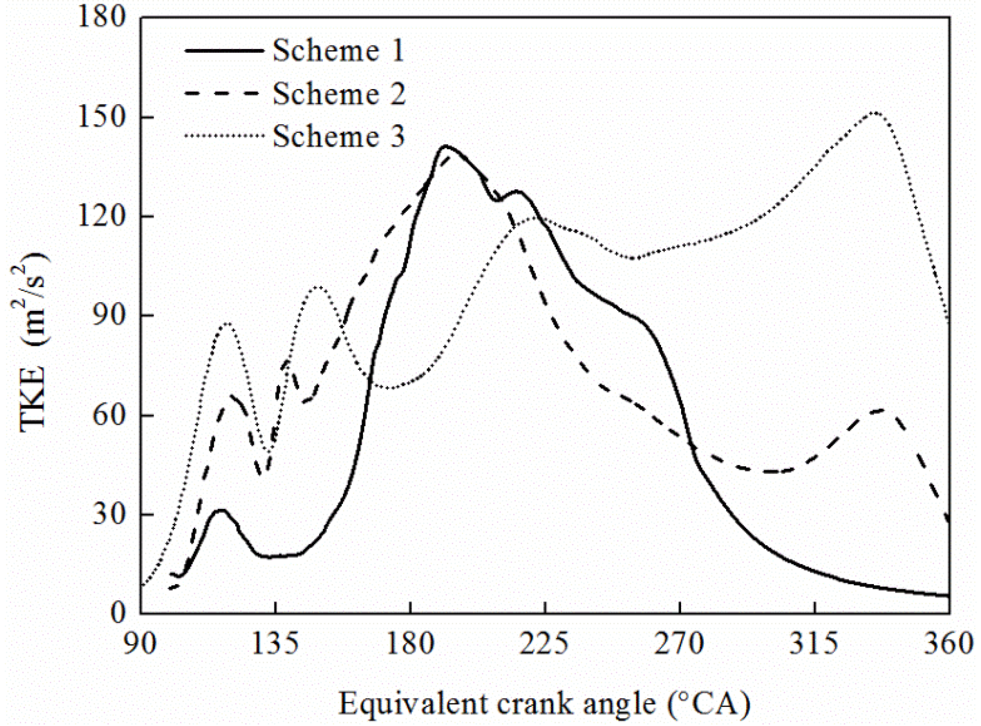
5.2. Turbulence Kinetic Energy

Figure 11 shows that the variation of mean turbulence kinetic energy (TKE) for different scavenging system configurations at an engine speed of 6000 rpm. During the initial phase of the scavenging process, TKE is higher due to a high-frequency turbulence and is maximized around 190 °CA for the non-uniform intake chamber scheme. Though showing a downward trend in the compression process, the TKE decrease rate is small. A relatively small peak value is shown at 340 °CA, owing to high-frequency turbulence produced by tumble crushing, swirl decrease and sustained tumble. In contrast, due to a significant difference between the in-cylinder tumble and swirl components when a uniform intake chamber scheme is adopted, swirl continuously weakens by compression thereupon resulting in a decrease in the TKE level. TKE using non-uniform intake methods is higher than that obtained by uniform intake methods.
Figure 11. Variation of TKE for different scavenging schemes.
Energies 08 05866 g011
The simulation of Schemes 2 and 3 studied flat and pit pistons using the same intake chamber methods for both. The result shows that in-cylinder TKE intensifies in the scavenging process but TKE is lower in the compression process due to tumble shearing and dissipation. At SOC Scheme 3 has the highest TKE, which is 2.5 times higher than in Scheme 2. In the initial scavenging process, the in-cylinder TKE changes of the two schemes tend to be uniform and the TKE value in Scheme 3 exceeds that in Scheme 2, yet the changes in the two schemes diversify after ODC: variance in TKE is small since Scheme 3 is more advantageous than Scheme 2 due to a higher tumble ratio in Scheme 3. The simulation result indicates that during the initial and meta-phases of compression, the crushing and organization of in-cylinder tumble maintain a relatively high-level TKE. In contrast, Scheme 3 promotes the formation of internal tumble and swirl, produces a higher TKE in compression and keeps a rising tendency where squish is organized around IDC. Therefore, it can be concluded that continuous in-cylinder tumble and swirl form a relatively high TKE and an efficient squish motion further enhances TKE.

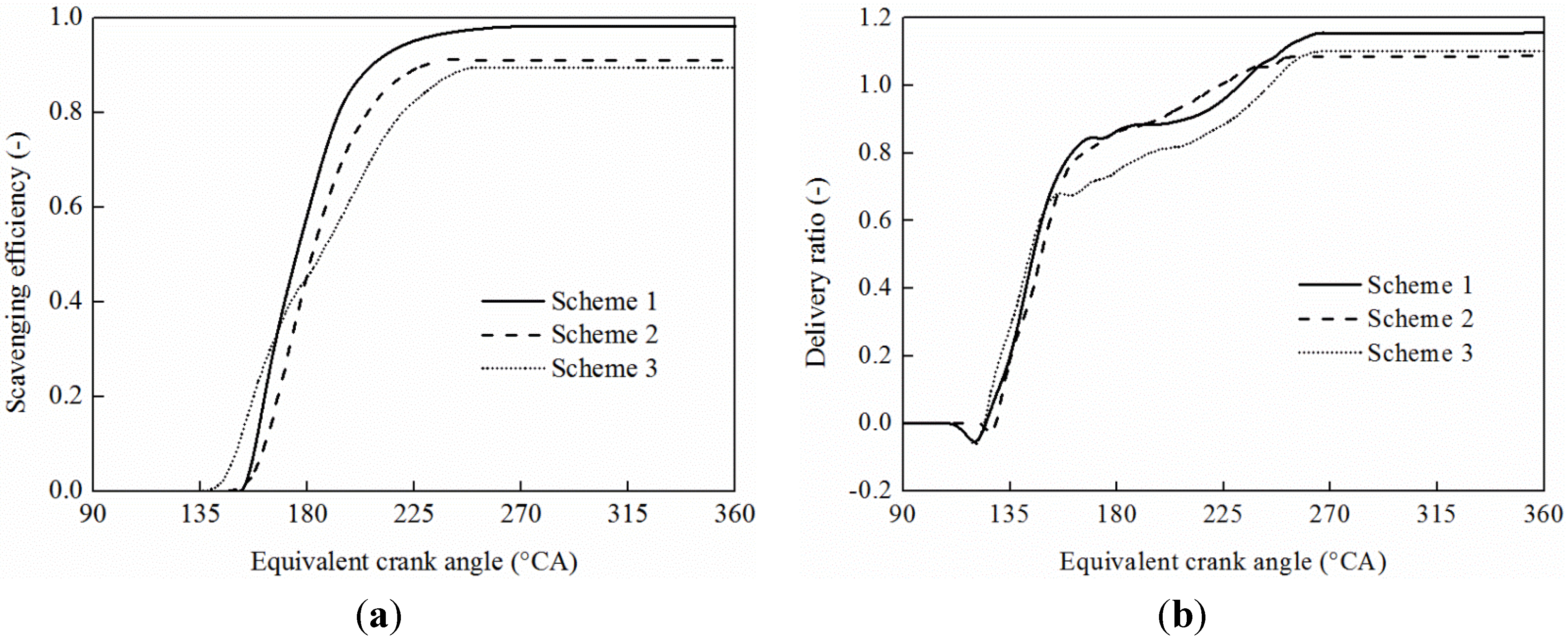
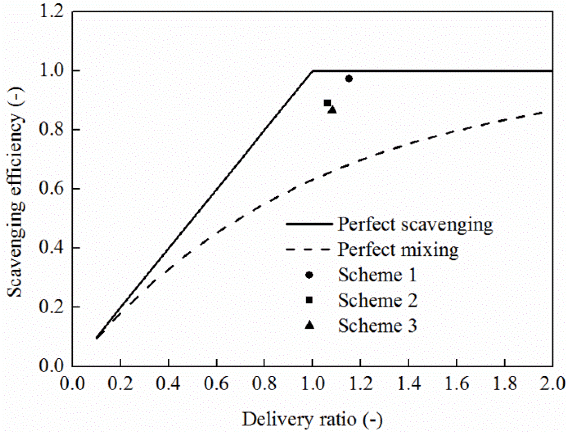
5.3. Scavenging Process

Figure 12 shows that the different scavenging system configurations affect scavenging efficiency and delivery ratio at 6000 rpm.
Figure 12. Variation of scavenging process for different scavenging schemes; (a) Scavenging efficiency; (b) delivery ratio.
Energies 08 05866 g012
Compared with the uniform intake chamber scheme, the scavenging efficiency of the non-uniform intake chamber scheme is lower. During scavenging, the uniform intake chamber scheme can organize a higher swirl and produce a relatively high scavenging efficiency as well by virtue of an extremely low tumble level which avoids the blending of fresh charge and burnt gas. Because of the pit piston structure, Scheme 3 allows an advanced and durable scavenging process compared with Scheme 2. The simulation result also shows that due to the characteristics of flat pistons which have a small influence on swirl, and the in-cylinder tumble is lower. As a result, the scavenging efficiency of Scheme 2 is higher than that of Scheme 3. Conversely, the pit piston design on the one hand aggravates non-uniform intake, but also hinders in-cylinder swirl organization resulting in a relatively lower swirl ratio. Meanwhile, Scheme 3 can promote in-cylinder tumble organization whereby a relatively higher tumble ratio is produced, thus decreasing scavenging efficiency. With respect to scavenging efficiency, the pit piston design is inferior to the flat piston one but similar in delivery ratio. During the meta-phase of the scavenging process, a larger tumble ratio hinders air flow and the delivery ratio is lower, while the delivery ratios of the two schemes tend to be uniform during the later scavenging process.
Delivery ratio, trapping efficiency and scavenging efficiency were usually employed as evaluation index on the two-stroke scavenging system [28]:
The delivery ratio:
l 0 = mass of delivered air (or mixture) per cyclerefer reference mass
The reference mass is defined as displaced volume × ambient air (or mixture). Ambient air (or mixture) density is determined at atmospheric conditions or at intake conditions.
The trapping efficiency:
η tr = mass of delivered air (or mixture) retained mass of delivered air (or mixture)
The trapping efficiency indicates what fraction of the air (or mixture) supplied to the cylinder is retained in the cylinder.
The scavenging efficiency:
η sc = mass of delivered air (or mixture) retained mass of trapped cylinder charge
The scavenging efficiency indicates to what extent the residual gases in the cylinder have been replaced with fresh air. When the reference mass in the definition of delivery ratio is the trapped cylinder mass (or closely approximated by it) then:
η sc = l 0 η tr
For the perfect scavenging model, trapping and scavenging efficiency vary with delivery ratio as follows:
η tr = 1 η sc = l 0 for  l 0 1 η tr = 1 / l 0 η sc = 1 for  l 0 > 1
For the perfect mixing model, trapping and scavenging efficiency vary with delivery ratio as follows:
η tr = 1 l 0 ( 1 e l 0 ) η sc = 1 e l 0
As shown in Figure 13, by comparing the scavenging data of the three schemes with the results in reference [28], scavenging efficiency and delivery ratio of three schemes fall in between perfect scavenging and perfect mixing.
Figure 13. Comparison of the three scavenging schemes.
Energies 08 05866 g013

6. Conclusions

The important conclusions derived from the simulation of in-cylinder air motion in an OP2S engine with different scavenging system configurations can be summarized as follows:
(1)
The coincidence of the 3D calculation results with the theoretical-interpretative results of the 0D model manifests the veracity of this approach.
(2)
The swirl ratio organized by uniform intake chamber is obviously higher than that obtained by a non-uniform intake chamber, while the non-uniform intake chamber can organize inclined-axis tumble, which increases TKE around IDC.
(3)
For the non-uniform intake chamber, the pit piston scheme is more beneficial to tumble vortex formation compared to all other scavenging schemes, with a maximum tumble ratio improvement of about 26% over the flat piston scheme.
(4)
At 340 °CA, CFD results show that there is an increase in TKE of about 150% for a pit piston compared to that of a flat piston, which is due to squish effect of the pit piston. The uniform intake chamber scheme is not beneficial to the tumble vortex formation and the TKE is minimum before IDC.
(5)
The scavenging efficiency and delivery ratio are higher for the uniform intake chamber scheme. It is concluded that a pit piston non-uniform scavenging chamber is a better choice to have good tumble ratio and TKE, but a flat piston uniform scavenging chamber is a better choice to have good swirl ratio, scavenging efficiency and delivery ratio.

Acknowledgments

The authors gratefully acknowledge the financial support by the foundation research funds of Ministry of Industry and Information Technology of the People’s Republic of China.

Author Contributions

Fukang Ma and Changlu Zhao designed the simulation scheme; Fukang Ma and Zhenfeng Zhao performed the simulations; Zhenfeng Zhao and Shuanlu Zhang analyzed the data; and Fukang Ma and Fujun Zhang contributed to the editing and reviewing of the document.

Conflicts of Interest

The authors declare no conflict of interest.

Nomenclature

0Dzero-dimensional m number of intake port
1Dmono-dimensional n engine speed
3Dthree-dimensionalODCouter dead center
A squish squish compression areaOP2Sopposed-piston two-stroke
CFDcomputational fluid dynamicsPIVparticle image velocimetry
d h s / d t relative velocity of the opposed pistons p z in-cylinder gas pressure
EPOexhaust port opening R gas constant
F s area of intake port in different crank angle r T radius of tumble vortex
GDIgasoline direct injectionSOCstart of combustion
ggravitational acceleration T gas temperature
h distance between the opposed pistonsTDCtop dead center
h I P C half distance between the opposed pistons at IPC V P relative velocity of the opposed pistons before IDC
h c half distance between the opposed pistons in compression process V squish squish velocity
h s instantaneous squish height v i n instantaneous flow velocity of intake ports
I fluid vortex inertia v i n _ i instantaneous flow velocity of every intake ports
I c fluid vortex inertia in compression process v i n _ i _ x vectorial sum of the X axial component
I I P C the fluid vortex inertia at IPC v i n _ i _ y vectorial sum of the Y axial component
IDCinner dead center v T _ c tumble velocity in compression process
ICignition combustion v T _ I P C the tumble velocity at IPC
IPCintake ports closing v T _ s the tumble velocity
J angular momentum v x the X axial component
J I P C inertia angular momentum at IPC v y the Y axial component
K 1 proportionality coefficient ω T angular velocity of the equivalent rotating solid body
K 2 ratio of squish compression area to cylinder cross section area μ s intake port flow coefficient
k adiabatic exponentϕcrank angle

References

  1. Pirault, J.P.; Flint, M. Opposed Piston Engines: Evolution, Use, and Future Applications; SAE International: Warrendale, PA, USA, 2010. [Google Scholar]
  2. Naik, S.; Johnson, D.; Koszewnik, J. Practical Applications of Opposed-Piston Engine Technology to Reduce Fuel Consumption and Emissions; SAE Technical Paper 2013-01-2754; SAE International: Warrendale, PA, USA, 2013. [Google Scholar]
  3. Hofbauer, P. Opposed Piston Opposed Cylinder (OPOC) Engine for Military Ground Vehicles; SAE Technical Paper 2005-01-1548; SAE International: Warrendale, PA, USA, 2005. [Google Scholar]
  4. Hirsch, N.R.; Schwarz, E.E.; McGough, M.G. Advanced Opposed-Piston Two-Stroke Diesel Demonstrator; SAE Technical Paper 2006-01-0926; SAE International: Warrendale, PA, USA, 2006. [Google Scholar]
  5. Herold, R.E.; Wahl, M.H.; Regner, G. Thermodynamic Benefits of Opposed-Piston Two-Stroke Engines; SAE Technical Paper 2011-01-2216; SAE International: Warrendale, PA, USA, 2011. [Google Scholar]
  6. Regner, G.; Herold, R.E.; Wahl, M.H. The Achates Power Opposed-Piston Two-Stroke Engine: Performance and Emissions Results in a Medium-Duty Application; SAE Technical Paper 2011-01-2221; SAE International: Warrendale, PA, USA, 2011. [Google Scholar]
  7. Redon, F.; Kalebjian, C.; Kessler, J. Meeting Stringent 2025 Emissions and Fuel Efficiency Regulations with an Opposed-Piston, Light-Duty Diesel Engine; SAE Technical Paper 2014-01-1187; SAE International: Warrendale, PA, USA, 2014. [Google Scholar]
  8. Regner, G.; Johnson, D.; Koszewnik, J. Modernizing the Opposed Piston, Two-Stroke Engine for Clean, Efficient Transportation; SAE Technical Paper 2013-26-0114; SAE International: Warrendale, PA, USA, 2013. [Google Scholar]
  9. Zhao, F.; Lai, M.C.; Harrington, D.L. Automotive spark-ignited direct-injection gasoline engines. Prog. Energy Combust. Sci. 1999, 25, 437–562. [Google Scholar] [CrossRef]
  10. Arcoumanis, C.; Bae, C.S.; Hu, Z. Flow and Combustion in a Fourvalve, Spark-Ignition Optical Engines; SAE Paper 940475; SAE International: Warrendale, PA, USA, 1994. [Google Scholar]
  11. Fan, L.; Reitz, R.D.; Trigui, N. Intake Flow Simulation and Comparison with PTV Measurements; SAE Technical Paper 1999-01-0176; SAE International: Warrendale, PA, USA, 1999. [Google Scholar]
  12. Ismail, H.M.; Ng, H.K.; Gan, S. Evaluation of non-premixed combustion and fuel spray models for in-cylinder diesel engine simulation. Appl. Energy 2012, 90, 271–279. [Google Scholar] [CrossRef]
  13. Mikalsen, R.; Roskilly, A.P. A computational study of free-piston diesel engine combustion. Appl. Energy 2009, 86, 1136–1143. [Google Scholar] [CrossRef]
  14. Rakopoulos, C.D.; Kosmadakis, G.M.; Dimaratos, A.M. Investigating the effect of crevice flow on internal combustion engines using a new simple crevice model implemented in a CFD code. Appl. Energy 2011, 88, 111–126. [Google Scholar] [CrossRef]
  15. Jia, M.; Xie, M.Z.; Wang, T.Y. The effect of injection timing and intake valve close timing on performance and emissions of diesel PCCI engine with a full engine cycle simulation. Appl. Energy 2011, 88, 2967–2975. [Google Scholar] [CrossRef]
  16. Micklow, G.J.; Gong, W.D. Intake and in-cylinder flow field modeling of a four valve diesel engine. Proc. Mech. Int. J. Automob. Eng. 2007, 221, 1425–1440. [Google Scholar] [CrossRef]
  17. Nordgren, H.; Hildingsson, L.; Johansson, B. Comparison between In-Cylinder Measurements, CFD Simulations and Steady Flow Impulse Torque Swirl Meter Measurements; SAE Technical Paper 2003-01-3147; SAE International: Warrendale, PA, USA, 2003. [Google Scholar]
  18. Sweetland, P.; Reitz, R.D. Particle Image Velocimetry Measurements in the Piston Bowl of a DI Diesel Engine; SAE Technical Paper 940283; SAE International: Warrendale, PA, USA, 1994. [Google Scholar]
  19. Gunasekaran, E.J.; Ganesan, V. Simulation of Fuel-Air Interaction in a Four Stroke Four Valve Direct Injected Spark Ignition Engine; SAE Technical Paper 2007-01-0153; SAE International: Warrendale, PA, USA, 2007. [Google Scholar]
  20. Rakopoulos, C.D.; Kosmadakis, G.M.; Pariotis, E.G. Investigation of piston bowl geometry and speed effects in a motored HSDI diesel engine using a CFD against a quasi-dimensional model. Energy Convers Manag. 2010, 51, 470–484. [Google Scholar] [CrossRef]
  21. Lin, L.; Shulin, D.; Jin, X. Effects of Combustion Chamber Geometry on In-Cylinder Air Motion and Performance in DI Diesel Engine; SAE technical paper 2000-01-0510; SAE International: Warrendale, PA, USA, 2000. [Google Scholar]
  22. Shimoda, M.; Shigemori, M.; Tsuruoka, S. Effect of Combustion Chamber Configuration on In-Cylinder Air Motion and Combustion Characteristics of DI Diesel Engine; SAE Technical Paper 850070; SAE International: Warrendale, PA, USA, 1985. [Google Scholar]
  23. Dolak, J.G.; Shi, Y.; Reitz, R.D. A Computational Investigation of Stepped-Bowl Piston Geometry for a Light Duty Engine Operating at Low Load; SAE Technical Paper 2010-01-1263; SAE International: Warrendale, PA, USA, 2010. [Google Scholar]
  24. Falfari, S.; Brusiani, F.; Bianchi, G.M. Assessment of the Influence of Intake Duct Geometrical Parameters on the Tumble Motion Generation in a Small Gasoline Engine; SAE Technical Paper 2012-32-0095; SAE International: Warrendale, PA, USA, 2012. [Google Scholar]
  25. Falfari, S.; Brusiani, F.; Bianchi, G.M. Numerical analysis of in-cylinder tumble flow structures-parametric 0D model development. Energy Procedia 2014, 45, 987–996. [Google Scholar] [CrossRef]
  26. Ramajo, D.; Zanotti, A.; Nigro, N. Assessment of a zero-dimensional model of tumble in four-valve high performance engine. Int. J. Numer. Methods Heat Fluid Flow 2007, 17, 770–787. [Google Scholar] [CrossRef]
  27. Sigurdsson, E.; Ingvorsen, K.M.; Jensen, M.V. Numerical analysis of the scavenge flow and convective heat transfer in large two-stroke marine diesel engines. Appl. Energy 2014, 123, 37–46. [Google Scholar] [CrossRef]
  28. Taylor, C.F. The Internal-Combustion Engine in Theory and Practice: Thermodynamics, Fluid Flow, Performance, 2nd ed.; MIT Press: Cambridge, UK, 1985; Volume 1, p. 584. [Google Scholar]

