Article

Improved Performance of Electrical Transmission Tower Structure Using Connected Foundation in Soft Ground

1
School of Civil and Environmental Engineering, Yonsei University, 134 Shinchon-dong, Seodaemun-gu, Seoul 120-749, Korea
2
KTP Consultants Pte Ltd., E-Centre@Redhill, 3791 Jalan Bukit Merah, Singapore 159471, Singapore
*
Author to whom correspondence should be addressed.
Energies 2015, 8(6), 4963-4982; https://doi.org/10.3390/en8064963
Submission received: 17 February 2015 / Revised: 12 May 2015 / Accepted: 20 May 2015 / Published: 28 May 2015
(This article belongs to the Special Issue Resilience of Energy Systems)

Abstract

:
A connected foundation is an effective foundation type that can improve the structural performance of electrical transmission towers in soft ground as a resilient energy supply system with improved stability. In the present study, the performance of a connected foundation for transmission towers was investigated, focusing on the effect of connection beam properties and soil conditions. For this purpose, a finite element analysis was performed for various foundation and soil conditions. In order to validate the finite element analysis, the calculated results were compared with measured results obtained from field load tests. The use of connection beams was more effective for uplift foundations that usually control the design of transmission tower foundations. For the effect of soil condition, the use of connected foundation is more effective in soft clays with lower undrained shear strength (su). Smaller amounts of differential settlement were observed in all soil conditions for both unconnected and connected foundations when a bearing rock layer was present. When the foundation was not reinforced by connection beams, the values of lateral load capacity of tower structure (Hu) were similar for both with- and without-rock layers. It was confirmed that introducing haunch-shaped connection beams is effective for increasing connection beam stability.

1. Introduction

For the electrical transmission system, transmission towers are often installed with certain foundations that support the upper tower structure and associated overhead power lines. The transmission tower structures are subjected to various unexpected damages from a wide range of extreme weather events, including hurricanes, tornadoes, snow, and ice storms, and human disasters such as terrorism [1,2,3]. In particular, as climate change has been an issue in various social and engineering fields, it has become important to prepare a resilient infrastructure system that can guarantee or improve the stability of the energy supply system [4,5,6]. For the subsurface soil zone where the foundations of transmission towers are embedded, the issue of climate change also needs to be addressed for both design and construction of the structures. Increasing freezing-thawing cycles within the soil zone cause changes in various soil properties such as permeability, volume change behavior, strength, and compressibility [7,8,9]. Unusual fluctuation of groundwater level due to changes in annual precipitation characteristics causes additional settlements and unexpected reduction in the bearing capability of foundations [10,11,12]. All these threaten the stability and sustainability of the electrical transmission tower system, highlighting the need for a more robust and resilient structural system with certain reinforcements.
The types of tower foundation often used are pile, pier, inverted T-type, and mat foundation [13,14,15,16]. The inverted T-type foundation is widely used in transmission towers and can be used for small load conditions in good quality soils composed of sand. The pier foundation can be used in steep grade or deep bearing strata. This foundation is effective to support large loads of transmission towers and is frequently used for Ultra High Voltage (UHV) transmission towers. Pile foundation is generally used in weak soils, such as clay and reclaim soil, and often suffers structural damage and geotechnical instability due to insufficient foundation resistance and large differential settlements [14,15,17].
The size of transmission towers increases with electricity demand; the foundation size also increases to efficiently support the larger transmission towers. A foundation reinforced with additional structures is often used to improve foundation performance. For example, various researchers proposed setting rock bolt on a pier foundation to reduce settlement and to increase the resistance of the foundation; and setting a protective slab under the tower foundation to reduce the differential settlement of the foundation [18,19,20].
TEPCO [21] and IEEE [13] proposed the use of connection beams placed between the individual tower foundation components. According to TEPCO [21], the increase in load capacity for a foundation reinforced with a connection beam can be estimated based on the mobilized shear stresses and bending moments due to the weight of the connection beam. In the IEEE [13], a general description of the use of connection beams is presented with emphasis on the reduction effect of differential settlements. The significant effects of connection beams were investigated by Kyung et al. [22]. They performed small-scale model tests and finite element analyses in a clay condition and found that a 25% relative stiffness of the connection beams to that of the mat foundation is most effective to improve foundation performance.
All these results were obtained for certain assumed soil and foundation conditions. There were no changes in soil conditions such as strength and compressibility, which were indicating limited condition of the application. As a connected foundation can be more effectively used in soft, clayey soil, it is important to check any possible effect of soil and foundation conditions on variation in mechanical performance.
In the present study, the effects of a connected foundation on the performance of transmission tower structures were investigated with consideration of different types of connection beam and various soil conditions. Soft clay conditions with and without a bearing rock layer were assessed as well. For this purpose, a series of finite element analyses were performed and used to analyze the effects of a connected foundation. A large-scale field load test using a prototype model structure was performed and compared with the results from the finite element analyses. Improved performance of transmission tower structures was analyzed in detail for various connection beam stiffness and soil conditions.

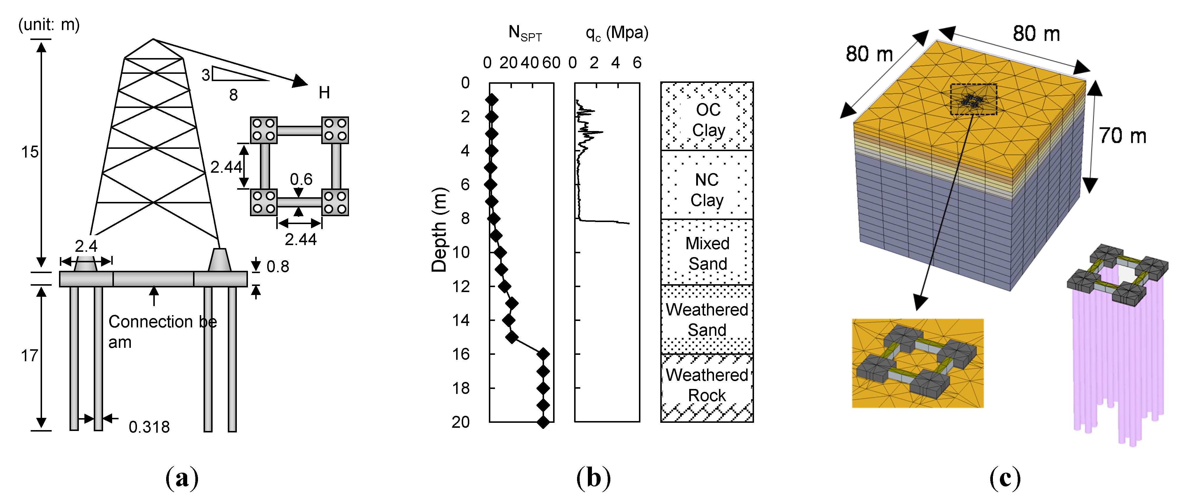
2. Transmission Tower Foundation

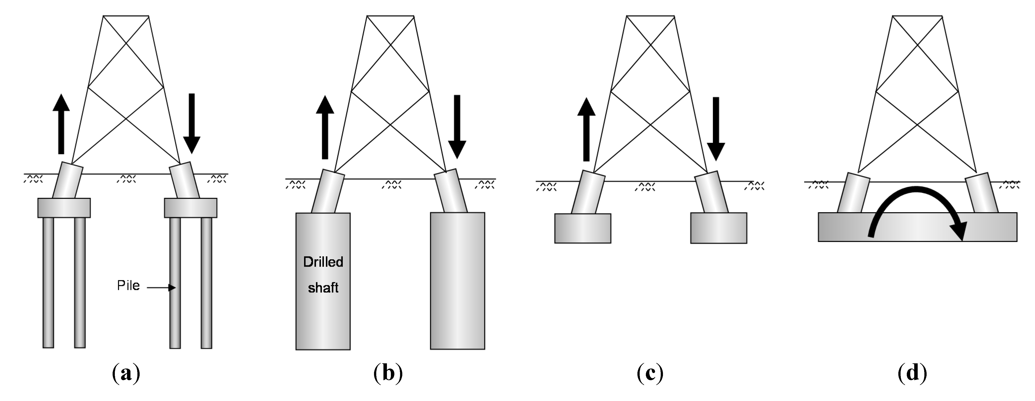
2.1. Foundation Types and Design Procedure

A transmission tower structural system consists of overhead power lines, steel lattice tower structures, and foundations. The foundations are generally installed at the four corners of the tower structure. The foundations of transmission towers can be classified as axial load foundations and moment load foundations. Axial load foundations indicate the cases where lateral load acting on a tower would be transferred as uplift and compressive loads on the individual foundations at each corner. Pile foundations, pier foundations, and inverted T foundations, shown in Figure 1a to c, are considered as axial load foundations, which are effective in resisting lateral tower loads but vulnerable to differential settlements. A mat foundation, shown in Figure 1d, is a moment-load foundation, which is effective in preventing structural damage from differential settlements, while the lateral resistance tends to be lower than that of axial load foundations.
Figure 1. Types of transmission tower foundations: (a) pile foundation; (b) pier foundation; (c) inverted-T foundation; and (d) mat foundation.
Energies 08 04963 g001
The type of transmission tower foundation used is determined based on soil conditions. A pile foundation is generally used in soft soil conditions. For stability analysis, the load capacity of an individual foundation is evaluated for a given soil condition, ensuring that the load capacity is greater than the design load. Figure 2 shows the typical configuration of loads and resistances for a transmission tower structure where an applied lateral load on a tower (H), transferred loads to lower foundations (Q), and mobilized foundation resistances (R) are indicated. The lateral load (H) acting on a tower is transferred to the lower foundations of the front compressive and rear uplift sides. The transferred loads are composed of the vertical (Qvc and Qvt) and horizontal (Qhc and Qht) load components, as indicated in Figure 2. The magnitude of each load component can be calculated from the geometric characteristics of the transmission tower. The stability of a transmission tower foundation is then determined as follows [21,23]:
Q v c R v c , m = R v c F S  and  Q v t R v t , m = R v t F S
Q h c R h c , m = R h c F S  and  Q h t R h t , m = R h t F S ,
where Qvc and Qvt = transferred compressive and uplift tensile loads on the front and rear sides; Qhc and Qht = transferred horizontal loads on the front and rear sides; Rvc,m and Rvt,m = allowable compressive and uplift resistances; Rhc,m and Rht,m = allowable horizontal front and rear resistances; Rvc, Rvt, Rhc, and Rht = ultimate compressive, uplift, and horizontal front and rear resistances; and FS = factor of safety. While stabilities for both vertical and horizontal loads must be guaranteed, the vertical stability against uplift load (Qvt) frequently controls the design, as uplift resistance is usually smaller than vertical compressive resistance.
Figure 2. Configurations of loads and resistances for transmission tower structure.
Energies 08 04963 g002

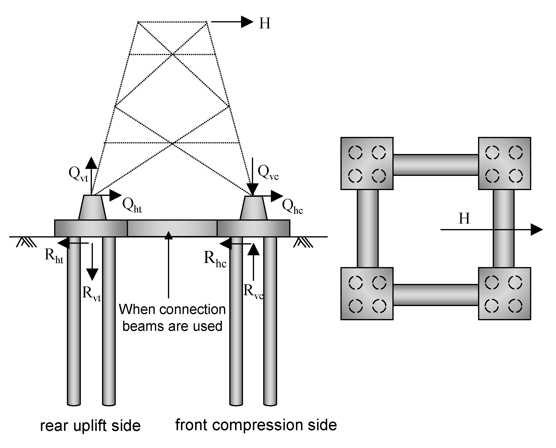
2.2. Connected Foundation

When lateral loads act on the upper transmission tower, the lower foundations at the corners are subject to uplift and compressive loads. This indicates that a larger amount of differential settlement could occur due to the opposite directions of induced settlements at the uplift and compressive sides, which may cause structural damage to the entire transmission tower structure system. Modified foundations reinforced using additional structural components are an option to reduce differential settlement and improve the performance of a foundation. For example, Yang et al. [24] and Wang et al. [25] presented connected H-shaped girders to prevent instability in transmission towers. Yuan et al. [20] also presented tower foundations with protective slabs in order to reduce differential settlement.
A connected foundation is a type of reinforced foundation using connection beams placed between foundations, as illustrated in Figure 2. The design guidelines and performance analysis of connected foundations can be found in TEPCO [21], IEEE [13], and Kyung et al. [22]. According to TEPCO [21], connection beams are regarded as rigid components; their mechanical properties are not considered in the design. IEEE [13] also referred to the use of connection beams for the same purpose of increasing foundation resistance and reducing differential settlements. Kyung et al. [22] analyzed the performance of connected foundations for different structural and load conditions. It should be noted that all these investigations were performed on the limited soil and foundation conditions available in the experimental testing program. Further investigation is warranted to examine the detailed performance of connected foundations in different foundation and soil conditions.

3. Finite Element Analysis

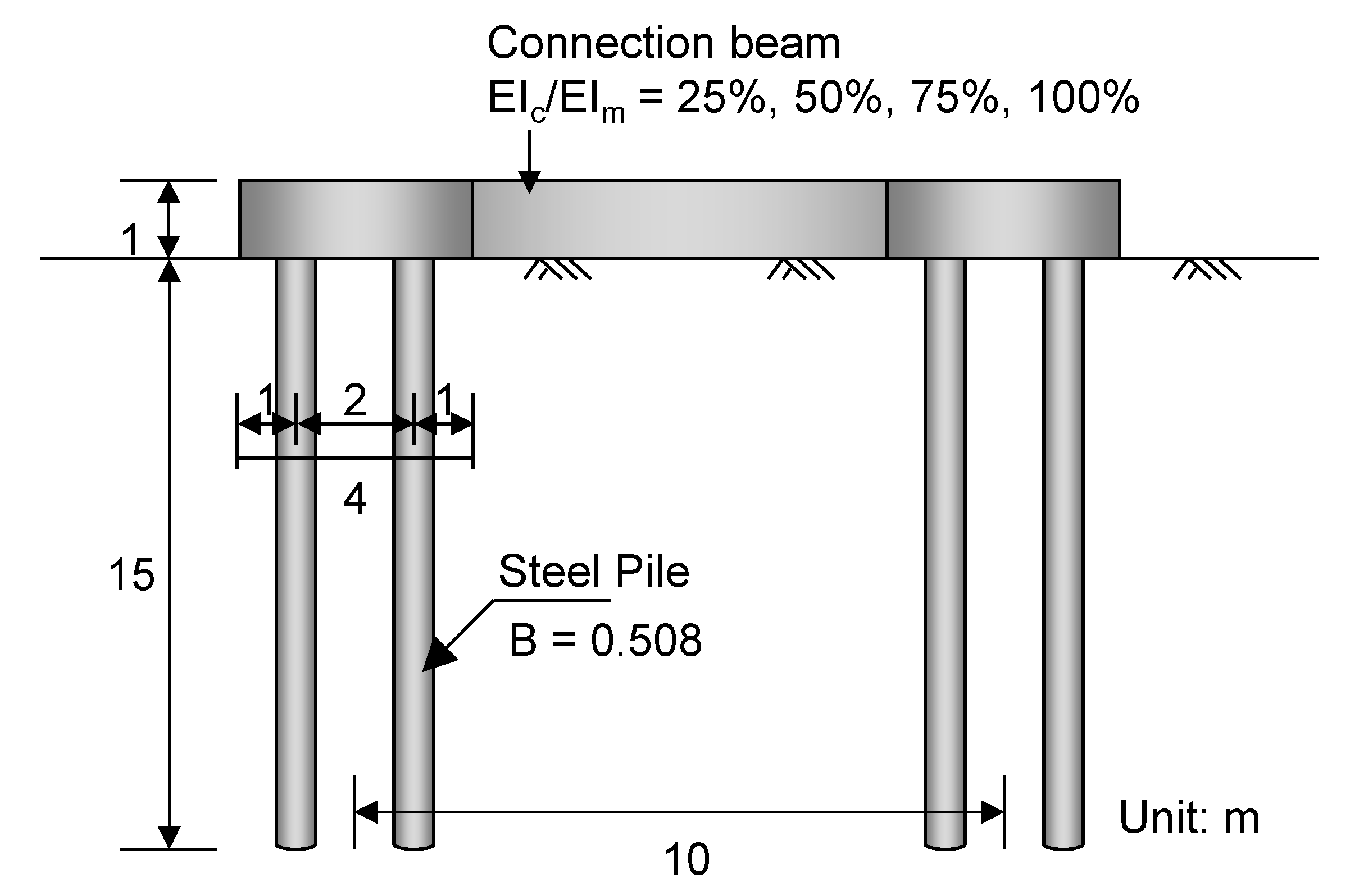
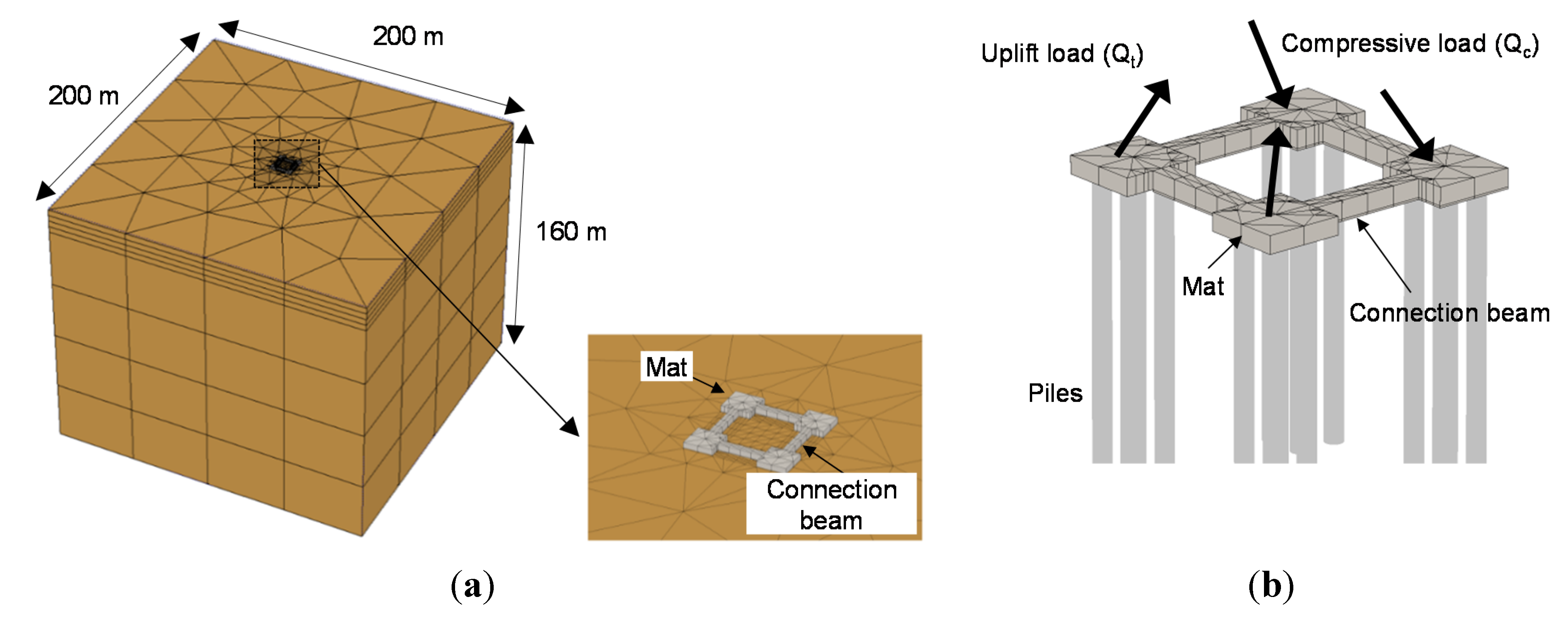
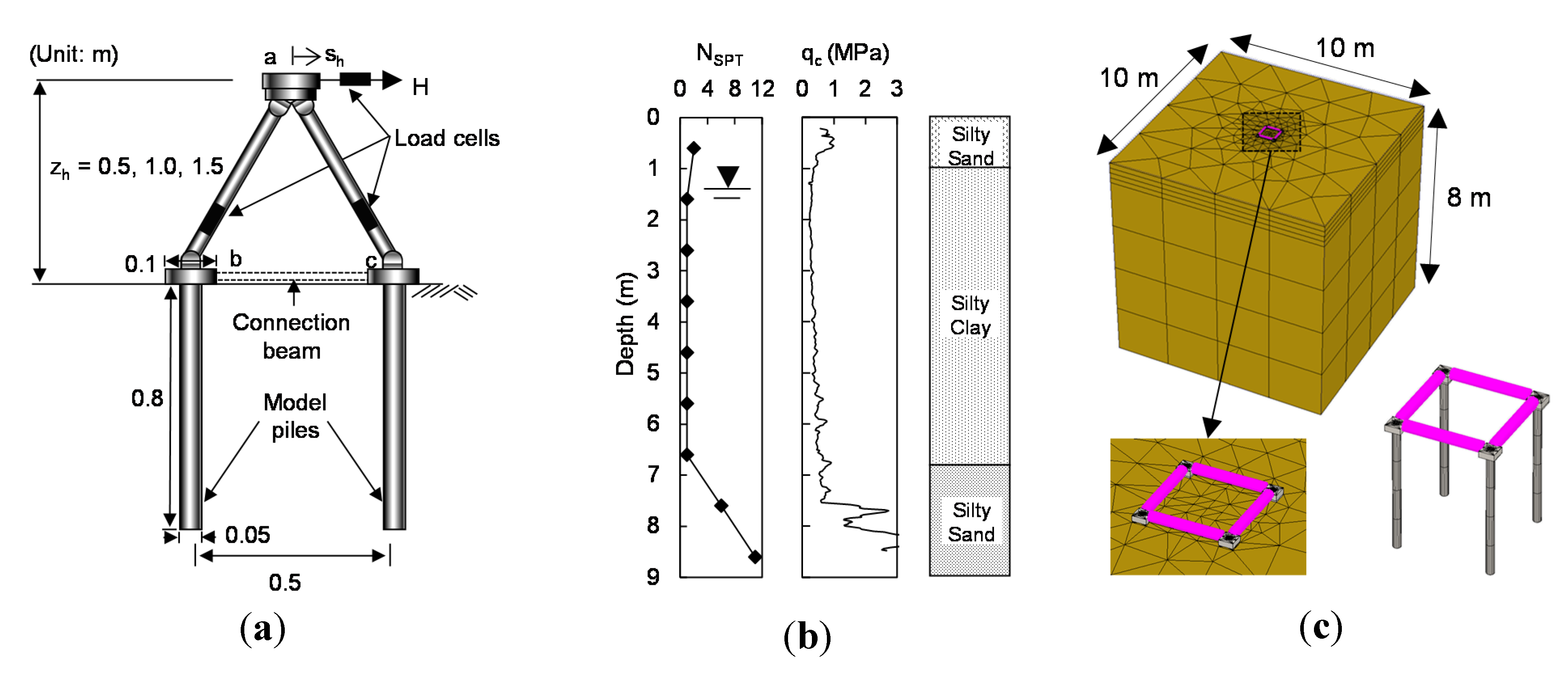
3.1. Description of Analysis

Full-scale model tests of foundations for transmission towers are difficult due to the great expense and effort required in constructing test models and conducting field load tests. For this reason, numerical modeling and analysis are often introduced as an alternative. In the present study, the finite element (FE) analysis of foundations for full-scale transmission tower structures was performed to analyze the behavior and improved performance of foundations reinforced with connection beams. The PLAXIS 3D Foundation [26] was used in the study, which is a widely used finite element analysis program for geotechnical engineering.
Figure 3. Configuration of foundation parts for finite element analysis.
Energies 08 04963 g003
The finite element analyses were planned and prepared based on the typical size and configuration of 345 kV transmission tower structures. Figure 3 shows the configuration of transmission tower foundation considered in the finite element analyses. As shown in Figure 3, the foundation parts are placed at the four sides of the transmission tower, and the foundation at each side consists of a mat and four piles. The width and height of the mat are 4 and 1 m, respectively, and the distance between the foundation sides is 10 m. The diameter and length of the piles are 0.508 and 15 m, respectively, and the pile-to-pile spacing equals 2.7 m.
Four different sizes of connection beams were considered in the analyses, as the rigidity of connection beam varies with its size and affects the effectiveness of connection beams. While the height of the connection beams was always 1 m, different widths of connection beams equal to 25%, 50%, 75%, and 100% of the mat width were considered. The material properties of the connection beams were the same as those of the mat with an elastic modulus (E) and Poisson’s ratio (υ) of 40 GPa and 0.2, respectively. This means that the flexural stiffness of the connection beams (EI) was equal to 25%, 50%, 75%, and 100% of the mat EI. The height of the tower structure was 27 m, and the transferred loads on the foundations were determined from the geometric condition of the transmission tower and foundations when the lateral load (H) was applied on the top of the tower structure.
Figure 4. Finite element model for transmission tower foundation: (a) configuration of connected foundation model and (b) configuration of applied loads.
Energies 08 04963 g004
Figure 4 shows the finite element model prepared in this study. The width and depth of the finite element model in this study were 200 and 160 m, respectively, corresponding to a size larger than 10 times the pile length or 23 times the mat width. According to Liang et al. [27], this represents a sufficiently larger model size to avoid the boundary effect. Finer mesh was used in the zone near the model structure where higher stress concentration was expected. Fixed-end boundary conditions were set along the lateral and bottom sides of the mesh. Mat foundations were assumed to be linear-elastic concrete material, as described previously. Piles were regarded as linear-elastic steel piles with an elastic modulus (E) and Poisson’s ratio (υ) equal to 205 GPa and 0.3, respectively. The interface elements were used between the soil and the pile surfaces, which allowed elastic small displacements and plastic slip behaviors. The shear strength of the interface element was defined based on the strength reduction factor Rint [26], which is given by the following relationships:
c int = R int c s o i l
tan ϕ int = R int tan ϕ s o i l .
where cint and ϕint = cohesion and friction angle of interface; and csoil and ϕsoil = cohesion and friction angle of soil materials; and Rint = reduction factor. The value of Rint was set to 0.4, as obtained from the model load test results that will be further described in Section 3.3. Figure 4b shows the detailed configuration of the applied loads on the foundations at corners. With lateral load acting on the tower, the two front-side foundations are subjected to compressive loads and the other two rear-side foundations are subjected to uplift loads.

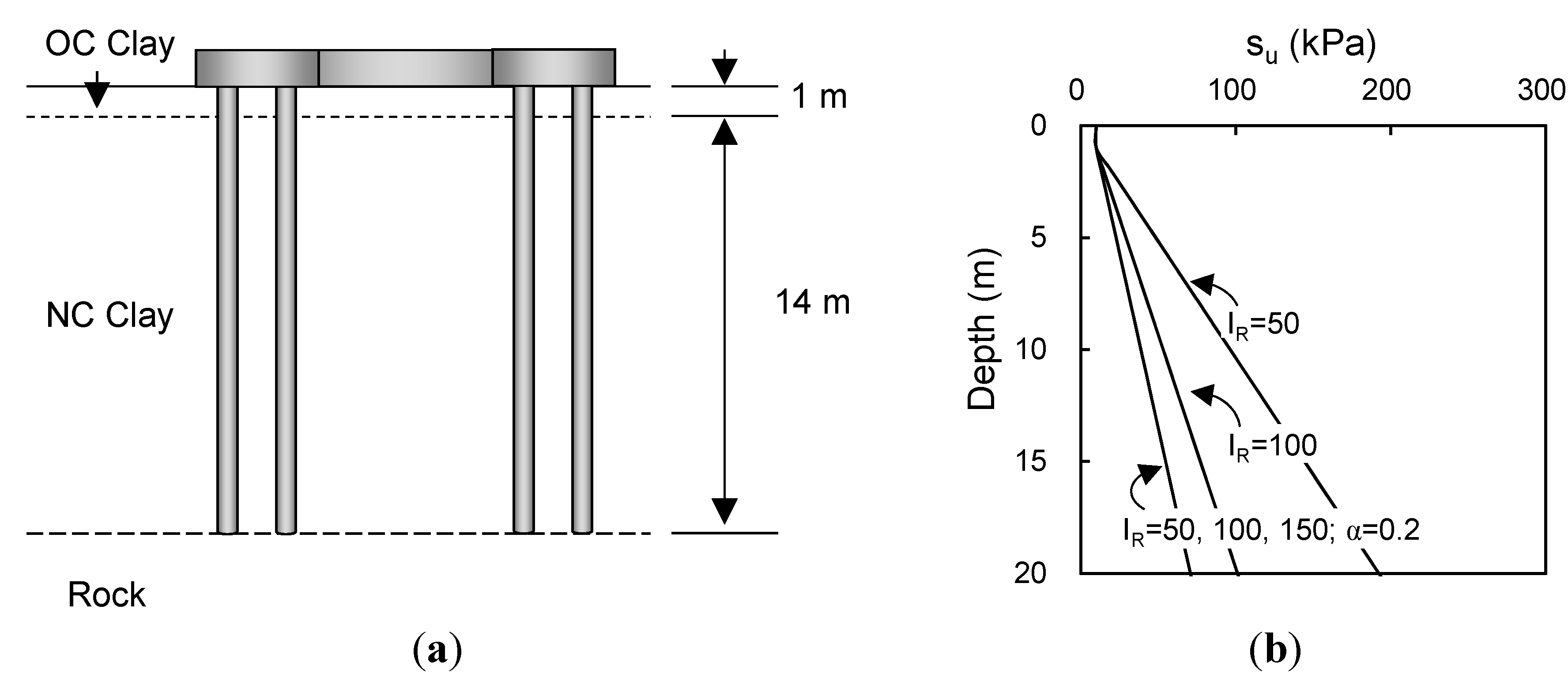
3.2. Soil Conditions

Various clay soil conditions were considered in the finite element analyses. Figure 5 shows the soil profiles considered in the finite element analyses. The soil conditions considered were a soft clay deposit with a lightly over-consolidated (OC) layer near the surface, as is commonly encountered in practice. Below the surface layer, soils were all assumed to be normally consolidated (NC) clay. Other cases with a bearing rock layer at the pile base level, as indicated in Figure 5a, were also considered in the finite element analyses. The unit weight (γsat) of clay was equal to 16 kN/m3 with a Poisson’s ratio (υ) of 0.495 assuming undrained condition. For the NC clay condition, the undrained shear strength (su) varied linearly with depth given as follows:
s u = α γ z
where α = strength increase ratio; z = depth; and γ’ = effective unit weight. The values of su within the OC zone near the surface were assumed to be 10 kPa. α is the ratio of su to the vertical effective stress (i.e., γ’·z). The value of α for most clays ranges from 0.2 to 0.4 [28,29,30,31,32]. In the present study, the value of α was set to 0.2, assuming a soft clay condition.
Figure 5. Soil conditions for finite element analysis: (a) soil layer condition and (b) depth profile of considered soil condition.
Energies 08 04963 g005
The rigidity index is often used to characterize the mechanical state of clay and is defined as the ratio of shear modulus (G) to su given by:
I R = G s u = E s 2 ( 1 + ν u ) s u = E s 3 s u
where G = shear modulus; Es = elastic modulus; and υu = Poisson’s ratio for undrained condition = 0.5. Three different values of IR equal to 50, 100, and 150 were considered in the analyses. Figure 5b shows the profiles of soil conditions considered in the finite element analyses. For the cases with a bearing rock layer, the values of E and υ for rock were 50 MPa and 0.15, respectively, which represent the conditions of weathered rock [33,34].

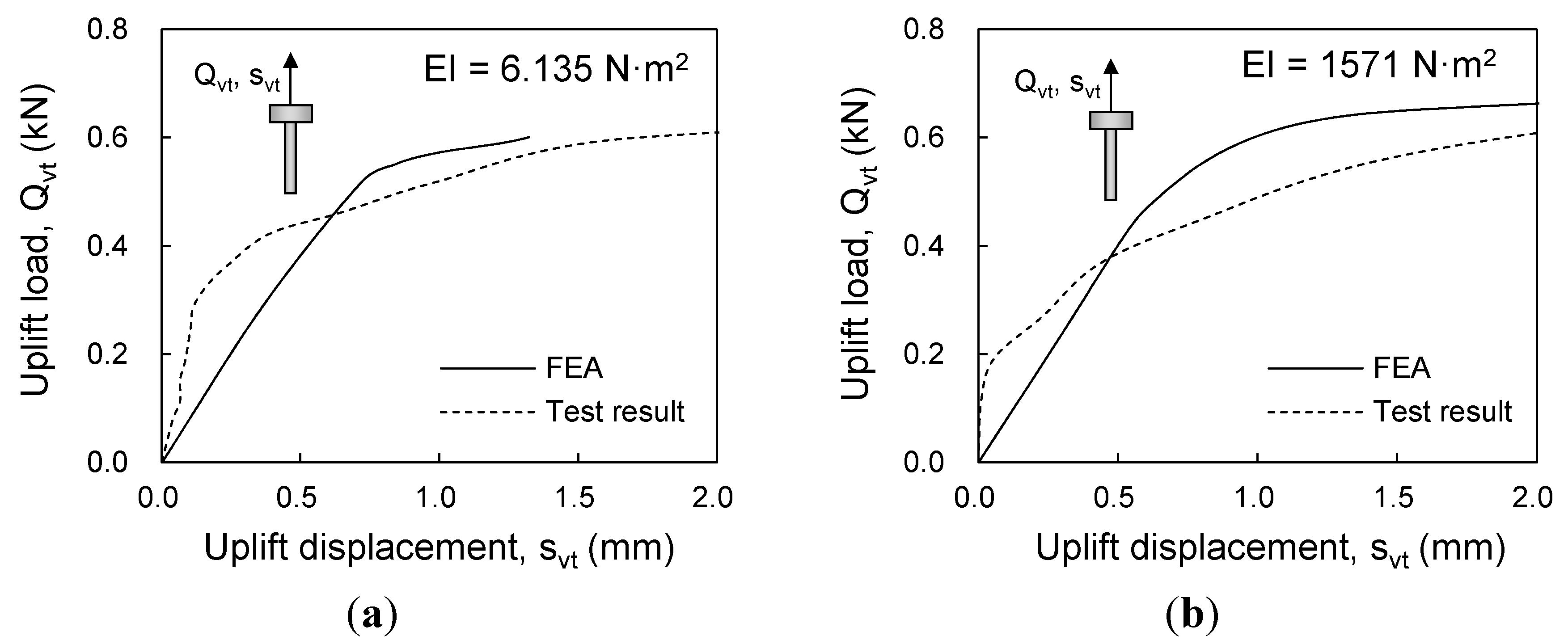
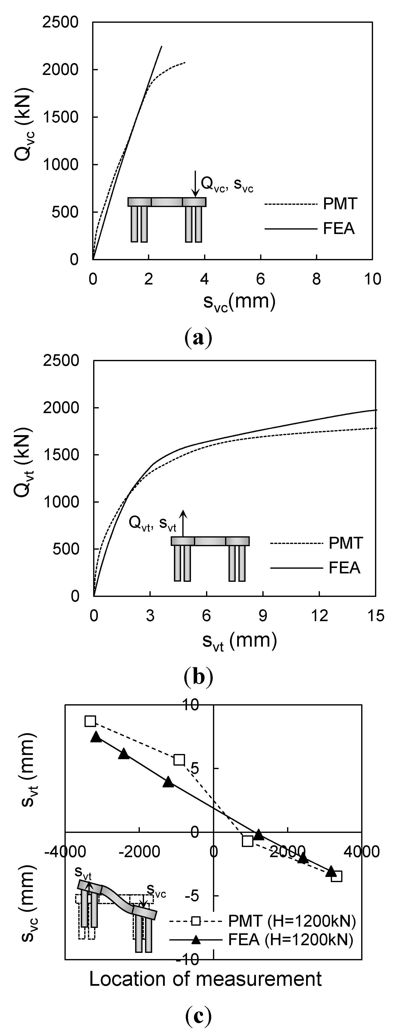
3.3. Comparison of Finite Element Analyses with Field Load Tests

To assess the validity of the finite element analysis, results from field load tests for the transmission tower structures were obtained and compared with those from the finite element analyses. Two field test cases were used, the small-scale model load tests reported in Kyung et al. [22] and larger-scale prototype model load tests conducted in the present study. For both cases, the transmission tower structures were prepared using connected foundations.
The small-scale model transmission structures consisted of an upper tower structure and lower foundations, as shown in Figure 6a. The foundation at each corner included a mat and piles that were embedded into the ground to a depth of 0.8 m. The width and height of the mat were 0.1 and 0.05 m and the diameter and length of the piles were 0.05 and 0.8 m, respectively. Two different types of connection beams were used in the tests: (1) low-stiffness beams with EI = 6.135 N·m2 and (2) high-stiffness beams with EI = 1571 N·m2.
Figure 6. Small-scale model load tests with connected foundations [22]: (a) model structures; (b) depth profiles of soil layer, SPT, and CPT results; and (c) FE model configuration.
Energies 08 04963 g006
The soils at the test site were clays classified into CL according to the unified soil classification system (USCS). The unit weight (γsat), specific gravity (Gs), water content (w), and plasticity index (PI) were 16.59 kN/m3, 2.69, 43.3%, and 23.3%, respectively. Unconfined compression and unconsolidated undrained (UU) triaxial tests were conducted, and su ranged from 8.4 to 11.1 kPa. Figure 6b shows the detailed soil profiles of the standard penetration (SPT) and cone penetration (CPT) test results. The detailed configuration of the finite element model for the small-scale model load tests is shown in Figure 6c. As the clay was quite homogeneous and pile length was only 0.8 m, a single layer was assumed in the finite element analysis with material properties given in Table 1. Mat and pile were assumed as linear-elastic materials with the elastic modulus (E) and Poisson’s ratio (υ) equal to 205 GPa and 0.3, respectively. The Mohr–Coulomb model was adopted with the undrained shear strength given in Table 1. Figure 7 shows the compared uplift load-displacement curves from the small-scale model tests and finite element analyses for two connection beam cases of EI = 6.135 and 1571 N·m2. As shown in Figure 7, reasonably close agreements are observed between measured and estimated results.
Table 1. Material properties for small-scale model load test.
MaterialModelDepth (m)γt1 (kN/m3)E2 (kN/m2)su3 (kN/m2)υ4
ClayMohr–Coulomb0–816.593,00011.080.5
MatLinear elastic-75205,000,000-0.3
PileLinear elastic-75205,000,000-0.3
γt1 = total unit weight, E2 = elastic modulus, su3 = undrained shear strength, υ4 = Poisson’s ratio.
Figure 7. Compared load-displacement curves of small-scale model tests and finite element analyses for connection beam cases of (a) EI = 6.135 N·m2 and (b) EI = 1571 N·m2.
Energies 08 04963 g007
The other field load test using a larger-scale prototype model was conducted in this study at Hwaseong, Korea. Figure 8a shows the configuration of the prototype model structure. The load height (zh) and contiguous length (w) of the transmission tower structures were 15 and 4.84 m, respectively. The mat foundations were made of concrete with width and height equal to 2.4 and 0.8 m, respectively. Four piles with a diameter of 0.318 m were used at the corners and were embedded to the depth of 17 m. The connection beams with 25% mat stiffness were used for this prototype structure. The width, height, and length of the connection beams were 0.6, 0.8, and 2.44 m, respectively.
Figure 8. The prototype model test for connected foundation: (a) detailed configuration of prototype model; (b) site investigation results for the site; and (c) FE model configuration.
Energies 08 04963 g008
Figure 8b shows the depth profiles of soil layers, SPT, and CPT results at the test site. It is seen that the top 4 m of soil was a slight OC clay layer, below which an NC clay layer extended down to the depth of 8 m. Mixed and weathered sand layers were observed to depths of 13 to 16 m, beneath which was a weathered rock layer. The pile base was placed on this weathered rock layer. The layered soil condition was considered for modeling the prototype model load test in the finite element analysis. Figure 8c shows the configuration of finite element model for the prototype model load test and Table 2 shows the material properties used in the analysis.
Table 2. Material properties for the prototype model load test.
MaterialModelDepth (m)γt1 (kN/m3)E2 (kN/m2)su3 (kN/m2)ϕ′4 (˚)υ5
OC ClayMohr–Coulomb0–418.729005–64-0.5
NC ClayMohr–Coulomb4–818.7290020-0.5
Mixed SandMohr–Coulomb8–1219.52,200–5,200-270.3
Weathered SandMohr–Coulomb12–1620.55,200–12,000-300.35
Weathered RockLE16–7025300,000--0.25
MatLE-2540,000,000--0.2
PileLE-75205,000,000--0.3
γt1 = total unit weight, E2 = elastic modulus, su3 = undrained shear strength, ϕ′4 = friction angle, υ5 = Poisson’s ratio.
Figure 9 compares the results from the prototype model load test (PMT) and finite element analysis (FEA). As shown in Figure 9a,b, the compressive and uplift load responses of the connected foundations from the finite element analyses were in close agreement with the measured results from the field load test. Figure 9c shows the estimated and measured vertical displacement profiles at lateral load of H = 1200 kN. The profiles of vertical and differential settlements also show reasonable agreement between FEM and PMT results.
Figure 9. Compared load-displacement curves of prototype model test (PMT) and finite element analysis (FEM): (a) compressive load responses; (b) uplift load responses; and (c) vertical settlement profiles.
Energies 08 04963 g009

4. Parametric Study Analysis

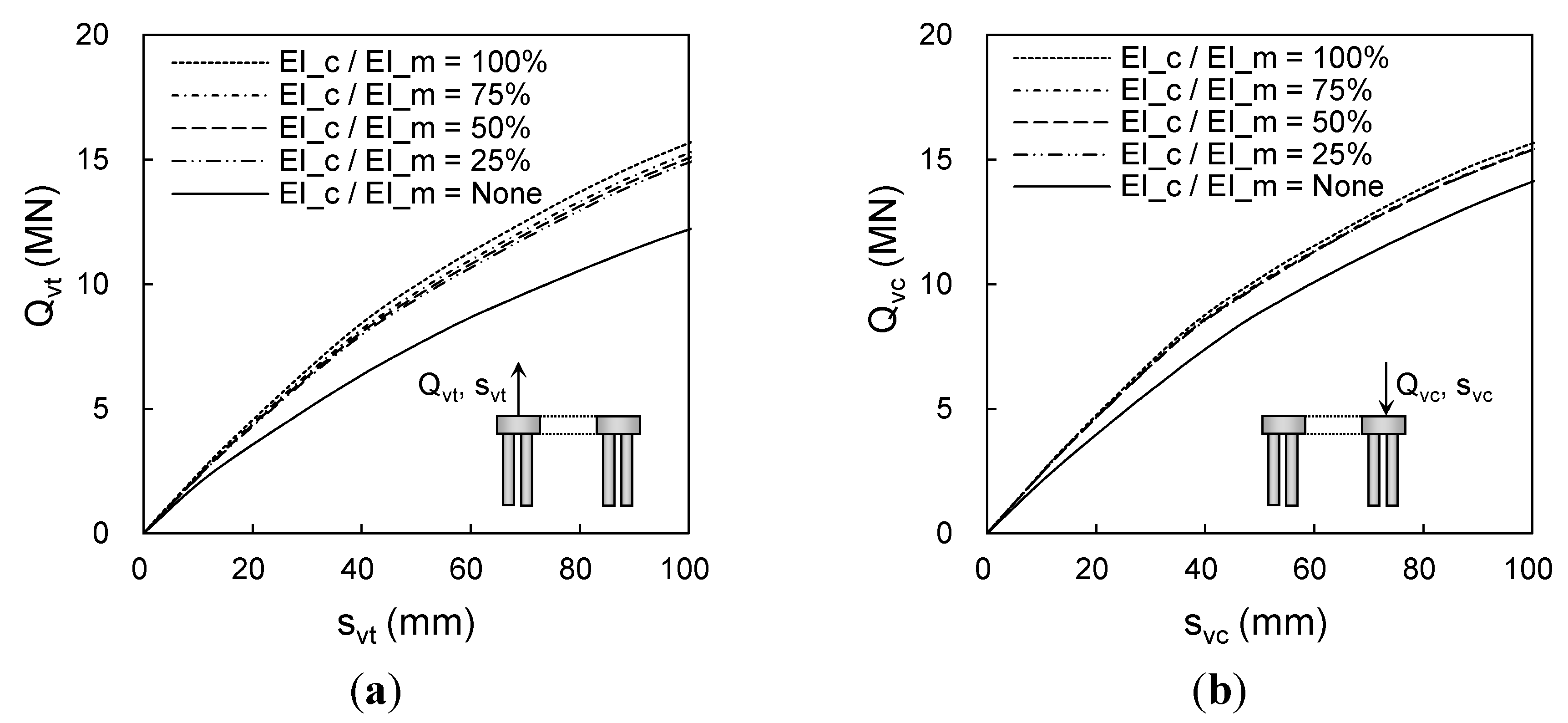
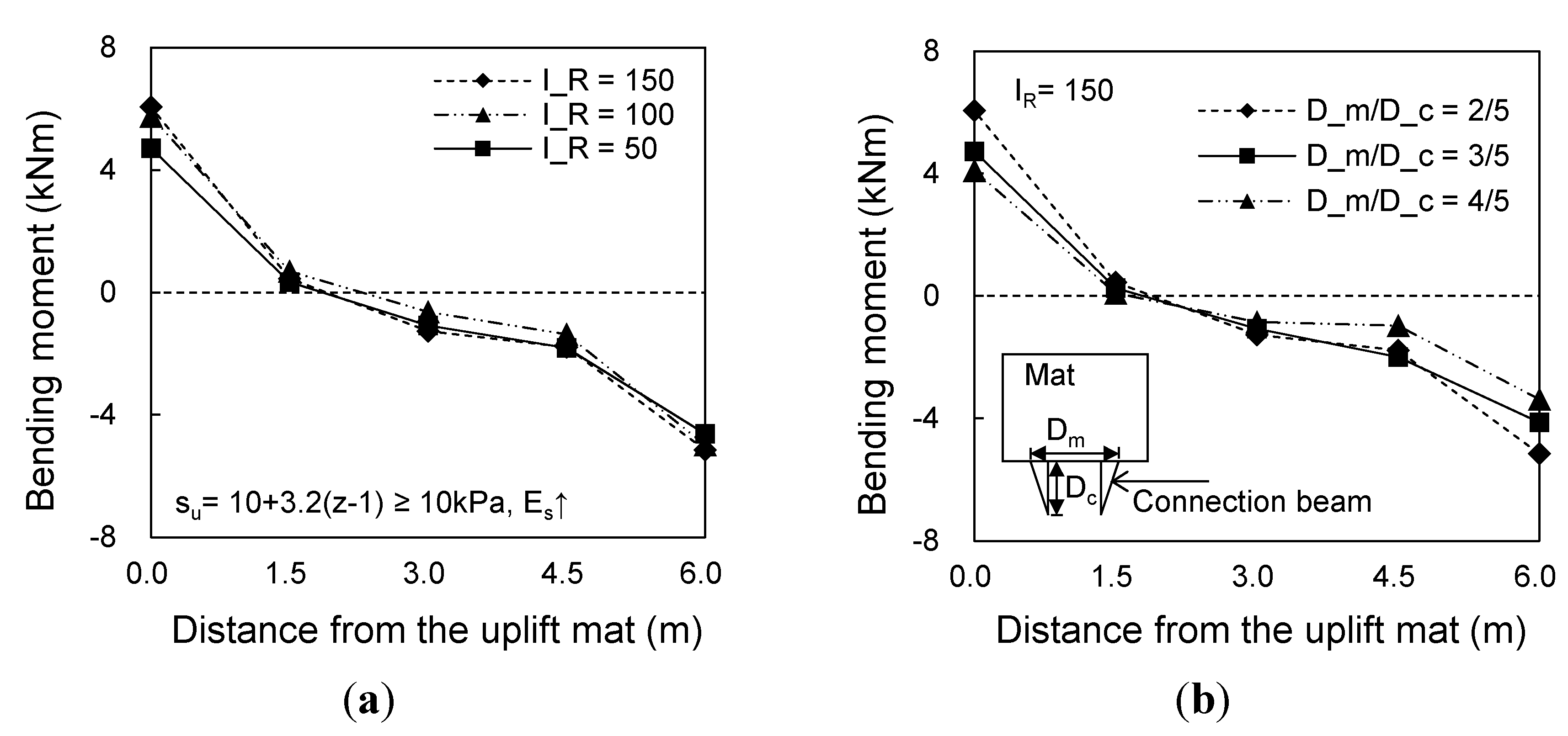
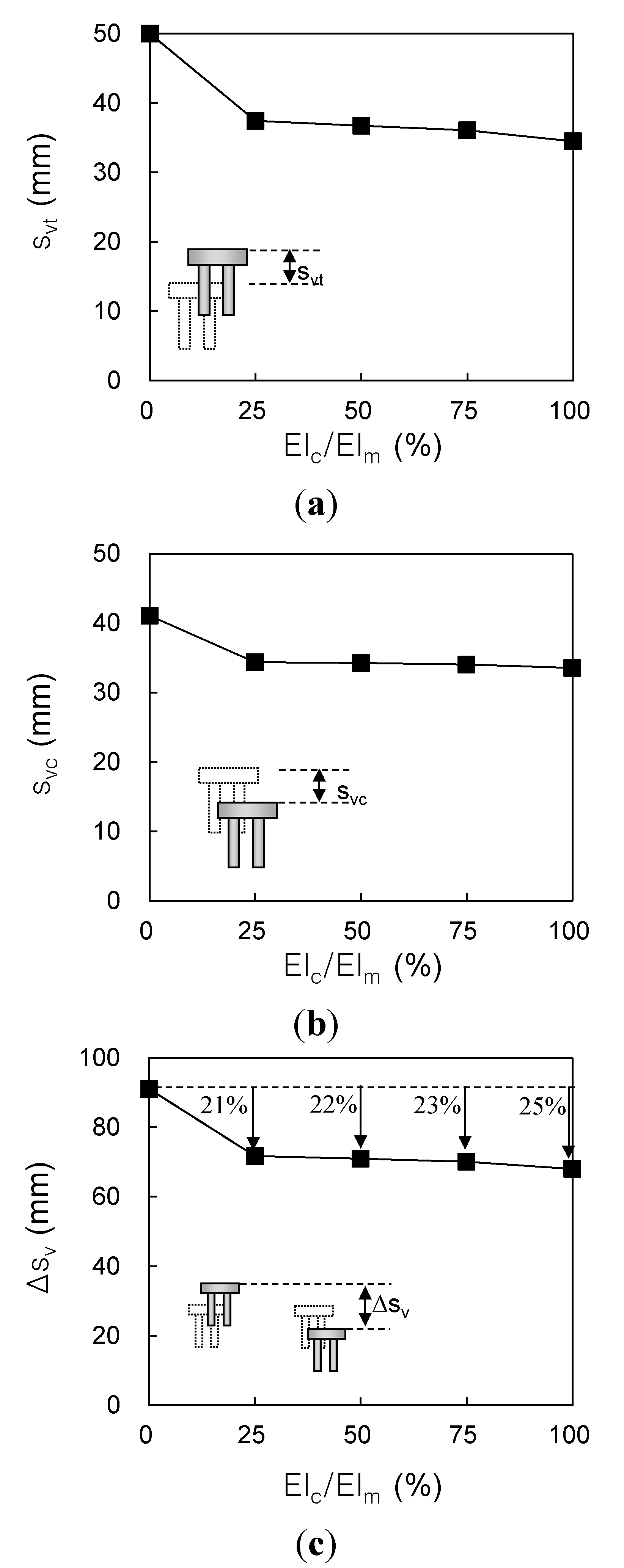
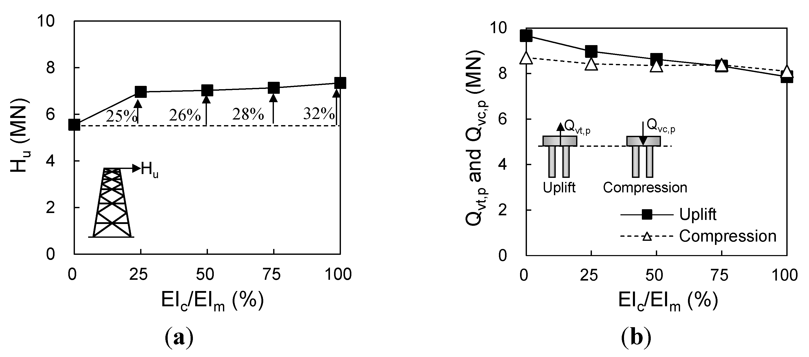
4.1. Effects of Connection Beam Stiffness

Figure 10 shows the load-displacement curves obtained from the finite element analyses for unconnected and connected foundations. The results for different ratios of connection-beam stiffness (EIc) to mat stiffness (EIm) were all included in Figure 10. In Figure 10a,b, the uplift and compressive load-displacement curves were plotted for clay with IR = 100. As shown in Figure 10, both the uplift and compressive load-carrying capacities increase as the connection beam stiffness increases. It is also noted that the amount of load-carrying capacity increase from the connected foundation was higher for the uplift foundation case than for the compressive foundation components. This is due to a higher confining effect on the uplift side where larger displacements and lower load carrying capacity are observed. When the uplift and compressive sides are connected, however, uplift and compressive displacements become similar due to the effect of the connection beam. This means that the use of connection beams would be more effective for the uplift foundations that usually control the design of transmission tower foundations.
Figure 10. Load-displacement curves with different connection beam of conditions: (a) uplift foundation and (b) compressive foundation components.
Energies 08 04963 g010
Figure 11 shows the reductions in vertical displacement with relative connection-beam stiffness (EIc/EIm). All displacements in Figure 11 were measured at a load equal to the ultimate load capacity of the unconnected foundation. Figure 11a,b shows those for the uplift displacement (svt) and compressive settlement (svc), respectively. The values of svt and svc both decreased with increasing connection beam stiffness. The reduction effect increased with increasing EIc/EIm but the reductions were relatively small after EIc/EIm equal to 25%. The reductions in uplift displacement (svt) in Figure 11a were larger than those of compressive settlement (svc) in Figure 11b. Reductions in differential settlements for unconnected and connected foundations are shown in Figure 11c. Note that the variation of differential settlement occurrence with EIc/EIm follows the same tendency to those of tensile and compressive displacements. Approximately 21–25% reductions were observed, showing similar tendency and efficiency to those shown in Figure 11a,b.
Figure 12 shows the lateral load capacity Hu of tower structure and uplift and compressive load capacities of connected foundation for different EIc/EIm. As shown in Figure 12a, increases in Hu show a similar tendency to those in Figure 11. Hu increased by 25%, 26%, 28%, and 32% for EIc/EIm values of 25%, 50%, 75%, and 100%, respectively.
Figure 12b shows the transferred uplift and compressive loads of Qvt,p and Qvc,p on the piles at the rear uplift and front compressive sides, respectively. Note that Qvc,p and Qvt,p do not include the mat capacity and thus Qvc,p is different Qvc. Both Qvc,p and Qvt,p decreased with increasing connection beam stiffness due to the load sharing effect of connection beams. For the unconnected foundation (EIc/EIm = 0), Qvt,p was larger than Qvc,p due to the contact resistance of the mat on the ground at compressive side. For the connected foundation, however, the stiffer the connection beam with increasing EIc/EIm, the smaller the difference between Qvc,p and Qvt,p. This is because connection beams confine the uplift and compressive foundations, together producing combined behavior.
Figure 11. Reductions in vertical displacements with connection beam: (a) uplift displacement (svt); (b) compressive settlement (svc); and (c) differential settlement (Δsv).
Energies 08 04963 g011
Figure 12. Load capacities of tower structure and connected foundation: (a) ultimate lateral load capacity of transmission tower (Hu) and (b) transferred uplift (Qvt,p) and compressive (Qvc,p) loads.
Energies 08 04963 g012

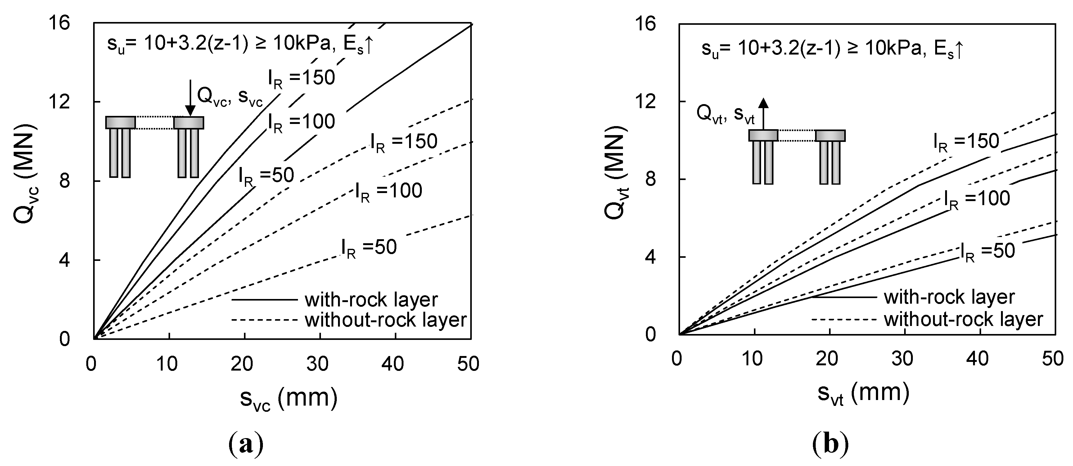
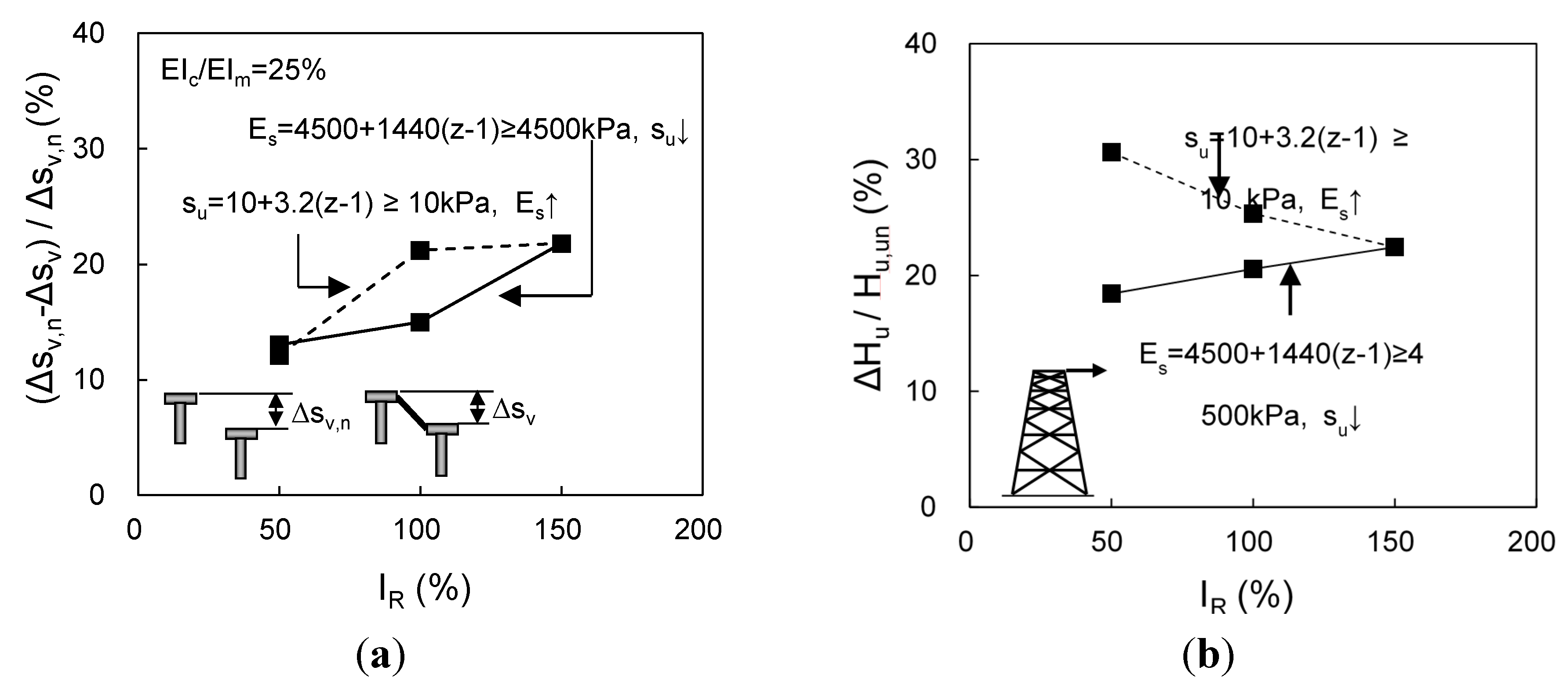
4.2. Effects of Soil Condition

To check the effect of soil condition on the performance of connected foundation, changes in differential settlement and Hu from connected foundations were obtained from the results of finite element analysis and plotted in Figure 13a,b with IR, respectively. As IR represents the combined characteristics of su and Es, for which values increase with soil depth (z), cases with different values of su and Es were considered and included in Figure 13. All results in Figure 13 were obtained for the 25% relative connection beam stiffness. As shown in Figure 13a, larger reductions in differential settlement are observed as IR increases for both increasing Es and decreasing su. For IR = 100, the higher Es case showed higher reduction. The results in Figure 13 indicate that reductions in differential settlement become larger as soil becomes stiffer with higher IR condition. This is because stiffer clays with higher IR produce less compressive settlement while changes in uplift displacements were smaller.
Figure 13. Effects of soil conditions on connected foundation: (a) reduction ratio of differential settlement and (b) increases in lateral load capacity of transmission tower.
Energies 08 04963 g013
Figure 13b shows the ratios of increase in lateral load capacity (ΔHu) for the transmission tower with connected foundation to Hu for unconnected case. It is seen that ΔHu/Hu decreases with increasing Es and increases with decreasing su. These results indicate that ΔHu/Hu increases more in weaker soil conditions with lower su than for higher Es cases. From the results in Figure 13a,b, it can be summarized that the use of a connected foundation is more effective in soft clays with lower su. For the effect of soil stiffness, however, different tendencies were observed for differential settlement and lateral load capacity.

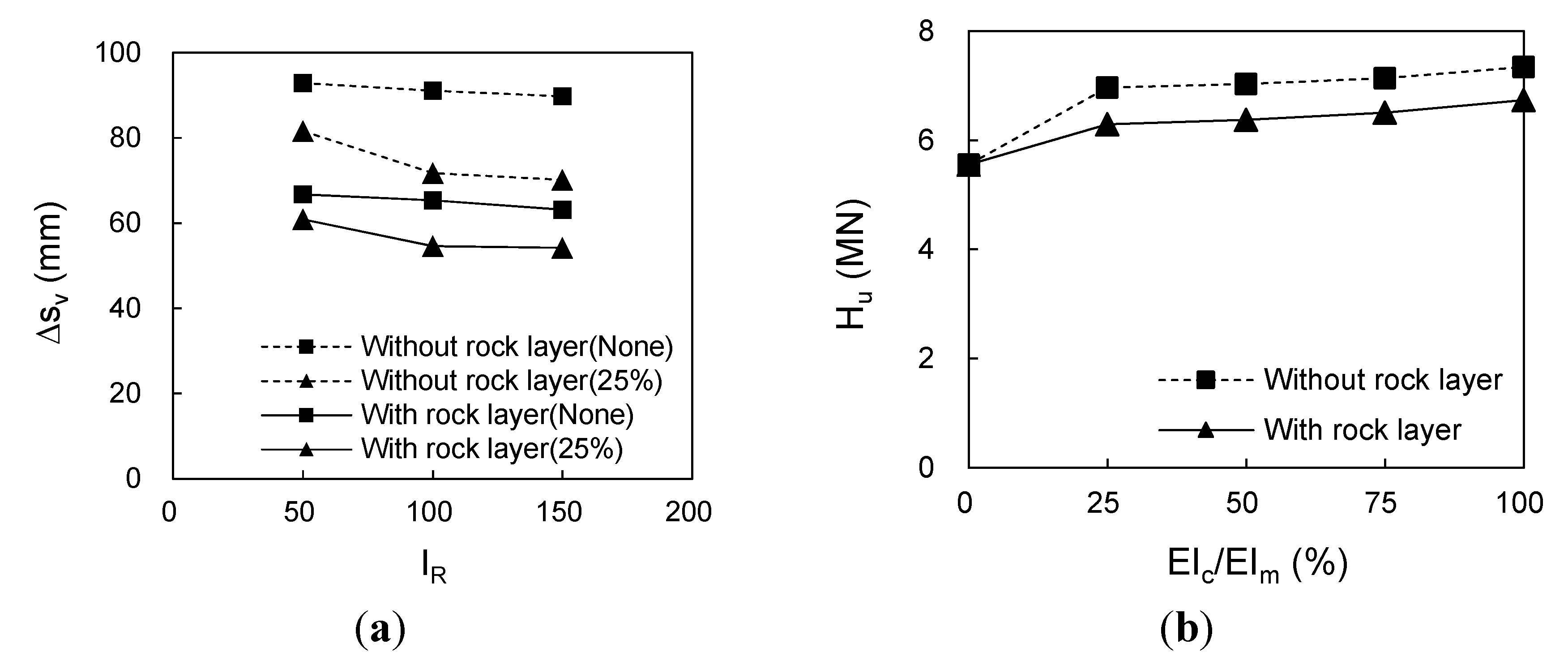
4.3. Effect of Bearing Rock Layer

Figure 14 shows the compressive and uplift load-displacement curves of connected foundations with and without a bearing rock layer. The compressive load-displacement curves for the with-rock layer condition are much higher than those for the without-rock layer condition. This can be attributed to increases in the end-bearing capacity of the piles that extend to the depth of the bearing rock layer. However, the uplift load-displacement curve demonstrates no major differences between with or without-rock layer conditions. This is because the existence of a rock layer does not contribute much to the uplift pile capacity that is mobilized on the pile shaft.
Figure 14. Load-displacement curves of connected foundations with and without bearing rock layer: (a) compressive and (b) uplift foundation.
Energies 08 04963 g014
Figure 15 shows the changes in differential settlement and lateral load capacity with and without a bearing rock layer. As shown in Figure 15a, smaller amounts of differential settlement were observed in all soil conditions for both unconnected and connected foundations when a bearing rock layer was present. This is due to restricted settlement of the pile base that is resting on the rock layer. It is also seen that reductions in differential settlement with the presence of connection beams were greater for the without-rock layer condition than for the with-rock layer condition.
Figure 15b shows that the lateral load capacity (Hu) of the transmission tower was higher in the absence of a rock layer than in the presence of a rock layer. When the foundation was not reinforced by connection beams, the values of Hu were similar for both with- and without-rock layer because each foundation behaves independently and the uplift capacity controls Hu anyway. When the foundation was reinforced by connection beams in a rock layer, the uplift displacement experienced a greater increase than the one that occurs in the absence of a rock layer because the overturning axis was closer to the compressive foundation, which was caused by decreasing compressive displacement. Therefore, the rate of Hu increase for connected foundations becomes lower when a bearing rock layer exists.
Figure 15. Differential settlement and lateral load capacity for different rock layer conditions: (a) differential settlement and (b) lateral load capacity of tower structure.
Energies 08 04963 g015

4.4. Bending Moment Distribution for Connection Beam

The connected foundation of the transmission tower is subjected to uplift and compressive loads on different sides, and bending moment occurs in the connection beam. The bending moment in the connection beam can cause structural damage, while this can be prevented or reduced by changing the shape of the beam. Figure 16a shows the distribution of bending moment along the connection beam in different soil conditions. As shown in Figure 16a, the bending moment was largest at ends and decreased with distance from the ends. It is seen that the distribution of bending moment is not symmetrical and shows the location of zero bending moment at the distance of 1/4 length from the uplift-side of the connection beam. Minor differences in the bending moment were observed for the results with different soil conditions.
In order to decrease the amount of bending moments of the connection beam, haunch-shaped connection beams were considered and analyzed in the finite element analysis. As shown in Figure 16b, the haunch shapes were defined by the ratio of Dm to Dc. The value of Dc was set equal to 0.61 m corresponding to 1/4 of connection beam length. The values of Dm were then changed to consider different haunch shapes. Three haunch-shaped connection beams were used in the finite element analysis. The considered Dm/Dc values were equal to 2/5, 3/5, and 4/5. Figure 16b shows the distribution of bending moments for the considered haunch shapes. The magnitude of bending moment of the connection beams decreased with increasing Dm/Dc showing 6.1, 4.7, and 4.1 kN·m for uplift side and 5.1, 4.1, and 3.4 kN·m for the compressive side with Dm/Dc equal to 2/5, 3/5, and 4/5, respectively. This confirms that introducing haunch-shaped connection beams is effective for increasing connection beam stability.
Figure 16. Distribution of bending moment along connection beams: (a) bending moment distribution for different soil conditions and (b) bending moment distributions for different haunch shapes.
Energies 08 04963 g016

5. Summary and Conclusions

In the present study, the effects of connected foundation on the performance of electrical transmission tower structures embedded in soft ground were investigated with consideration of various connection-beam and soil conditions. For this purpose, a series of finite element analyses were performed and used to analyze the improved performance of transmission tower foundation. To assess the validity of the finite element analysis, the field load test results were compared with those from the finite element analyses.
The application of connected foundation produced increases in resistance for uplift side higher than for compressive side. This indicates that the use of connection beams would be more effective for uplift foundations that usually control the design of transmission tower foundations. Uplift displacement and settlement both decreased with increasing connection beam, stiffness showing the most effective reduction ratio at EIc/EIm equal to 25%. The reductions in uplift displacement were larger than in compressive settlement. The lateral load capacity of a tower structure increased similarly to other resistance components.
For the effect of soil condition, it was seen that increases in the lateral load capacity Hu of a tower structure decreases with increasing Es and increases with decreasing su. This implies that the use of a connected foundation is more effective in soft clays with lower su. The compressive load carrying capacity for the with-rock layer condition was much higher than for the without-rock layer condition due to an increase in the end-bearing capacity of piles. Smaller amounts of differential settlement were observed in all soil conditions for both unconnected and connected foundations when a bearing rock layer was present. When the foundation was not reinforced by connection beams, the values of Hu were similar for both with- and without-rock layers. It was confirmed that introducing haunch-shaped connection beams is effective for increasing connection beam stability.
The results obtained from this study indicate that the connected foundation is an effective option to improve the resilience of electrical transmission tower infrastructures with the effect of increasing load carrying capacity and reducing differential settlements. It is particularly effective within soft grounds where extra safety margins are necessary as there is increasing possibility of damage with weaker soil conditions. In addition, extreme weather events due to climate change can cause harmful changes in subsoil condition with chances of additional settlements and unexpected reduction in the bearing capacity of foundations. The design strategy for optimizing connected foundations of a transmission tower system given in this study can be used to prepare more robust and sustainable transmission infrastructures with improved resilience against various climate change scenarios and unfavorable soil conditions.

Acknowledgments

This work was supported by a Power Generation & Electricity Delivery of the Korea Institute of Energy Technology Evaluation and Planning (KETEP) grant funded by the Korean Ministry of Knowledge Economy (No. 20101020200060). This work was also supported by the Basic Science Research Program through the National Research Foundation of Korea (NRF) grant funded by the Korean government (MSIP) (Nos. 2011-0030040 and 2013R1A1A2058863).

Author Contributions

All three authors significantly contributed to the scientific study and writing. Doohyun Kyung and Junhwan Lee contribute to the overall idea, planning, financing, analyzing, and writing of the manuscript; Youngho Choi performed finite element analyses of connected foundations.

Conflicts of Interest

The authors declare no conflict of interest.

References

  1. Ebinger, J.; Walter, V. Climate Impacts on Energy Systems: Key Issues for Energy Sector Adaptation; World Bank: Washington, DC, USA, 2011. [Google Scholar]
  2. Yates, D.; Luna, B.Q.; Rasmussen, R.; Bratcher, D.; Garre, L.; Chen, F.; Tewari, M.; Hansen, P.F. Assessing climate change hazards to electric power infrastructure: A sandy case study. IEEE Power Energy Mag. 2014, 12, 66–75. [Google Scholar] [CrossRef]
  3. Wilbanks, T.; Fernandez, S.; Backus, G.; Garcia, P.; Jonietz, K.; Kirshen, P.; Savonis, M.; Solecki, B.; Toole, L.; Allen, M.; et al. Climate Change and Infrastructure, Urban Systems, and Vulnerabilities; Technical report for the U.S. Department of Energy in Support of the National Climate Assessment, U.S. Department of Energy: Oak Ridge, TN, USA, 2012.
  4. European Commission. Commission Staff Working Document: Adapting Infrastructure to Climate Change. In An EU Strategy on Adaptation to Climate Change; European Commission: Brussels, Belgium, 2013. [Google Scholar]
  5. HM Government. Climate Resilient Infrastructure: Preparing for a Changing Climate. UK for The Stationery Office Limited on behalf of the Controller of Her Majesty’s Stationery Office: London, UK, May 2011. [Google Scholar]
  6. Neumann, J.E.; Price, J.C. Adapting to Climate Change: The Public Policy Response−Public Infrastructure; An Initiative of the Climate Policy Program at RFF, Resources for the Future: Washington, DC, USA, June 2009. [Google Scholar]
  7. Konrad, J.; Samson, M. Hydraulic conductivity of kaolinite-silt mixtures subjected to close-system freeze and thaw consolidation. Can. Geotech. J. 2000, 37, 857–869. [Google Scholar] [CrossRef]
  8. Othman, M.A.; Besnson, C.H. Effect of Freeze-Thaw on the Hydraulic Conductivity of Three Compacted Clays from Wisconsin; Transportation Research Board: Washington, DC, USA, 1992; pp. 118–125. [Google Scholar]
  9. Yarbasi, N.; Kalkan, E.; Akbulut, S. Modification of the geotechnical properties, as influenced by freeze-thaw, of granular soils with waste additives. Cold Reg. Sci. Technol. 2007, 48, 44–55. [Google Scholar] [CrossRef]
  10. Ausilio, E.; Conte, E. Influence of groundwater on the bearing capacity of shallow foundations. Can. Geotech. J. 2005, 42, 663–672. [Google Scholar] [CrossRef]
  11. Shahriar, M.A.; Sivakugan, N.; Das, B.M.; Urquhart, B.; Tapiolas, M. Water table correction factors for settlement of shallow foundations in granular soils. Int. J. Geomech. ASCE 2015, 15, 06014015. [Google Scholar] [CrossRef]
  12. Yasuhara, K.; Murakami, S.; Mimura, N.; Komine, H.; Recio, J. Influence of global warming on coastal infrastructural instability. Sustain. Sci. 2007, 2, 13–25. [Google Scholar] [CrossRef]
  13. IEEE. IEEE Guide for Transmission Structure Foundation Design and Testing, IEEE Standard 691–2001. In Proceedings of the IEEE Power Engineering Society and the American Society of Civil Engineers, New York, NY, USA, 2001.
  14. Jang, S.H.; Kim, H.K.; Ham, B.W.; Chung, K.S. A study on the transmission tower foundation design and construction method-A focus of cylindrical foundation. J. Korean Inst. Electr. Eng. (KIEE) 2007, 56, 1031–1034. [Google Scholar]
  15. KECA. Handbook for Transmission Structure; Korea Electrical Contractors Association: Seoul, Korea, 2003. [Google Scholar]
  16. Morinaga, Y.; Kamiji, M.; Imoto, S.; Ogawa, S.; Iwamori, K. Transmission Tower Foundation in Japan. In Proceedings of the Transmission and Distribution Conference and Exhibition, Yokohama, Japan, 6–10 October 2002; Volume 3, pp. 2162–6165.
  17. Kim, J.B.; Cho, S.B. The design and the full load test results of 765 kV tower foundation. In Proceeding of the Korean Institute of Electrical Engineers (KIEE) Fall National Conference, Seoul, Korea, November 1995; pp. 447–449.
  18. Jeoung, S.S.; Ham, H.K.; Lee, D.S. Load transfer analysis of drilled shaft reinforced by soil nails. J. Korean Geotech. Soc. 2004, 20, 37–47. [Google Scholar]
  19. Nam, D.S.; Kim, S.I.; Lee, J.H.; Yoon, K.S. Optimization of Reinforcement Effect of Large-diameter drilled deep foundation. J. Korean Geotech. Soc. 2003, 19, 207–216. [Google Scholar]
  20. Yuan, G.L.; Li, S.M.; Xu, G.A.; Si, W.; Zhang, Y.F.; Shu, Q.J. The anti-deformation performance of composite foundation of transmission tower in mining subsidence area. Prodedia Earth Planet. Sci. 2009, 1, 571–576. [Google Scholar] [CrossRef]
  21. TEPCO. Design Guideline for UHV Foundation; Tokyo Electric Power Company: Tokyo, Japan, 1988. [Google Scholar]
  22. Kyung, D.H.; Kim, D.H.; Lee, J.H. Improved mechanical performance of connected foundations for transmission tower structures in soft soils. Eng. Struct. 2014. in submit. [Google Scholar]
  23. KEPCO. Design Standard for Transmission Tower Foundation; DS-1110; Korea Electronic Power Corporation: Seoul, Korea, December 2011. [Google Scholar]
  24. Yang, J.S.; Yang, Y.H.; Yan, L.; Zhang, H.L.; Hu, X.; Tang, P. Construction scheme choice of large-span tunnels under-passing high voltage transmission tower and its application. Chin. J. Rock Mech. Eng. 2012, 31, 1184–1191. [Google Scholar]
  25. Wang, S.; Yang, J.; Yang, Y.; Zhang, F. Construction of large-span twin tunnels below a high-rise transmission tower: A case study. Geotech. Geol. Eng. 2014, 32, 453–467. [Google Scholar] [CrossRef]
  26. PLAXIS 3D. Foundation PLAXIS 3D Foundation User Manual, Version 2.0; Brinkgreve, R.B., Swolfs, W.M., Eds.; PLAXIS Inc.: Delft, The Netherlands, 2008. [Google Scholar]
  27. Liang, F.Y.; Chen, L.Z.; Shi, X.G. Numerical analysis of composite piled raft with cushion subjected to vertical load. Comput. Geotech. 2003, 30, 443–453. [Google Scholar] [CrossRef]
  28. Hansbo, S. Foundation Engineering; Elsevier Science B.V.: Amsterdam, The Netherlands, 1994; pp. 89–91. [Google Scholar]
  29. Jamiolkowski, M.; Ladd, C.C.; Germaine, J.T.; Lancellotta, R. New developments in field and laboratory testing of soils, theme lecture. In Proceedings of the 11th International Conference on Soil Mechanics and Found Engineering, San Francisco, CA, USA, 1985; Volume 1, pp. 57–153.
  30. Mersi, G. Reevaluation of su(mob)=0.22σ’p using laboratory shear tests. Can. Geotech. J. 1989, 26, 162–164. [Google Scholar]
  31. Skempton, A.W. Discussion on the planning and design of new Hong Kong airport. Proc. Inst. Civ. Eng. 1957, 7, 305–307. [Google Scholar]
  32. Wroth, C.P. Interpretation of in-situ soil tests. Geotechnique 1984, 34, 449–489. [Google Scholar] [CrossRef]
  33. Coduto, D.P. Foundation Design—Principles and Practices; Prentice Hall: Englewood Cliffs, NJ, USA, 1994. [Google Scholar]
  34. Terzaghi, K.; Peck, R.B. Soil Mechanics in Engineering Practice; John Wiley & Sons: New York, NY, USA, 1967. [Google Scholar]

