Abstract
The rational power sharing among different interface converters should be determined by the converter capacity. In order to guarantee that each converter operates at the ideal condition, considering the radial and mesh configuration, a modified strategy for load power sharing accuracy enhancement in droop-controlled DC microgrid is proposed in this paper. Two compensating terms which include averaging output power control and averaging DC voltage control of neighboring converters are employed. Since only the information of the neighboring converter is used, the complexity of the communication network can be reduced. The rational distribution of load power for different line resistance conditions is realized by using modified droop control that can be regarded as a distributed approach. Low bandwidth communication is used for exchanging sampled information between different converters. The feasibility and effectiveness of the proposed method for different network configurations and line resistances under different communication delay is analyzed in detail. Simulation results derived from a DC microgrid with three converters is implemented in MATLAB/Simulink to verify the proposed approach. Experimental results from a 3 × 10 kW prototype also show the performance of the proposed modified droop control scheme.
1. Introduction
Nowadays, development and utilization of green energy has become an important concern [1,2]. In order to achieve coordinated energy management of different types of green energy, the microgrid is presented which is currently attracting increasing attention [3]. Most microgrids adopt AC distribution the same as in conventional power systems. However, some renewable energy sources have DC output, such as the photovoltaic (PV) system, the fuel cell, and energy storages. Therefore, the DC-type microgrid can be more beneficial in efficiency enhancement and power quality improvement.
Since the power is delivered to load from different sources through the transmission lines, the power transmission efficiency and the rationality power sharing accuracy of distribution are particularly important [4,5]. At the same time, power electronic converters are indispensable in distributed generation (DG) due to the requirement of renewable energy regulations. In order to avoid circulating currents among the converters without using any dedicated communication between them [6], and to reduce the line loss and improve the overall efficiency of the DC power system [7,8,9], an improved droop control method was proposed in [10]. This method can be used simultaneously to compensate the voltage drop and enhance the load distribution accuracy. However, it also has the drawback of heavy communication traffic since sampled data from all the converters are needed. Meanwhile, only radial configuration is taken into account.
To overcome these drawbacks, a modified droop control method is proposed in this paper. The average voltage and average output power of the adjacent converters are selected as the control variables. Since only the data of the adjacent converters are used, the communication traffic is not so high. The information of voltage and power for each converter is transferred through a low bandwidth communication network. The influence of line impedance and power sharing accuracy are discussed in this method. At the same time, the stability of the method could be improved because the control system does not require a centralized controller. Both mesh and radial system architectures are studied. Simulation and experimental results demonstrate the feasibility of the proposed method with case studies based on both system configurations. The outline of the paper is as follows. In Section 2 the drawbacks of traditional droop control are discussed. This is followed by analysis of droop control issues in Section 3. Improved droop control is discussed in Section 4. Finally, the simulation results are compared with the experimental results in Section 5.
2. Traditional Droop Control
2.1. State-of-the-Art of DC Microgrids
In recent years, with the increasing penetration of distributed sources with DC output such as photovoltaic (PV), battery storage, and the fuel cell, DC microgrids have been intensively studied. Their advantages are shown in the following aspects, including the technical considerations of control, economical operation and efficiency:
- Control [11,12]: DC microgrids have simpler models and control since there is no phase angle, frequency or reactive power, while synchronization, reactive power flow and harmonics have to be considered for AC systems which leads to more complicated control system. Moreover, DC is chosen over AC because it facilitates integrating most modern electronic loads, energy storage devices, and DG technologies—all of them inherently DC.
- Economical operation [13,14,15]: Economical operation in DC microgrids can be achieved without complex and computation-intensive optimization algorithms and as pointed out in the existing literature, the total cost of ownership, infrastructure, equipment, maintenance and operation are lower in DC microgrids.
- Efficiency [16,17,18]: The system efficiency becomes higher due to the reduction of conversion losses of inverters between DC output sources and loads. DC microgrids already have a fault-ride-through capability of their own due to the stored energy of the DC capacitor and the voltage control of the AC/DC converter.
2.2. Configuration of DC Microgrids
In DC microgrids, due to the distributed characteristics of renewable energy sources, the interface converters are connected parallel to each other [19]. The configuration of DG is generally divided into two groups, namely mesh configuration and radial configuration [20,21,22], as shown in Figure 1. By using Thevenin equivalent circuits, the simplified models of a DC microgrid are shown in Figure 2. Traditional droop control [23,24] is widely used in the DC microgrids, which can be expressed as
where
is the reference value of the DC output voltage of each converter, and
is the actual output voltage of each converter.
is the output power of each converter, m0 is the droop coefficient, and i = 1, 2, 3···.
Meanwhile, the reference of the DC output voltage is selected as 380 V [25,26,27], since this level is globally accepted for standardized components with the best balance of economics and safety. Power distribution at 380 V has some inherent advantages as follows:
- Equipment costs become lower.
- Distribution capabilities are enhanced.
- Sustainability is improved due to reduced copper use.
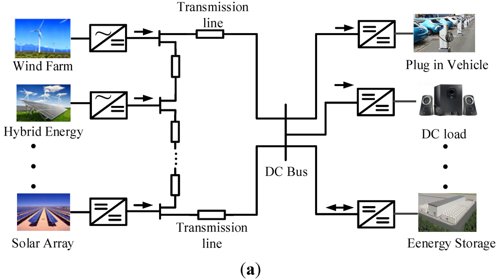
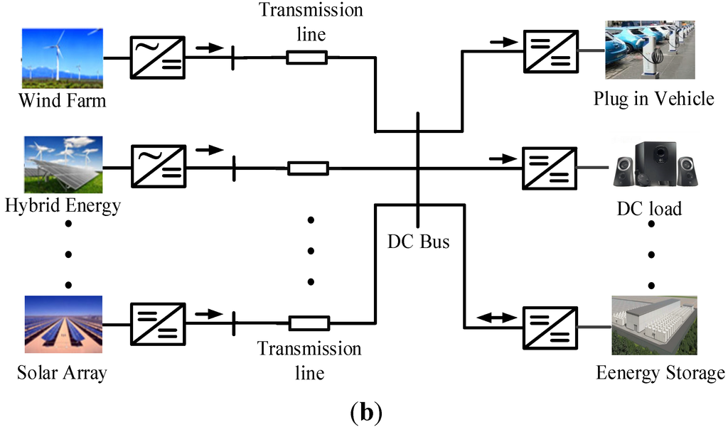
Figure 1.
Distributed generation (DG) sources parallel operation diagrams. (a) Mesh configuration. (b) Radial configuration.
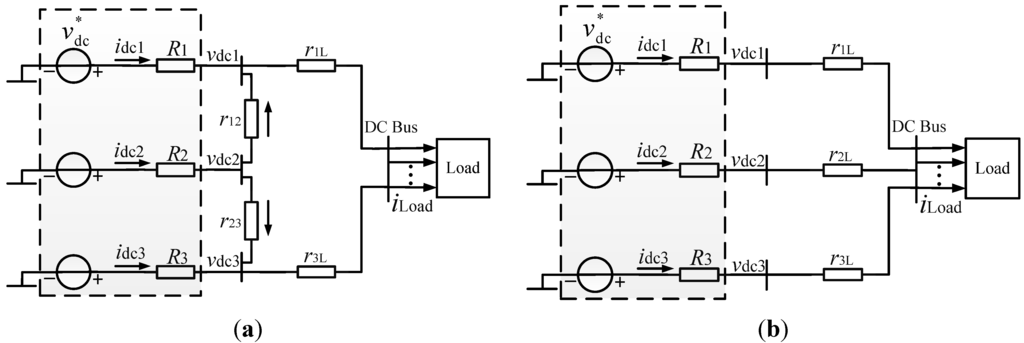
Figure 2.
Simplified model of DC microgrid. (a) Mesh configuration (b) Radial configuration.
2.3. Drawbacks of Traditional Droop Control
The diagram of traditional droop control is depicted in Figure 3. According to Figure 3 and Equation (1), the principle of droop control is shown as follows: The value of the actual DC output voltage linearly decreases with increasing DC output power for each converter.
Figure 3.
Droop control diagram at the DC side.
Some drawbacks in traditional droop control in DC microgrids are as follows [28,29,30]:
- Deviation of bus voltage is inevitable.
- There is trade-off between power-sharing accuracy and voltage deviation.
In general, if the scale of DC microgrids is small, the line impedance can be ignored. The bus voltages are approximately equal and load power distribution can be properly achieved. However, if the scale of DC microgrids increases, the impact of line impedance should be considered. In this case, sharing the accuracy of load power should be enhanced.
3. Analysis of Droop Control Issues
The aforementioned drawbacks of the traditional droop control method in both mesh and radial configurations are analyzed in detail as follows.
3.1. Mesh Configuration
By using the listed voltage and current equations based on the multiple nodes of the simplified system models, the converter output current for mesh and radial configuration in DC microgrids can be derived. According to Kirchhoff's law, the following circuit equations can be derived as in Figure 2a:
where vdci is DC side output voltage of converter # i (i = 1, 2, 3), idci is DC side output current, vL is load voltage, iL is load side current, RL is load side resistance, rij (i = 1, 2, 3, j = 2, 3) is line resistance between different converters; Ri is the virtual resistance.
Based on above circuit analysis and combining Equations (2) and (3), DC side output current can be obtained:
where
In DC microgrids, by using traditional droop control method, accurate load power sharing accuracy can be obtained when the converter DC output power is set to be inversely proportional to the corresponding droop coefficient, the following expression can be obtained:
Based on the above analysis, it can be seen that the power sharing error can be eliminated if and only if the droop coefficient and line impedance satisfy the relationship in Equation (5). However, this assumption is only suitable for an ideal system and the practical system is not satisfied. This is the limitation of the traditional droop control method in the mesh configuration of DC microgrids.
3.2. Radial Configuration
From the simplified model of a multi-bus radial configuration in Figure 2b, the load voltage and current equations can be obtained:
Based on Equation (6) the relationship of idci and
is shown as
The DC side output current can be expressed as:
where
By combining Equations (5) and (8), the expected power sharing accuracy can be obtained. According to the aforementioned theoretical derivation and analysis, it was shown that droop control can induce the inevitable load power sharing error when considering the value of line impedance, and irrational power sharing can thereby cause voltage degradation. The serious imbalance between each line resistance may lead to the condition that the output power of some converters exceeds the maximum power rating, and consequently causes the failure of the converter.
4. Proposed Approach
In order to solve the two problems of induced traditional droop control, this paper proposes a method of controlling the average values of the DC-link voltage of adjacent converters as well as the output power to compensate the voltage deviation induced by droop control, and simultaneously improve the load power sharing accuracy. The whole control diagram of the system is given in Figure 4. Compared to the existing method of averaging the voltage and power based on global information, the improved control method alleviates the communication traffic and further reduces the dependence on the communication system. The DC-link voltage references of the two adjacent converters are as follows:
where
is output DC-link voltage reference of the ith converter,
is line DC-link voltage reference,
and
are the output voltages of the ith converter’s two adjacent converters,
is the ith converter’s output power,
and
are the output power of the ith converter’s two adjacent converters, ki is the proportional sharing accuracy of output power, m0 is the coefficient of traditional droop control, GLPF is low pass filter introduced in droop control, ωs is the cut-off frequency of the filter, Gpiv and Gpip are two compensating terms of improved droop control: The averaging voltage controller and averaging power controller, are both traditional PI controllers. The communication delay of the transfer variable is Gd, which can be expressed as the following:
In the control system, low bandwidth communication is employed to transfer the sampling data of the DC-link voltage and power values between different converter units. Voltage deviations induced by droop control can be eliminated by PI controllers I for the average values of DC-link voltage and power respectively. However, there is a variety of renewable energy distributed into microgrids by multiple converters, which are separate and have no need of high frequency telecommunication lines. Hence, the sampling for all the transmission voltage and power between the converters will cause unnecessary errors and increase communication complexity. In this paper, there is improved droop control method sampling of the average value of the DC-link voltages and power between the adjacent converters to eliminate voltage deviations or power sharing error which are induced by droop control. Meanwhile, load power can be proportionally shared by the power compensating controller II. Finally the goal of accurate proportional sharing of the DC output power is achieved without a centralized controller.
In the mesh configuration, the communication delay is a very sensitive parameter for system stability which is shown in Figure 5a. If the communication delay is set to a large value, poles III, IV and VI move towards the imaginary axis, and the system becomes unstable.
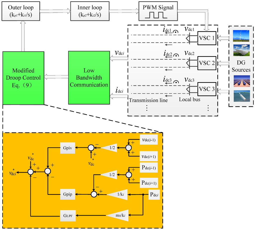
Figure 4.
Detailed diagram of the proposed droop control system.
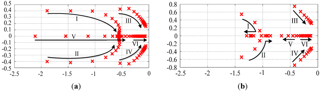
Figure 5.
Closed-loop dominant poles for varying communication delay. (a) Mesh configuration (b) Radial configuration.
Figure 5b gives the location of the dominant closed-loop poles in the radial configuration while varying the communication delays from 1 to 10 s. Poles I, II, and V keep to the left side of the s plane, which means they do not harm the system stability. However, poles III, IV and VI move towards an imaginary axis which leads to an unstable status when increasing communication delay or encountering communication loss.
5. Simulations and Experimental Results
Simulations based on MATLAB/Simulink were performed to evaluate the performance of the proposed method of improved droop control, and the feasibility of the control method was verified by considering different line resistance rij, and communication delay τ, based on two kinds of configurations. The parameters for the DC microgrids system are listed in Table 1. The differences between the maximum and the minimum value of the DC side power of different converters as well as the DC side voltage are defined respectively as follows:
where i = 1, 2, 3 denotes the converter’s sequence number, j = 1, 2, 3, 4 denotes the type of specific case.
εj = max (Pdci) – min (Pdci)
εj ≤ 0.1 × Pdci
δj = max (vdci) – min (vdci)
δj ≤ 0.05 × vdci

Table 1.
DC microgrids system parameters.
| Item | Symbol | Value | ||||||||
|---|---|---|---|---|---|---|---|---|---|---|
| Reference of DC output voltage | vdc | 380 V | ||||||||
| Load resistance | RL | 19 Ω | ||||||||
| Power sharing proportion (Converter #i=1,2,3) | ki | 1 | ||||||||
| LPF cutting frequency | fc | 20 Hz | ||||||||
| Communication delay | τ | 0.1 s or 1 s | ||||||||
| Droop coefficient | m0 | 0.0015 | ||||||||
| Averaging voltage controller proportion coefficient | kpv | 2 × 10⁻³ | ||||||||
| Averaging voltage controller integral coefficient | kiv | 4.5 × 10⁻² | ||||||||
| Averaging power controller proportion coefficient | kpp | 2.3 × 10⁻³ | ||||||||
| Averaging power controller integral coefficient | kip | 5.5 × 10³ | ||||||||
| Mesh configuration | Radial configuration | |||||||||
| Case No. | r1L | r12 | r23 | r3L | τ | Case No. | r1L | r2L | r3L | τ |
| 1 | 0.8 Ω | 1.0 Ω | 1.0 Ω | 1.2 Ω | 0.1 s | 4 | 0.8 Ω | 1.0 Ω | 1.2 Ω | 0.1 s |
| 2 | 0.8 Ω | 1.0 Ω | 1.0 Ω | 1.2 Ω | 1 s | 5 | 0.8 Ω | 1.0 Ω | 1.2 Ω | 1 s |
| 3 | 0.6 Ω | 1.2 Ω | 1.2 Ω | 1.8 Ω | 1 s | 6 | 0.6 Ω | 1.2 Ω | 1.8 Ω | 1 s |
5.1. Simulation Results for Mesh Configuration
First, the same line resistance and different communication delay are used to test the performance of the proposed control system in Case 1 and Case 2. The responses for power sharing accuracy and voltage restoration enhancement are shown in Figure 6a–d. Before t = 1 s the compensating controllers are not activated. The traditional droop control sharing error ε is 2530 W among different converters. The DC output average voltage is increased 4.4 V. When t > 1 s, the compensating controllers are activated to eliminate the error of output power sharing and restore the DC voltage. At the same time, the communication delays of 0.1 s and 1 s are tested, respectively. The DC-side output power of each converter gradually becomes equal, and the DC-side voltage deviation δ of each converter is less than 5% of the voltage rating.
Second, the same communication delay and different transmission line resistance are used in Case 3. When the proportion of the line resistance increases, the power sharing error is changed from 2530 W to 4176 W compared to the results in Case 1 and Case 2. The DC output voltage deviation is increased from 11–15 V. The changes for DC output power and DC voltage are shown in Figure 6e,f.
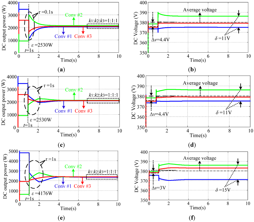
Figure 6.
Transient responses for mesh configuration in the DC microgrid. (a) Case 1, Power sharing accuracy; (b) Case 1, Voltage restoration; (c) Case 2, Power sharing accuracy; (d) Case 2, Voltage restoration; (e) Case 3, Power sharing accuracy; (f) Case 3, Voltage restoration.
5.2. Simulation Results for Radial Configuration
In Case 4 and Case 5, the transient response for radial configuration is shown in Figure 7a–d. It should be noted that the simulation conditions in these two cases are the same as in Case 1 and Case 2. The maximum power error ε is 793 W among the different converters. The maximum deviation of DC-side voltage among each converter is 5.4 V which is less than 5% of the rated value. In Case 6, the same communication delay and different transmission line resistance are also used. With the proportion of the line resistance increasing, the power sharing error is increased from 793 W to 2156 W. The DC output voltage deviation is increased from 5.4 V to 15.6 V. The changes for output power and DC voltage are shown in Figure 7e,f.
In this paper, we chose the mesh configuration and the middle of the converter is not connected to load directly, the start of DC power is determined by some factors in the system e.g., the DC output voltage of two adjacent converters and transmission line resistance etc. It is more complicated than radial configuration. By using the modified droop control method, the expected results can be implemented.
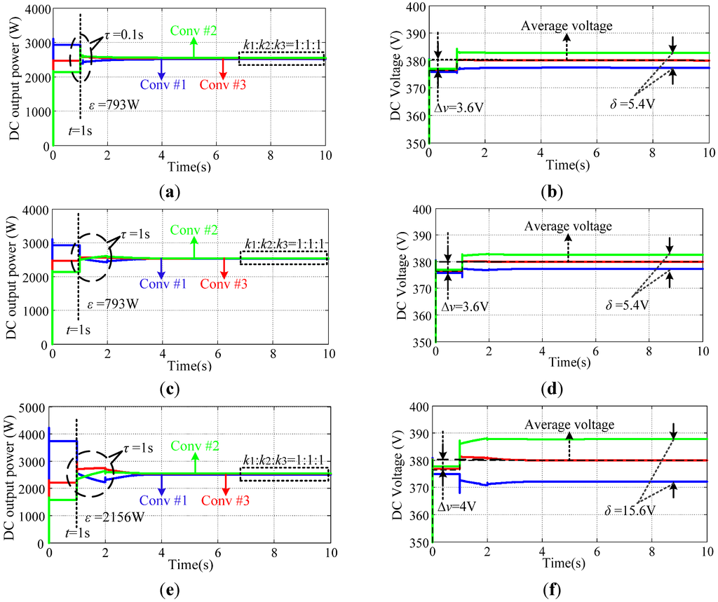
Figure 7.
Transient responses for radial configuration in the DC microgrid. (a) Case 4, Power sharing accuracy; (b) Case 4, Voltage restoration; (c) Case 5, Power sharing accuracy; (d) Case 5, Voltage restoration; (e) Case 6, Power sharing accuracy; (f) Case 6, Voltage restoration.
5.3. Experimental Verification
A prototype with 3 × 10 kW was used to verify the theoretical results from the previous section. The system parameters are the same as in Table 1. The performance of the modified control system can be verified by the test results of the DC output power and voltage.
The experimental results for Case 3 in the mesh configuration are shown in Figure 8a,b. The modified control was started when t = 0.5 s. Before t = 0.5 s, compensating terms are not activated. Hence, the power sharing error can be found. The differences between the maximum and minimum DC output power among converters is 4149 W. After activating the modified droop control method, the power and voltage waveforms are modified. During this period, the output power gradually becomes equal which satisfies the objective of sharing the proportion (ki = 1), and the system is also stable when the communication delay τ = 1 s. The average value of the DC output voltage is increased by 3.1 V and the maximum error of the DC output voltage is kept at 16.2 V which is lower than 5% of the reference voltage.
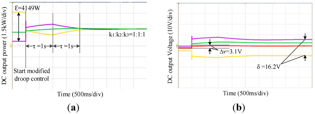
Figure 8.
Modified control method test result for Case 3 in the mesh configuration. (a) Power sharing accuracy; (b) Voltage restoration.
The experimental results for Case 6 in the radial configuration are shown in Figure 9a,b. The power sharing error is smaller than the mesh configuration before t = 0.5 s. The differences between the maximum and minimum DC power among converters is 2137 W. When the compensating items are activated at 2 s, the output power gradually becomes equal. The average value of the DC output voltage is increased by 3 V by using the modified control method. The corresponding maximum output voltage error is 16 V which is also lower than 5% of the reference voltage.
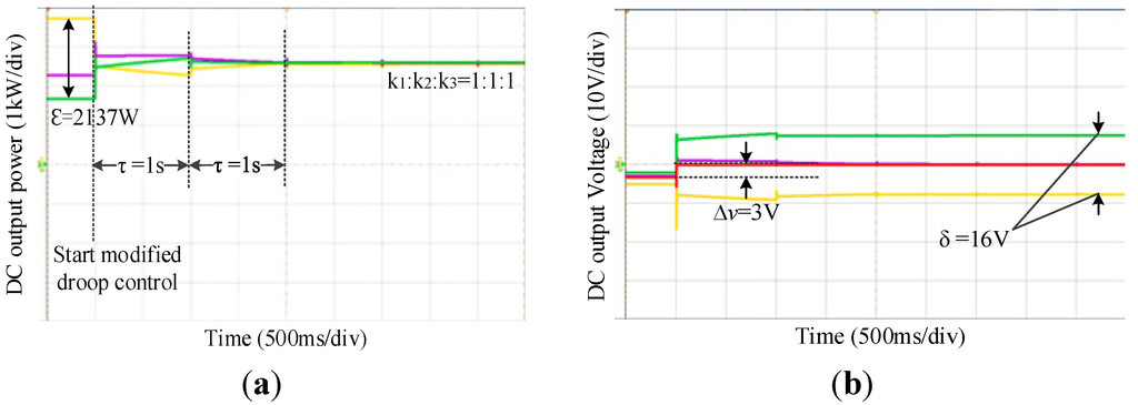
Figure 9.
Modified control method test result for Case 6 in radial configuration. (a) Power sharing accuracy; (b) Voltage restoration.
6. Conclusions
In order to improve the overall performance of a droop-controlled DC microgrid, a modified distributed control method for mesh and radial configuration was proposed and studied. The key points included in this paper are summarized as follows:
- (1)
- It was demonstrated that the feasibility and stability of the control system can be guaranteed with both mesh and radial configurations.
- (2)
- Local DC output voltage deviation can be eliminated and the load power sharing accuracy can be enhanced with the modified droop control method.
- (3)
- The proposed control method only relies on the data of voltage and current sampled from two adjacent converters, which reduces the stress on the communication system.
- (4)
- The control system is also stable considering the longer communication delay time and larger mismatch of line resistance.
Author Contributions
All authors contributed to this work by collaboration. Yiqi Liu was the main author of this manuscript. Jianze Wang, Ningning Li, Yu Fu, and Yanchao Ji provided some useful suggestions in the construction of the paper. All authors revised and approved the publication.
Conflicts of Interest
The authors declare no conflict of interest.
References
- Dasgupta, S.; Mohan, S.N.; Sahoo, S.K.; Panda, S.K. Application of four-switch-based three-phase grid-connected inverter to connect renewable energy source to a generalized unbalanced microgrid system. IEEE Trans. Ind. Electron. 2013, 60, 1204–1215. [Google Scholar] [CrossRef]
- Hakimi, S.M.; Moghaddas-Tafreshi, S.M. Optimal planning of a smart microgrid including demand response and intermittent renewable energy resources. IEEE Trans. Smart Grid 2014, 5, 2889–2900. [Google Scholar] [CrossRef]
- Eghtedarpour, N.; Farjah, E. Distributed charge/discharge control of energy storages in a renewable-energy-based DC micro-grid. IET Renew. Power Gener. 2014, 8, 45–57. [Google Scholar] [CrossRef]
- Vandoorn, T.L.; de Kooning, J.D.M.; Meersman, B.; Guerrero, J.M.; Vandevelde, L. Automatic power-sharing modification of P/V droop controllers in low-voltage resistive microgrids. IEEE Trans. Power Deliv. 2012, 27, 2318–2325. [Google Scholar] [CrossRef]
- Augustine, S.; Mishra, M.; Lakshminarasamma, N. Adaptive droop control strategy for load sharing and circulating current minimization in low-voltage standalone DC microgrid. IEEE Trans. Sustain. Energy 2015, 6, 132–141. [Google Scholar] [CrossRef]
- Guerrero, J.M.; Vasquez, J.C.; Matas, J.; de Vicuña, L.G.; Castilla, M. Hierarchical control of droop-controlled AC and DC microgrids—A general approach toward standardization. IEEE Trans. Ind. Electron. 2011, 58, 158–172. [Google Scholar] [CrossRef]
- Rouzbehi, K.; Miranian, A.; Candela, J.I.; Luna, A.; Rodriguez, P. A generalized voltage droop strategy for control of multiterminal DC grids. IEEE Trans. Ind. Appl. 2015, 51, 607–618. [Google Scholar] [CrossRef]
- Bevrani, H.; Shokoohi, S. An intelligent droop control for simultaneous voltage and frequency regulation in islanded microgrids. IEEE Trans. Smart Grid 2013, 4, 1505–1513. [Google Scholar] [CrossRef]
- Dou, X.; Quan, X.; Wu, Z. Improved control strategy for microgrid ultracapacitor energy storage systems. Energies 2014, 7, 8095–8115. [Google Scholar] [CrossRef]
- Lu, X.; Guerrero, J.M.; Sun, K.; Vasquez, J.C. An improved droop control method for DC microgrids based on low bandwidth communication with DC bus voltage restoration and enhanced current sharing accuracy. IEEE Trans. Power Electron. 2014, 29, 1800–1812. [Google Scholar] [CrossRef]
- Maknouninejad, A.; Qu, Z.; Lewis, F.L.; Davoudi, A. Optimal, nonlinear, and distributed designs of droop controls for dc microgrids. IEEE Trans. Smart Grid 2014, 5, 2508–2516. [Google Scholar] [CrossRef]
- Wang, B.; Sechilariu, M.; Locment, F. Intelligent DC microgrid with smart grid communications: Control strategy consideration and design. IEEE Trans. Smart Grid 2012, 3, 2148–2156. [Google Scholar] [CrossRef]
- Liang, C.; Shahidehpour, M. DC Microgrids: Economic operation and enhancement of resilience by hierarchical control. IEEE Trans. Smart Grid 2014, 5, 2517–2526. [Google Scholar] [CrossRef]
- Kanchev, H.; Colas, F.; Lazarov, V.; Francois, B. Emission reduction and economical optimization of an urban microgrid operation including dispatched pv-based active generators. IEEE Trans. Sustain. Energy 2014, 5, 1397–1405. [Google Scholar] [CrossRef]
- Nutkani, I.U.; Wang, P.; Poh, C.L.; Blaabjerg, F. Autonomous economic operation of grid connected DC microgrid. In Proceedings of the 2014 IEEE 5th International Symposium on Power Electronics for Distributed Generation Systems (PEDG), Galway, Ireland, 24–27 June 2014; pp. 1–5.
- Kwasinski, A. Quantitative evaluation of DC microgrids availability: Effects of system architecture and converter topology design choices. IEEE Trans. Power Electron. 2011, 26, 835–851. [Google Scholar] [CrossRef]
- Yukita, K.; Shimizu, Y.; Goto, Y.; Yoda, M.; Ueda, A.; Ichiyanagi, K.; Hirose, K.; Takeda, T.; Ota, T.; Okui, Y.; et al. Study of AC/DC power supply system with DGs using parallel processing method. In Proceedings of the International Power Electronics Conference (IPEC)-ECCE, Sapporo, Japan, 21–24 June 2010; pp. 722–725.
- Kakigano, H.; Miura, Y.; Ise, T. Low-voltage bipolar-type DC microgrid for super high quality distribution. IEEE Trans. Power Electron 2010, 25, 3066–3075. [Google Scholar] [CrossRef]
- Shadmand, M.B.; Balog, R.S. Multi-objective optimization and design of photovoltaic-wind hybrid system for community smart DC microgrid. IEEE Trans. Smart Grid 2014, 5, 2635–2643. [Google Scholar] [CrossRef]
- Mehrizi-Sani, A.; Iravani, R. Potential-function based control of a microgrid in islanded and grid-connected modes. IEEE Trans. Power Syst. 2010, 25, 1883–1891. [Google Scholar] [CrossRef]
- Prasai, A.; Du, Y.; Paquette, A.; Buck, E.; Harley, R.G.; Divan, D. Protection of meshed microgrids with communication overlay. In Proceedings of the 2010 IEEE Energy Conversion Congress and Exposition (ECCE), Atlanta, GA, USA, 12–16 September 2010; pp. 64–71.
- Shukla, S.; Deng, Y.; Shukla, S.; Mili, L. Construction of a microgrid communication network. In Proceedings of the 2014 IEEE PES Innovative Smart Grid Technologies Conference (ISGT), Washington, DC, USA, 19–22 February 2014; pp. 1–5.
- Luo, F.; Lai, Y.M.; Loo, K.H.; Tse, C.K.; Ruan, X. A generalized droop-control scheme for decentralized control of inverter-interfaced microgrids. In Proceedings of the 2013 IEEE International Symposium on Circuits and Systems (ISCAS), Beijing, China, 19–23 May 2013; pp. 1320–1323.
- Wang, W.; Zeng, X.; Tang, X.; Tang, C. Analysis of microgrid inverter droop controller with virtual output impedance under non-linear load condition. IET Power Electron. 2014, 7, 1547–1556. [Google Scholar] [CrossRef]
- Becker, D.J.; Sonnenberg, B.J. DC microgrids in buildings and data centers. In Proceedings of the 2011 IEEE 33rd International Telecommunications Energy Conference (INTELEC), Amsterdam, The Netherlands, 9–13 October 2011; pp. 1–7.
- Emerge Alliance. Available online: http://www.emergealliance.org/Standards/DataTelecom/Overview.aspx (accessed on 20 March 2015).
- Wu, T.-F.; Chang, C.-H.; Lin, L.-C.; Yu, G.-R.; Chang, Y.-R. DC-bus voltage control with a three-phase bidirectional inverter for DC distribution systems. IEEE Trans. Power Electron. 2013, 28, 1890–1899. [Google Scholar] [CrossRef]
- Olivares, D.E.; Mehrizi-Sani, A.; Etemadi, A.H.; Canizares, C.A.; Iravani, R.; Kazerani, M.; Hajimiragha, A.H.; Gomis-Bellmunt, O.; Saeedifard, M.; Palma-Behnke, R.; et al. Trends in microgrid control. IEEE Trans. Smart Grid 2014, 5, 1905–1919. [Google Scholar] [CrossRef]
- Choi, J.; Jeong, H.Y.; Choi, J.-Y. Voltage control scheme with distributed generation and grid connected converter in a DC microgrid. Energies 2014, 7, 6477–6491. [Google Scholar] [CrossRef]
- Kim, J.; Guerrero, J.M.; Rodriguez, P.; Teodorescu, R.; Nam, K. Mode adaptive droop control with virtual output impedances for an inverter-based flexible AC microgrid. IEEE Trans. Power Electron. 2011, 26, 689–701. [Google Scholar] [CrossRef]
© 2015 by the authors; licensee MDPI, Basel, Switzerland. This article is an open access article distributed under the terms and conditions of the Creative Commons Attribution license (http://creativecommons.org/licenses/by/4.0/).