Multi-Objective Structural Optimization Design of Horizontal-Axis Wind Turbine Blades Using the Non-Dominated Sorting Genetic Algorithm II and Finite Element Method
Abstract
: A multi-objective optimization method for the structural design of horizontal-axis wind turbine (HAWT) blades is presented. The main goal is to minimize the weight and cost of the blade which uses glass fiber reinforced plastic (GFRP) coupled with carbon fiber reinforced plastic (CFRP) materials. The number and the location of layers in the spar cap, the width of the spar cap and the position of the shear webs are employed as the design variables, while the strain limit, blade/tower clearance limit and vibration limit are taken into account as the constraint conditions. The optimization of the design of a commercial 1.5 MW HAWT blade is carried out by combining FEM analysis and a multi-objective evolutionary algorithm under ultimate (extreme) flap-wise load and edge-wise load conditions. The best solutions are described and the comparison of the obtained results with the original design is performed to prove the efficiency and applicability of the method.1. Introduction
The blade is one of the most important components of wind turbines. A successful structural design of Horizontal-Axis Wind Turbine (HAWT) blades must satisfy a wide range of objectives, such as minimization of weight and cost, resistance to extreme and fatigue loads, restricted tip deflections, and avoiding resonances, but some of these objectives are in conflict [1]. Thus, optimization is a complex procedure characterized by several trade-off decisions aimed at finding the optimum overall combination of performance and economy. The decision-making process is very difficult and the design trends are not uniquely established. A number of different commercial wind turbine blades have been optimized by experimental tests and simplified analytical methods, but there is no clear evidence on which of these has to be regarded as optimal.
In general, the weight and cost of the turbine are the keys to making wind energy competitive with other sources of power [2]. Most modern wind turbine blades are made of glass fiber reinforced polymer (GFRP) due to its light weight, high strength and stiffness, superior fatigue and corrosion properties. However, as the size of the blades becomes larger, the blade weight grows rapidly (approximately as a cubic power of length) and GFRP cannot satisfy the structural requirements, which leads to the use of lighter and stronger materials such as carbon fiber reinforced polymer (CFRP) [3]. The usage of CFRP can efficiently decrease the blade weight, which has a multiplier effect throughout the system including the foundation, but since CFRP is almost 10 times more expensive than GFRP, the obvious disadvantage is increased material costs. The combination of GFRP and CFRP in an appropriate way to achieve optimal utilization (reducing both the weight and the material cost) is an important issue worthy of research. Thus, the weight and the material cost of the blade are set to be a multi-objective function in this study.
A number of papers have recently described how to deal with the structural design problems of blades using numerical models and optimization techniques. Liao [4] developed a multi-criteria constrained optimum design model to minimize the blade mass. The thickness and the location of layers on spar caps were selected as the design variables and an improved particle swarm optimization algorithm was used to search for the optimum solution. Similarly, the authors in [5,6] used the First-Order optimization method and a particle swarm optimization (PSO) algorithm combined with the finite element method (FEM) to minimize the mass of a 1.5 MW wind turbine blade, respectively. Hu [7] presented an automated optimization process, wherein the layer thickness, material type and orientation angle of GFRP/CFRP layers are optimized to reduce the total cost and mass of a HAWT composite blade based on ultimate limit state analysis. Jureczko [8] selected the shell thickness, the web thickness, the number and the arrangement of stiffening ribs as design variables. The design process of the blades is formulated as a multi-objective optimization task to minimize the blade vibrations, minimize the material cost and maximize the output generated, etc. However, only the mass of the blade is given in the final results. The results of other objectives and the parameters of the blade structure are not discussed in detail.
In these papers, optimization methods are described where a single objective function is taken into account at each time with the presence of constraints. The problem involving multiple objectives is addressed using a single objective function where the multiple objectives are combined by means of appropriate weights. Thus, these methods do not have the capability to obtain the real set of trade-off solutions among multiple objectives. In many circumstances, however, the designer is interested in knowing the complete set of optimal blade configurations which correspond to the desired objectives.
This paper considers a two-objective optimization strategy of minimizing the weight as well as the material cost of a 1.5 MW HAWT blade. The main characteristics of the blade structure, namely, the number and the location of layers in the spar cap, the position of the shear webs and the width of the spar cap are employed as design variables. The optimization design for the blade is carried out under the action of ultimate flap-wise load, edge-wise load and their combination conditions using a non-dominated sorting genetic algorithm (NSGA) II and a FEM model of the blade for structural analysis.
2. Properties of the Blade
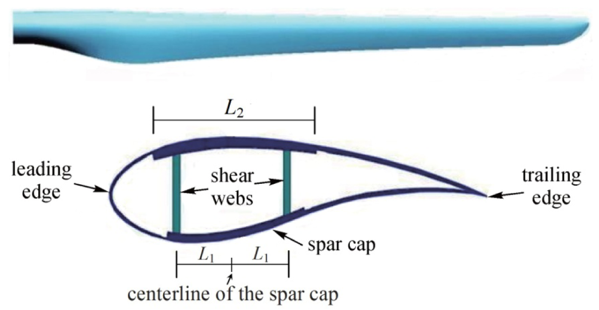
The original blade, with a length of 37 m and a weight of 6580.4 kg, is composed of three parts: root, skin and shear webs. Figure 1 shows the geometry and a typical structural cross section of the blade. The materials consist of a surface gel coat, reinforcing materials and unidirectional glass fiber for the skin and the spar cap. Balsa and PVC core materials are also used in the leading edge, the trailing edge, and the shear webs. Material properties of GFRP and CFRP are listed in Table 1.
The finite element method (FEM) has traditionally been used in the development of wind turbine blades mainly to investigate the structural performance in terms of global stress/strain levels, tip deflections and frequencies [9–12]. The FEM model of the proposed blade is created by using the well-known commercial software package ANSYS. Since its establishment and validation have been introduced in details in our previous work [6], only a brief overview will be provided here.
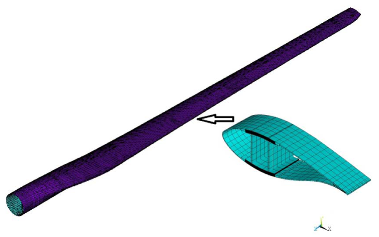
The FEM model of the blade is a parametric model, which means that the main structural parameters of the blade can be modified to create various blade models. The SHELL91 and the SHELL99 types are used for modeling the thick sandwich structures and the other parts of the blade, respectively. In order to simplify the model, the shear webs and the spar cap are connected directly without considering the effect of the adhesives. A regular quadrilateral mesh generation method is used to generate elements with low aspect ratios to prevent producing erroneous results. In this work, a few changes in the spar cap of the model are made for a better parameterization, and the blade weight of the modified FEM model is 6555.2 kg. The FEM model of the blade is shown in Figure 2.
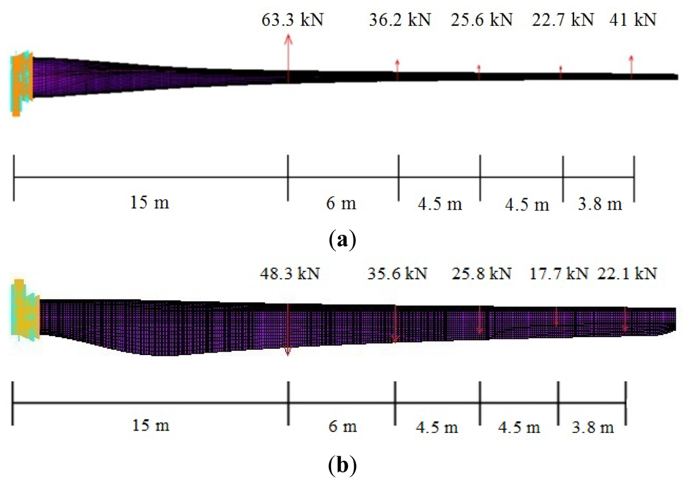
The loading on a wind turbine blade is stochastic and has components from the following sources: aerodynamic, gravitational, inertial (centrifugal and gyroscopic) and operational (gridfailure, braking, etc.). Design loads for a blade include the ultimate flap-wise load, edge-wise load and their combination in the form of a moment distribution along the blade length [13,14]. All the three load cases are considered to investigate the structural performance of the blade. The ultimate flap-wise load and edge-wise load distributions of the FEM model are shown in Figure 3.
3. Formulation of the Optimization Problem
3.1. Design Variables
The spar cap of the blade consists of laminates made by primarily unidirectional fibers to carry the flap-wise and edge-wise bending loads. Its thickness is typically large in comparison to those of the shear webs and the outer shells [15]. Consequently, the spar cap makes a major contribution to the overall weight and cost of a HAWT blade. The shear webs are designed to resist shear force within the cross-section of the foil when the blade is under the bending loads, their positions will have an influence on the structural performance (the strength and stiffness) of the blade. The overall weight and the cost of the blade can further decrease if the shear webs are repositioned appropriately. Hence, the spar cap parameters (the number and the location of layers in the spar cap, the width of the spar cap) and the shear webs parameters (the positions of the shear webs) are used as the design variables.
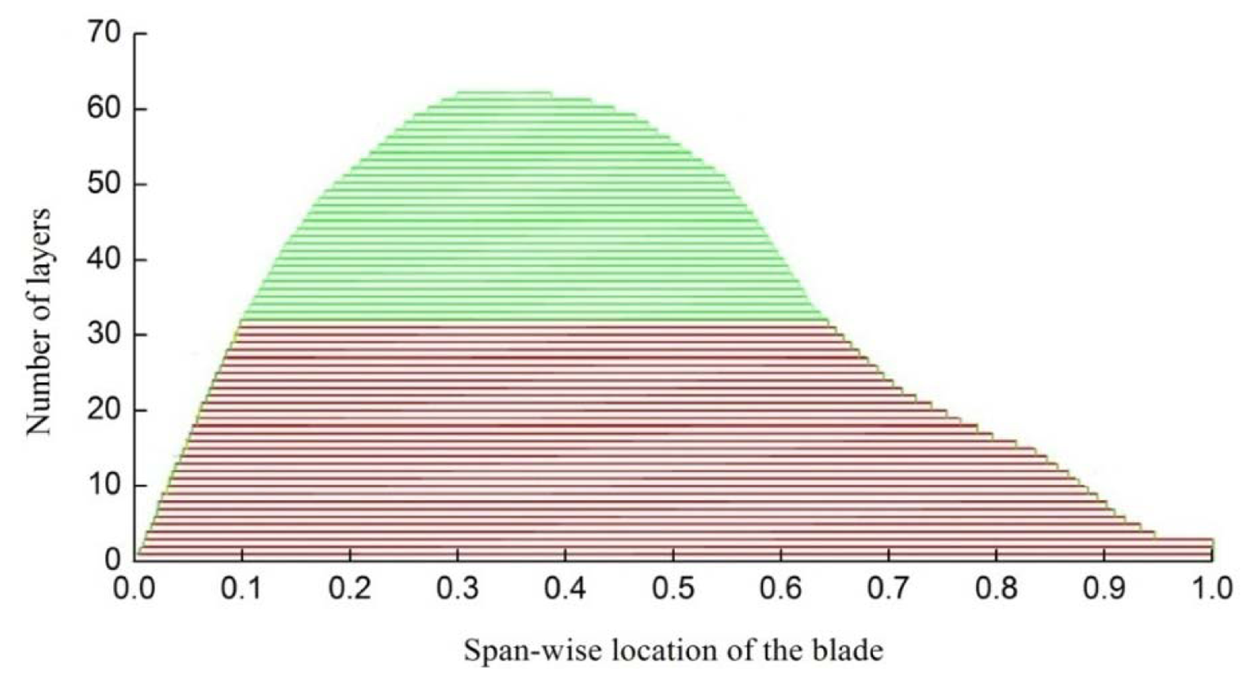
Figure 4 shows the original material layup of the spar cap. The region from 0.1 to 0.66 (shown in green) along the span-wise location of the blade will be optimized because it has a much greater number of layers than the other regions.
Eight discrete control points are used to define the layup of the selected region, and the number of layers changes linearly between the control points, as shown in Figure 5. Point 3 to point 6 each have three parameters that are the location of layers, the number of GFRP and CFRP layers, while the other points each have two parameter that is the number of GFRP and CFRP layers. In addition, point 4 and point 5 have the same number of layers. Two more parameters L1, L2 are used to define the positions of the shear webs and the width of the spar cap, as shown in Figure 1.
Twenty variables in total are defined in this paper, which can be expressed in the following form:
3.2. Design Objectives
The purpose of the present work is to improve the structural characteristics of the blade, reducing both its overall weight and its cost. Therefore, a weight function and a function that combines the main materials cost of the blade represent the objective functions of the problem. The first objective function fw is computed by normalizing the current weight w to the value of the original blade w0, in formula:
The second objective function fc is the ratio between the cost c of the current blade and the cost c0 of the original blade, in formula:
3.3. Constraint Conditions
The structural design of the blade is a multi-criteria constrained optimization problem [4,8]. The strength, stiffness, dynamic behavior, stability and durability design requirements, such as blade/tower clearance limit, strain limit along the fiber direction, surface stress limit, avoiding resonance, buckling resistance and fatigue lifetime over 20 years should be well satisfied [10]. In this paper, the following constraint conditions are taken into account: the strain constraint, the tip deflection, the vibration constraint, the buckling constraint and the fatigue lifetime constraint. These constraints represent the strength, stiffness, dynamic behavior, stability and durability design requirements, respectively:
- (1)
The strain constraint: the strain generated by the loads cannot exceed associated permissible strain [16]. As the permissible strain of GFRP is smaller than that of CFRP, the strain constraints of the parts use only GFRP and the parts use both GFRP and CFRP are defined different. This is expressed as follows:
where εmax is the maximum strain of the parts use both GFRP and CFRP, while is the maximum strain of the parts use only GFRP, εCFRP and εGFRP are the permissible strains of CFRP and GFRP, γS1 is the strain safety factor, C4a and C4b are factors decided by the manufacturing process and the material properties, respectively. For a prepreg process or a semi-automatic manufacturing process, C4a = 1.1. For unidirectional fiber-reinforced composite materials, C4b = 1.1.- (2)
The tip deflection constraint: in order to avoid the risk of blade/tower collisions, the maximum tip deflection should be less than the set value. The Germanischer Lloyd (GL) regulations specify that the quasi-static tip deflection under the extreme unfactored operational loading is not to exceed 50 percent of the clearance without blade deflection. The International Electrotechnical Commission (IEC) 61400-1 specifications, on the other hand, require no blade/tower contact when the extreme loads are multiplied by the combined partial safety factors for loads and the blade material [1]. This can be expressed as follows:
where dmax is the maximum tip deflection; da is the allowable tip deflection; γS2 is the tip deflection safety factor.- (3)
The vibration constraint: a good design philosophy for reducing vibration is to separate the natural frequencies of the blade from the harmonic vibration associated with rotor rotation, which would avoid resonance where large amplitudes of vibration could severely damage the blade. This is expressed in the inequality form:
where Fblade is the first natural frequency of the blade, Frotor is the frequency of the rotor rotation and Δ is the associated allowable tolerance.- (4)
The buckling constraint: since the blade is a thin-walled structure, and it is subjected to large flap-wise bending moments, the surface panels near the blade root are particularly vulnerable to elastic instability, so the buckling problem must be addressed [17]. Generally, ultimate loads are deemed the most likely cause of blade buckling. In order to avoid buckling failure, the buckling load should be greater than ultimate loads. This can be expressed as follows:
where λ1 is a ratio of the buckling load to the maximum ultimate load, called lowest buckling load factor; γS3 is the buckling safety factor. λ1 is calculated using a nonlinear buckling analysis in ANSYS under the above ultimate load conditions.- (5)
The lifetime fatigue constraint: the durability requirement for the turbine blades is typically defined as a minimum 20-year fatigue life (which corresponds roughly to 108 cycles) when subjected to stochastic wind-loading conditions and cyclic gravity-induced edge-wise bending loads in the presence of thermally fluctuating and environmentally challenging conditions [18,19]. In most cases, the lifetime of the blade is controlled by its fatigue strength, which can be defined as follows [7]:
where N is the numb per of cycles corresponding to peak working stress; σmax is the maximum stress of the blade; σY is the allowable material stress; β is a fatigue coefficient that varies for different materials. For the blade composite materials, the value of β is 0.10632 [20]. γS4 is the lifetime safety factor; N0 is the number of allowable cycles.
In addition, considering the manufacturing maneuverability and the continuity of the material layup, the design variables should be satisfied with the following inequality form:
The lower and upper bounds of the variables and the constraint conditions are shown in Table 2.
4. NSGA II
The NSGA II [21–23], which is an improved version of NSGA, is used in this paper. It is one of the most efficient and famous multi-objective evolutionary algorithms and has been widely applied to solve complicated optimization problems.
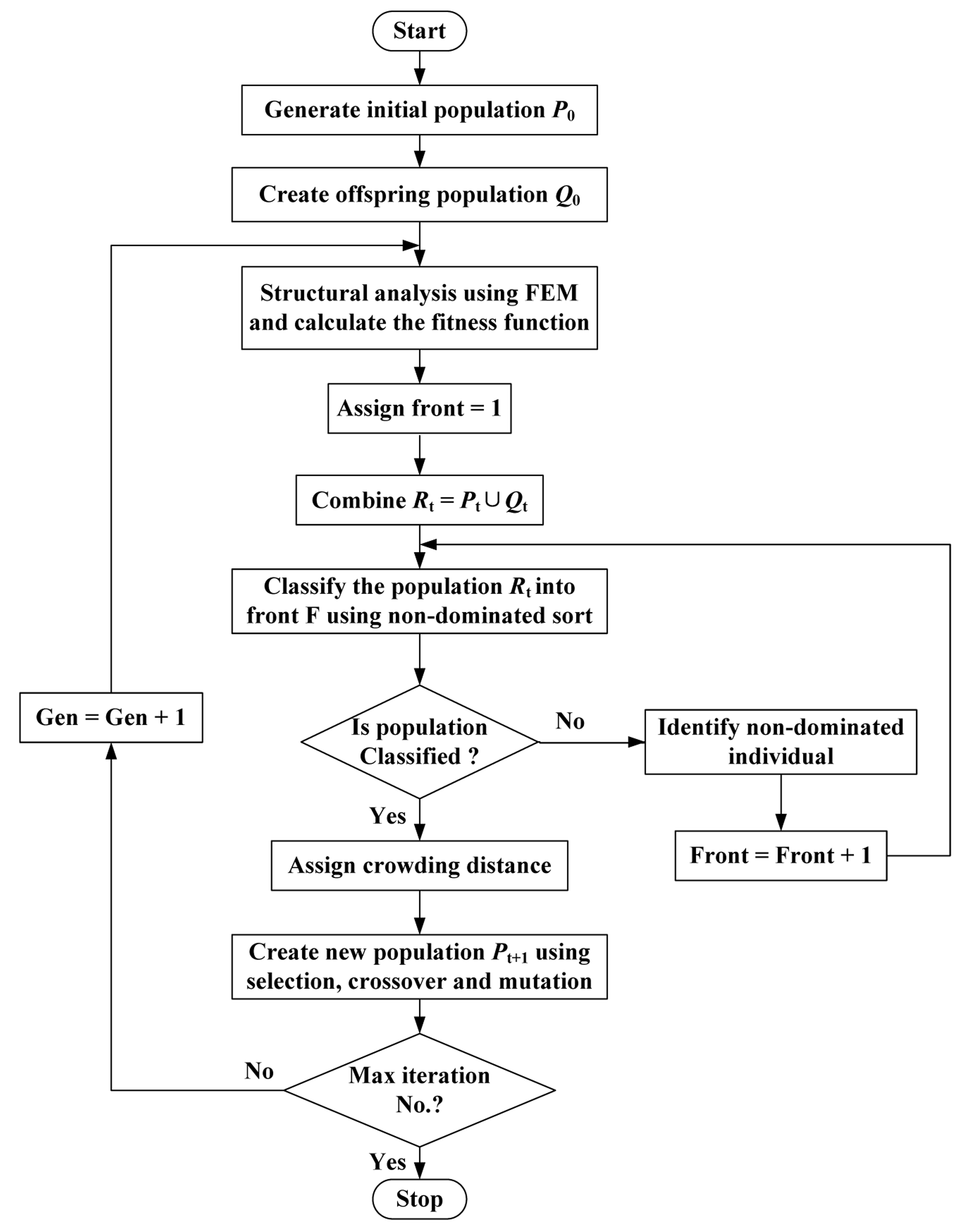
The method randomly generates an initial parent population P0 of size N. The population is sorted based on non-domination and each solution is assigned a fitness equal to its non-domination level (1 is the best level, 2 is the next best level, and so on). An offspring population Q0 with the same size as the parent population is created through recombination based on binary tournament selection and by inducing variations using mutation operators. From the first generation onward, the procedure is different. First, a combined population Rt = Pt ∪ Qt of size 2N is formed, which is sorted according to a fast non-domination procedure. The new parent population Pt+1 is formed by adding solutions from the first front till the size becomes N. Thereafter, the solutions of the last accepted front are sorted according to a crowded comparison operator and the first N points are picked. The new offspring population Qt+1 of size N is regenerated and the procedure is repeated in the subsequent generation. Detail description of the non-dominated sorting approach and the crowded comparison operator can be found in [21]. The flow chart for the algorithm is presented in Figure 6.
The NSGA II parameters used in this paper are listed in Table 3.
5. Results and Analysis
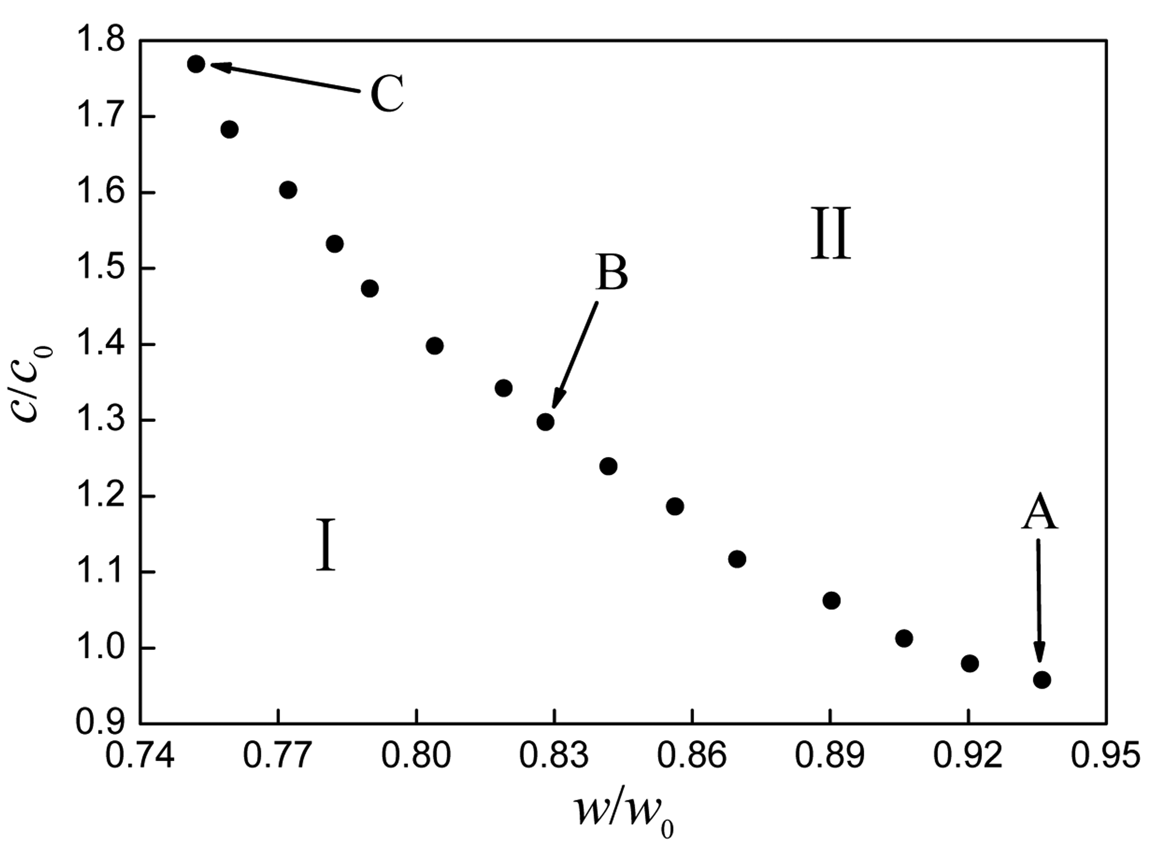
Figure 7 shows the Pareto front obtained by taking the minimum weight and the minimum cost of the blade as the optimization objectives. The curve of the Pareto front illustrates a monotone decreasing trend and divides the optimal region into two parts, i.e., parts I and II. Part I is an ideal solution region that cannot be reached under the design conditions, while part II is a feasible solution region. The Pareto front solutions are the best trade-offs that can be reached in practice. The points on the right hand of the front identify design solutions having low weight yet high cost, whereas the points on the left hand of the front present design solutions having low cost but high weight. It cannot be said which point on the Pareto front is much better than others in theory. The choice of the solution in the practical design should be made according to the designer's preference for less weight or less cost.
To better explain the formation of the Pareto front, three optimized solutions extracted at different positions on the Pareto front are analyzed, as marked in Figure 7. The values of the design variables of blades A, B, C and the original design are listed in Table 4. Because CFRP is much lighter and stronger than GFRP, but more expensive, thus the costs of the three blades increase with the number of CFRP layers, while the total number of layers and the blade weights decrease.
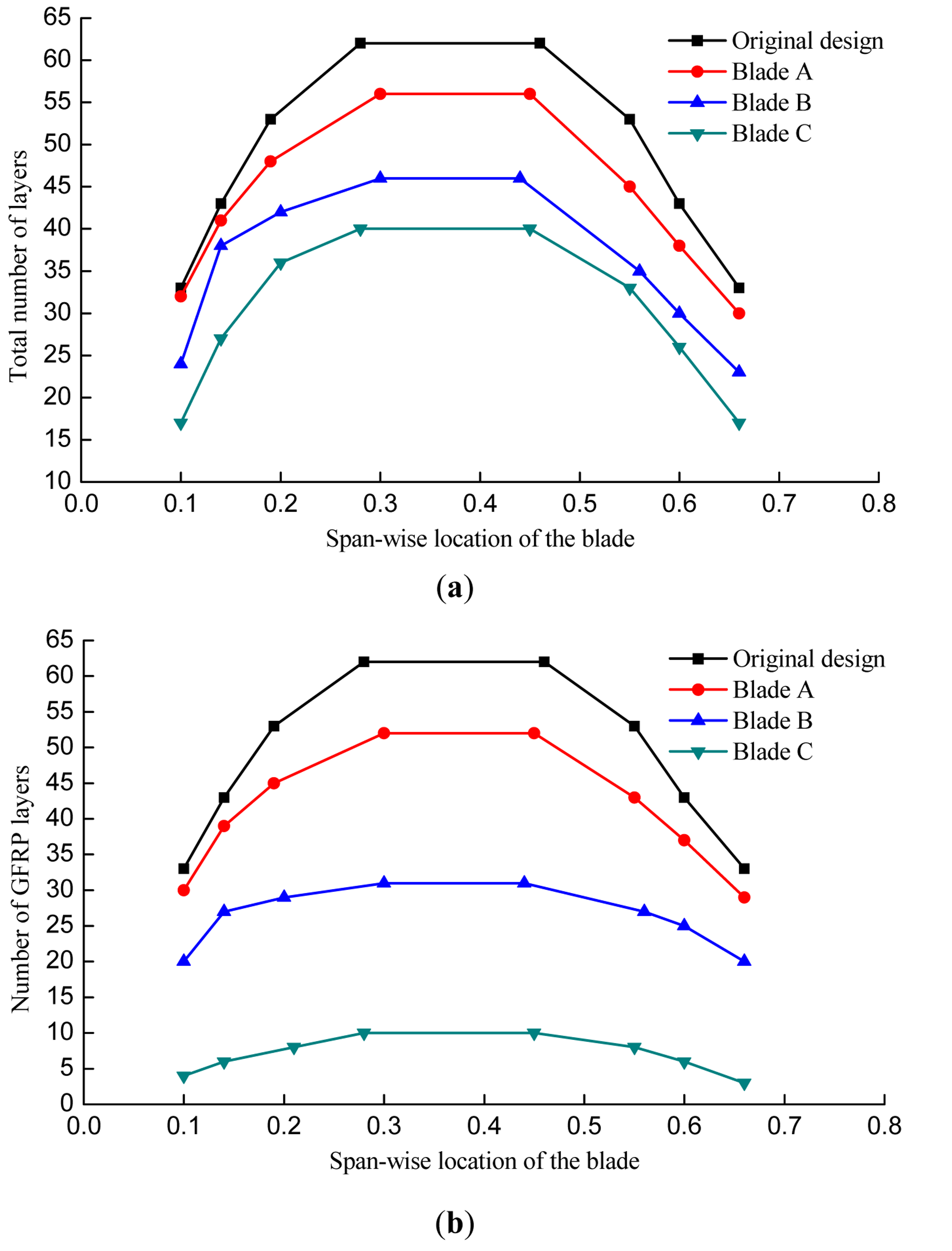
Figure 8 shows the total material layup and GFRP layup of the spar cap. It can be seen that the total number of layers and the number of GFRP layers both decrease obviously, especially from 0.19 to 0.56 along the span-wise locations of the blade after optimization, and the thickest region becomes smaller. It indicates that the two regions from 0.1 to 0.19 and 0.56 to 0.66 have a less impact on the objectives than the middle part. As the region from 0.1 to 0.19 withstands a larger bending moment, the number of layers in this region is a bit more than it in the region from 0.56 to 0.66 after optimization.
The position of the shear webs and the width of the spar cap both decrease after optimization. In order to find the effect of the position of the shear webs on the structural performance of the blade, a sensitivity analysis has been carried out. The result shows that the moving the shear webs to the centerline of the spar cap can reduce the maximum equivalent strain, i.e., improve the strength of the blade. A smaller width of the spar cap can reduce the amount of materials, which is beneficial for reducing the cost as well as the weight of the blade.
The structural performance of the blade is presented in Table 5. Compared with the original blade, the weights of the blades A, B, C decrease by 6.4%, 16.9% and 24.8%, respectively, while the values of cost change by 4.2%, −29.4% and −76.8%, respectively. The decrease of the maximum tip deflections, the increase of the first natural frequencies and the lowest buckling load factors from blade A to blade C are a result of increasing the number of CFRP layers, which is good for improving the blade stiffness and reducing the response of the blade being excited.
The decrease in total number of layers leads to a degradation in the fatigue strength of the blade, thus the fatigue lifetime gradually approaches the critical value after optimization. Since the blade A has both lower cost and less weight than the original blade, it seems to be a more desirable result than the other blades by the consideration of the present two optimization objectives.
6. Conclusions
This paper illustrates a two-objective optimization method that uses NSGA II and a FEM model for the structural design of HAWT blades. The method is used to obtain the best trade-off solutions between the blade weight and the cost. The NSGA II handles the design parameters chosen for optimization and searches for the group of optimal solutions following the basic principles of Genetic Programming and Pareto concepts. The FEM model utilizes ANSYS to determine the structural performance of a HAWT blade, while it measures the fitness functions of the optimization as well.
The method has been applied successfully to a 1.5 MW commercial HAWT blade, and a set of trade-off solutions are obtained. The results indicate that the minimization of mass requires more CFRP, while the minimization of cost requires a good arrangement of GFRP combined with CFRP. Satisfactory results to reduce the weight as well as the cost of the blade are achieved and significant improvements in the structural performance of the blade are obtained by rearranging the original material layup in the spar cap, the width of the spar cap and the positions of the shear webs, which can be advantageous from the production and manufacturing requirements point of views.
Acknowledgments
This work was supported by the Jiangsu Collaborative Innovation Center for Coastal Development and Protection (Jiangsu Government Office Document [2013] No. 56) and the Science and Technology Plan to Guide the Project of Nantong (2013400303).
Conflicts of Interest
The authors declare no conflict of interest.
References
- Burton, T. Wind Energy Handbook; John Wiley & Sons Ltd: Chichester, UK, 2001. [Google Scholar]
- Locke, J; Valencia, U. Design Studies for Twist-Coupled Wind Turbine Blades; U.S. Department of Energy: Washington, DC, USA, 2004. [Google Scholar]
- Veers, P.S.; Ashwill, T.D.; Sutherland, H.J.; Laird, D.L.; Lobitz, D.W. Trends in the design, manufacture and evaluation of wind turbine blades. Wind Energy 2003, 6, 245–259. [Google Scholar]
- Liao, C.C.; Zhao, X.L.; Xu, J.Z. Blade layers optimization of wind turbines using FAST and improved PSO. Renew. Energy 2012, 42, 227–233. [Google Scholar]
- Zhu, J.; Cai, X.; Pan, P.; Gu, R.R. Optimization design of spar cap layup for wind turbine blade. Front. Struct. Civ. Eng. 2012, 6, 53–56. [Google Scholar]
- Cai, X.; Zhu, J.; Pan, P.; Gu, R.R. Structural optimization design of horizontal-axis wind turbine blades using a particle swarm optimization algorithm and finite element method. Energies 2012, 5, 4683–4696. [Google Scholar]
- Hu, W.F.; Han, I.; Park, S.C.; Choi, D.H. Multi-objective structural optimization of a HAWT composite blade based on ultimate limit state analysis. J. Mech. Sci. Technol. 2012, 26, 129–135. [Google Scholar]
- Jureczko, M.; Pawlak, M.; Mezyk, A. Optimisation of wind turbine blades. J. Mater. Proc. Technol. 2005, 167, 463–471. [Google Scholar]
- Jensen, F.M.; Falzon, B.G.; Ankersen, J.; Stang, H. Structural testing and numerical simulation of a 34 m composite wind turbine blade. Compos. Struct. 2006, 76, 52–61. [Google Scholar]
- Kong, C.; Bang, J.; Sugiyama, Y. Structural investigation of composite wind turbine blade considering various load cases and fatigue life. Energy 2005, 30, 2101–2114. [Google Scholar]
- Lund, E.; Stegmann, J. On structural optimization of composite shell structures using a discrete constitutive parametrization. Wind Energy 2005, 8, 109–124. [Google Scholar]
- Maheri, A.; Noroozi, S.; Vinney, J. Combined analytical/FEA-based coupled aero structure simulation of a wind turbine with bend–twist adaptive blades. Renew. Energy 2007, 32, 916–930. [Google Scholar]
- Buckney, N.; Green, S.; Pirrera, A.; Weaver, P.M. On the structural topology of wind turbine blades. Wind Energy 2013, 16, 545–560. [Google Scholar]
- Buckney, N.; Pirrera, A.; Green, S.D.; Weaver, P.M. Structural efficiency of a wind turbine blade. Thin Wall Struct 2013, 67, 144–154. [Google Scholar]
- Lee, Y.J.; Jhan, Y.T.; Chung, C.H. Fluid-structure interaction of FRP wind turbine blades under aerodynamic effect. Compos. Part B 2012, 43, 2180–2191. [Google Scholar]
- Rotor Blades of Wind Turbine; JB/T10194-2000; China Standards: Beijing, China, 2000; in Chinese.
- Lund, E. Buckling topology optimization of laminated multi-material composite shell structures. Compos. Struct. 2009, 91, 158–167. [Google Scholar]
- Grujicic, M.; Arakere, G.; Subramanian, E.; Sellappan, V.; Vallejo, A.; Ozen, M. Structural-response analysis, fatigue-life prediction, and material selection for 1 MW horizontal-axis wind-turbine blades. J. Mater. Eng. Perform. 2010, 19, 790–801. [Google Scholar]
- Grujicic, M.; Arakere, G.; Pandurangan, B.; Sellappan, V.; Vallejo, A.; Ozen, M. Multidisciplinary design optimization for glass-fiber epoxy-matrix composite 5 MW horizontal-axis wind-turbine blades. J. Mater. Eng. Perform. 2010, 19, 1116–1127. [Google Scholar]
- Mandall, J.F.; Samborsky, D.D.; Cairns, D.S. Fatigue of Composite Materials and Substructures for Wind Turbine Blades; Sandia Report No. SAN2002-0771; Sandia National Laboratories: Albuquerque, NM, USA, 2002. [Google Scholar]
- Deb, K.; Pratap, A.; Agarwal, S.; Meyarivan, T. A fast and elitist multiobjective genetic algorithm: NSGA-II. IEEE Trans. Evol. Comput. 2002, 6, 182–197. [Google Scholar]
- Palanikumar, K.; Latha, B.; Senthilkumar, V.S.; Karthikeyan, R. Multiple performance optimization in machining of GFRP composites by a PCD tool using non-dominated sorting genetic algorithm (NSGA-II). Met. Mater. Int. 2009, 15, 249–258. [Google Scholar]
- Serrano, V.; Alvarado, M.; Coello, C.A.C. Optimization to Manage Supply Chain Disruptions Using the NSGA-II. In Theoretical Advances and Applications of Fuzzy Logic and Soft Computing; Springer: Berlin/Heidelberg, Germany, 2007; pp. 476–485. [Google Scholar]

| Material | E1 (GPa) | E2 (GPa) | G12 (GPa) | v12 | ρ (kg/m3) | Cost (m3) |
|---|---|---|---|---|---|---|
| GFRP | 42.19 | 12.53 | 3.52 | 0.24 | 1910 | 1 |
| CFRP | 130.00 | 10.30 | 7.17 | 0.28 | 1540 | 10 |
| Parameter | Lower bound | Upper bound | Units |
|---|---|---|---|
| x1 | 0 | 38 | - |
| x2 | 0 | 48 | - |
| x3 | 0 | 58 | - |
| x4 | 0 | 65 | - |
| x5 | 0 | 55 | - |
| x6 | 0 | 45 | - |
| x7 | 0 | 40 | - |
| x8 | 0 | 30 | - |
| x9 | 0 | 35 | - |
| x10 | 0 | 40 | - |
| x11 | 0 | 45 | - |
| x12 | 0 | 40 | - |
| x13 | 0 | 35 | - |
| x14 | 0 | 30 | - |
| x15 | 0.17 | 0.23 | - |
| x16 | 0.25 | 0.33 | - |
| x17 | 0.41 | 0.49 | - |
| x18 | 0.53 | 0.59 | - |
| x19 | 0.13 | 0.25 | m |
| x20 | 0.50 | 0.70 | m |
| εmax | - | 5,000 | μ |
| E'max | - | 3,180 | μ |
| dmax | - | 5.5 | m |
| Fblade | ≤0.94 or ≥0.96 | Hz | |
| λ1 | 1.30 | - | - |
| N | 1.20 × 10⁸ | - | - |
| Parameters | Value |
|---|---|
| Number of individuals | 20 |
| Number of iterations | 50 |
| Probability of crossover | 0.8 |
| Probability of mutation | 0.01 |
| Peremeter | Original design | Blade A | Blade B | Blade C | Unit |
|---|---|---|---|---|---|
| x1 | 33 | 30 | 20 | 5 | - |
| x2 | 43 | 39 | 27 | 6 | - |
| x3 | 53 | 45 | 29 | 9 | - |
| x4 | 62 | 53 | 31 | 10 | - |
| x5 | 53 | 43 | 27 | 8 | - |
| x6 | 43 | 37 | 25 | 6 | - |
| x7 | 33 | 29 | 20 | 3 | - |
| x8 | 0 | 2 | 4 | 12 | - |
| x9 | 0 | 2 | 11 | 21 | - |
| x10 | 0 | 3 | 13 | 27 | - |
| x11 | 0 | 3 | 15 | 30 | - |
| x12 | 0 | 2 | 8 | 25 | - |
| x13 | 0 | 1 | 5 | 20 | - |
| x14 | 0 | 1 | 3 | 14 | - |
| x15 | 0.19 | 0.19 | 0.20 | 0.20 | - |
| x16 | 0.28 | 0.30 | 0.30 | 0.28 | - |
| x17 | 0.46 | 0.45 | 0.44 | 0.45 | - |
| x18 | 0.55 | 0.55 | 0.56 | 0.55 | - |
| x19 | 0.188 | 0.146 | 0.143 | 0.142 | m |
| x20 | 0.62 | 0.58 | 0.55 | 0.54 | m |
| Scheme | Blade weight | Cost | Maximum equivalent strain (μ) | Maximum tip deflection (m) | The first natural frequency (Hz) | The lowest buckling loadfactor | The lifetime cycles | |
|---|---|---|---|---|---|---|---|---|
| GFRP | CFRP | |||||||
| Original design | 1.000 | 1.000 | 4074 | 4286 | 4.59 | 1.027 | 2.02 | 2.28 × 10⁸ |
| Blade A | 0.936 | 0.958 | 4859 | 3143 | 5.13 | 1.016 | 1.45 | 1.73 × 10⁸ |
| Blade B | 0.831 | 1.294 | 4253 | 3056 | 3.77 | 1.210 | 1.87 | 1.61 × 10⁸ |
| Blade C | 0.752 | 1.768 | 4685 | 3131 | 3.01 | 1.328 | 2.33 | 1.32 × 10⁸ |
© 2014 by the authors; licensee MDPI, Basel, Switzerland. This article is an open access article distributed under the terms and conditions of the Creative Commons Attribution license ( http://creativecommons.org/licenses/by/3.0/).
Share and Cite
Zhu, J.; Cai, X.; Pan, P.; Gu, R. Multi-Objective Structural Optimization Design of Horizontal-Axis Wind Turbine Blades Using the Non-Dominated Sorting Genetic Algorithm II and Finite Element Method. Energies 2014, 7, 988-1002. https://doi.org/10.3390/en7020988
Zhu J, Cai X, Pan P, Gu R. Multi-Objective Structural Optimization Design of Horizontal-Axis Wind Turbine Blades Using the Non-Dominated Sorting Genetic Algorithm II and Finite Element Method. Energies. 2014; 7(2):988-1002. https://doi.org/10.3390/en7020988
Chicago/Turabian StyleZhu, Jie, Xin Cai, Pan Pan, and Rongrong Gu. 2014. "Multi-Objective Structural Optimization Design of Horizontal-Axis Wind Turbine Blades Using the Non-Dominated Sorting Genetic Algorithm II and Finite Element Method" Energies 7, no. 2: 988-1002. https://doi.org/10.3390/en7020988
APA StyleZhu, J., Cai, X., Pan, P., & Gu, R. (2014). Multi-Objective Structural Optimization Design of Horizontal-Axis Wind Turbine Blades Using the Non-Dominated Sorting Genetic Algorithm II and Finite Element Method. Energies, 7(2), 988-1002. https://doi.org/10.3390/en7020988


